Few days ago I tested AD9850 DDS module in home in hope to some day have a working signal generator using it. The initial tests went well, so I could plan the next step. I was already doing some information searching to make decision if I should do the controlling using web interface (with Ethernet shield) or should I rather stick to traditional serial console controlling (through virtual serial port over USB).
When I tried to make decision on that and thinking of how much time is needed to implement the basic application for this use, I found interesting skech, something pretty much in line I was planning to code myself. When there is ready made free code, then why not use it… I found the code at https://gist.github.com/raivisr/3861473. It starts with the following documentation:
/*
Simple controller for AD9850 modules
Uses serial protocol (refer to AD9850 datasheet what pins need to be pulled up/down
Uses library by Elecfreaks http://elecfreaks.com/store/download/datasheet/breakout/DDS/EF_AD9850_library.zip
(for use with chipkit delete that unnecessary line “#include <avr/pgmspace.h>” from .h file)
Fix the pin numbers used to communicate with module
Serial comms – 9600, NewLine (0x0A) denotes end of input,
f 10000 – set frequency
s 20 20000 10 1000 – sweep from frequency to frequency using this step size in that many milliseconds
o 10 10000 5 3000 – oscillating sweep from frequency to frequency and back using this step size in that many ms
NB! no error checking in input, code relies on intelligence of user
*/
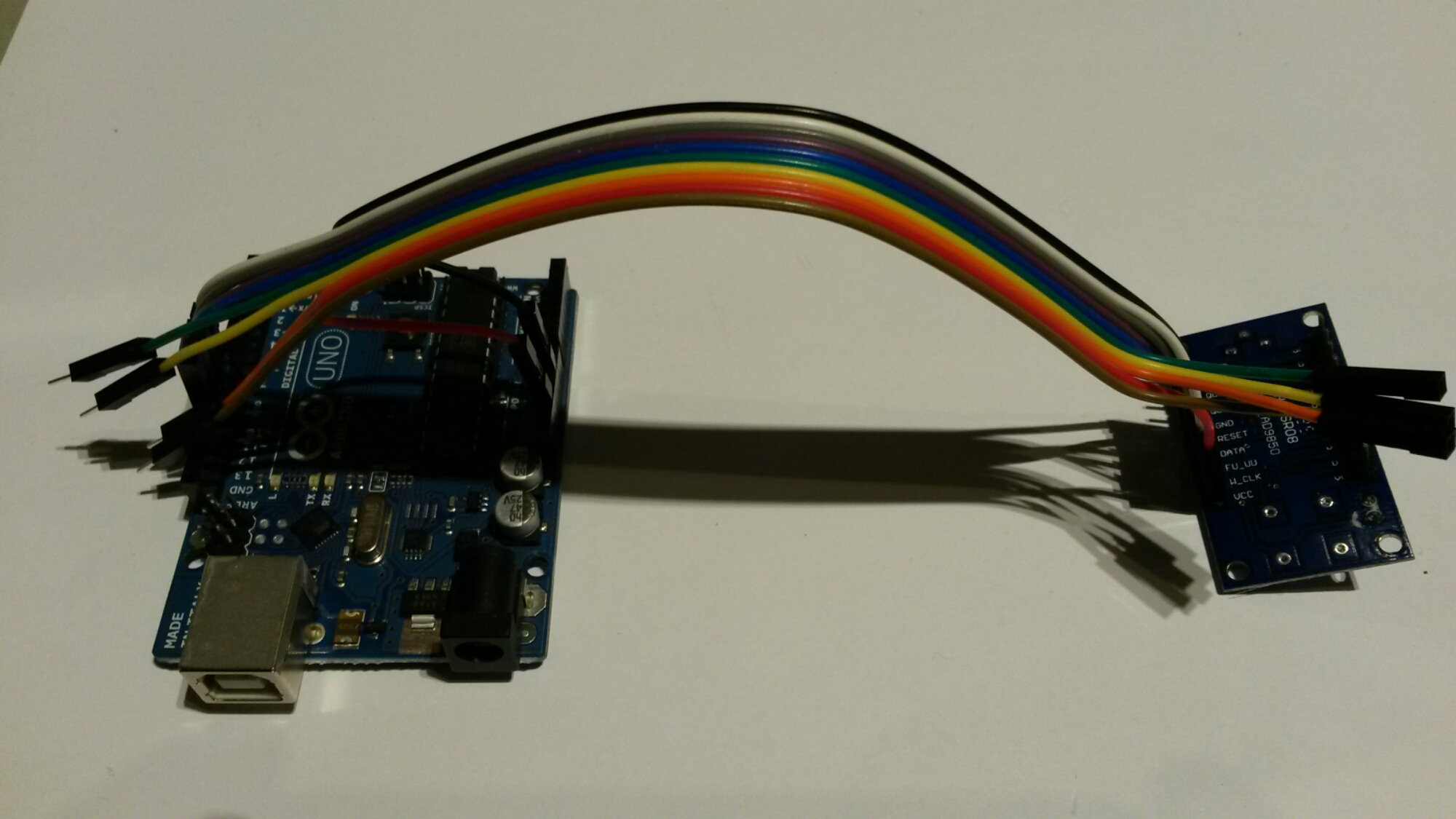
It looked pretty what I was looking for. So I did Cut&pase from web page and changed module connection configuration to match my wiring:
EF_AD9850 AD9850(8, 9, 11, 10);
Next task was to compile the thing and load to Arduino. But in this step I got compiling problems: Error messages told that EF_AD8950.h was missing..
Because the source code did not seem to have pointer to the needed library, I had to use Google searches in hope to find that. I found what I was looking at http://rockingdlabs.dunmire.org/exercises-experiments/ad-9850-dds-synthesizer. So I downloaded the needed library from link http://elecfreaks.com/store/download/datasheet/breakout/DDS/EF_AD9850_library.zip
Then I copied the library file form ZIP to to C:\Users\Tomi\Documents\Arduino\libraries\EF_AD9850
Tried compiling: Still problems with #include "WProgram.h"
I solved those problems with instructions from http://makezine.com/2011/12/01/arduino-1-0-is-out-heres-what-you-need-to-know/. So I needed to replace
#include "WProgram.h"
line at C:\Users\Tomi\Documents\Arduino\libraries\EF_AD9850\EF_AD8950.h with following (using Notepad++ editor):
#if ARDUINO >= 100
  #include "Arduino.h"
#else
  #include "WProgram.h"
#endif
Now I got the code to compile correctly.
I loaded the code to the Arduino Uno and started communication test with is using Serial Monitor provided with Arduino IDE. I connected my oscilloscope/multimeter between ZOUT1 and GND pins to monitor the output signal.
First test: f 10000 – set frequency
Sent: f 10000
Result: Nothing. After some investication I found out that I had to have the setting “No line ending” in Serial Monitor. I changed that option to “Both NL & CR” and got everythign working well. I tried different frequencies from 1 Hz to 20 MHz, and they worked well.
Next test: s 20 20000 10 1000 – sweep from frequency to frequency using this step size in that many milliseconds
Third test: o 10 10000 5 3000 – oscillating sweep from frequency to frequency and back using this step size in that many ms
One question raised after testing: How to turn off? Just set frequency to zero, meaning “f 0″ or just “f”.
The two analogue signal outputs give out around 0.5V signal level sinewave at about 100 ohms impedance. Both outputs give out same frequency but the outputs have 90 degrees phase shift between them. In addition to that there are TTL level square wave outs.
5 Comments
Tomi Engdahl says:
Article on some more testing with this signal generator:
AD9850 scalar network analyzer
http://www.epanorama.net/newepa/2015/03/24/ad9850-scalar-network-analyzer/
Tomi Engdahl says:
Another clock generator project based on Arduino and Si5351 clock generator:
Triple Frequency VFO on a Bamboo Breadboard
http://hackaday.com/2015/10/13/triple-frequency-vfo-on-a-bamboo-breadboard/
Historically when hams built low power (QRP) transmitters, they’d use a crystal to set the frequency. Years ago, it was common to find crystals in all sorts of radios, including scanners and handheld transceivers. Crystals are very stable and precise and it is relatively easy to make a high quality oscillator with a crystal and a few parts.
The big problem is you can’t change the frequency much without changing crystals. Making a high quality variable frequency oscillator (VFO) out of traditional components is quite a challenge.
[N2HTT] likes to build radio projects and he decided to take an Si5351 clock generator and turn it into a three frequency VFO for his projects. The Si5351 uses a crystal, so it is very stable. However, you can digitally convert that crystal frequency into multiple frequencies over a range of about 8kHz to 160MHz.
The device [N2HTT] used is in a tiny 10 pin MSOP package, but there are plenty of inexpensive breakout boards available.
One thing of interest is the breadboard the VFO is built on. [N2HTT] used an Arduino and a small display along with an encoder to control the chip. But the chip generates some high frequencies and common wisdom is that solderless breadboards aren’t good for high frequency. Acting on a tip he read in a magazine article [N2HTT] took a bamboo cutting board and then affixed standard solderless breadboards to unetched copper PCB material. He then made sure the PCB ground planes were well connected and grounded. It seems to work
Tomi Engdahl says:
Home> Test-and-measurement Design Center > How To Article
Optimizing Arduino and the AD9851 DDS signal generator
http://www.edn.com/design/test-and-measurement/4441389/Optimizing-Arduino-and-the-AD9851-DDS-signal-generator?_mc=NL_EDN_EDT_EDN_weekly_20160218&cid=NL_EDN_EDT_EDN_weekly_20160218&elqTrackId=93130b0fb1224345af923f5cfdc6794b&elq=67b4966efe9f430b8e0133b911161c89&elqaid=30892&elqat=1&elqCampaignId=27031
Arduino has taken the product “maker” world by storm and one of the more popular Arduino modules is the Analog Devices AD9851 DDS waveform generator. An Internet Web search for “Arduino DDS” showed more than 100,000 results, while the same video search turned up many dozens of videos. Internet forums are filled with discussions related to two specific issues. One issue is that the output amplitude is not constant with frequency, requiring a level control loop. The second issue is that the distortion gets pretty horrific, particularly at higher output frequency settings. In this article, we’ll show how to correct these issues, as well as providing some additional tips for improving the quality of the output.
DDS basics
While this article concentrates on the AD9851 device, Analog Devices produces many others that operate in a similar fashion. The devices combine a clock reference with a digital divider and a phase locked loop to provide a sinewave output with very fine resolution. In the case of the AD9851, the digital divider is 32 bits and the clock frequency is typically 125 MHz. This results in a frequency resolution of approximately 30 milli-Hz. A single resistor, Rset controls the current output level and therefore the output voltage level.
The digital nature of the DDS process results in an output signal and many signal images. The images follow a sin(x)/x envelope.
Tomi Engdahl says:
All Digital FM modulation w/ Arduino & AD9850
https://zissisprojects.wordpress.com/2014/02/10/all-digital-fm-modulation-w-arduino-ad9850/
Here is an attempt to frequency modulate (FM) an RF wave using arduino software and cheap hardware.
The code can be found here. The connection to the AD9850 module is made with SPI hardware interface. It is much more faster than simple serial communication and comparable to parallel communication speed.This DDS module wants a 40 bit word to tune in and synthesize a frequency. If we consider 8bit parallel (e.g. using PORTB) the MCU needs 5(x8bit=40bit) bytes to pass through to send the tuning word to the DDS. Well after doing all the measurements this procedure takes about 4μS to tune the DDS which is extremely fast for our application. But the disadvantage is that the arduino is made to be kept simple with not many wires, and not a huge misreading code etc. so parallel is an option but not to get married with.
Tomi Engdahl says:
Cheap Arduino based DDS Signal Generator using AD9851 module
https://www.youtube.com/watch?v=jTeOIWke-dM
AD9851 based signal generator using Arduino Nano, LCD display and a rotary encoder.
Digital Signal Generator based on the AD9851 module. Using Arduino as the controller.
https://github.com/umarsear/Arduino-AD9851-DDS-Direct-Digital-synthesizer-Signal-Generator