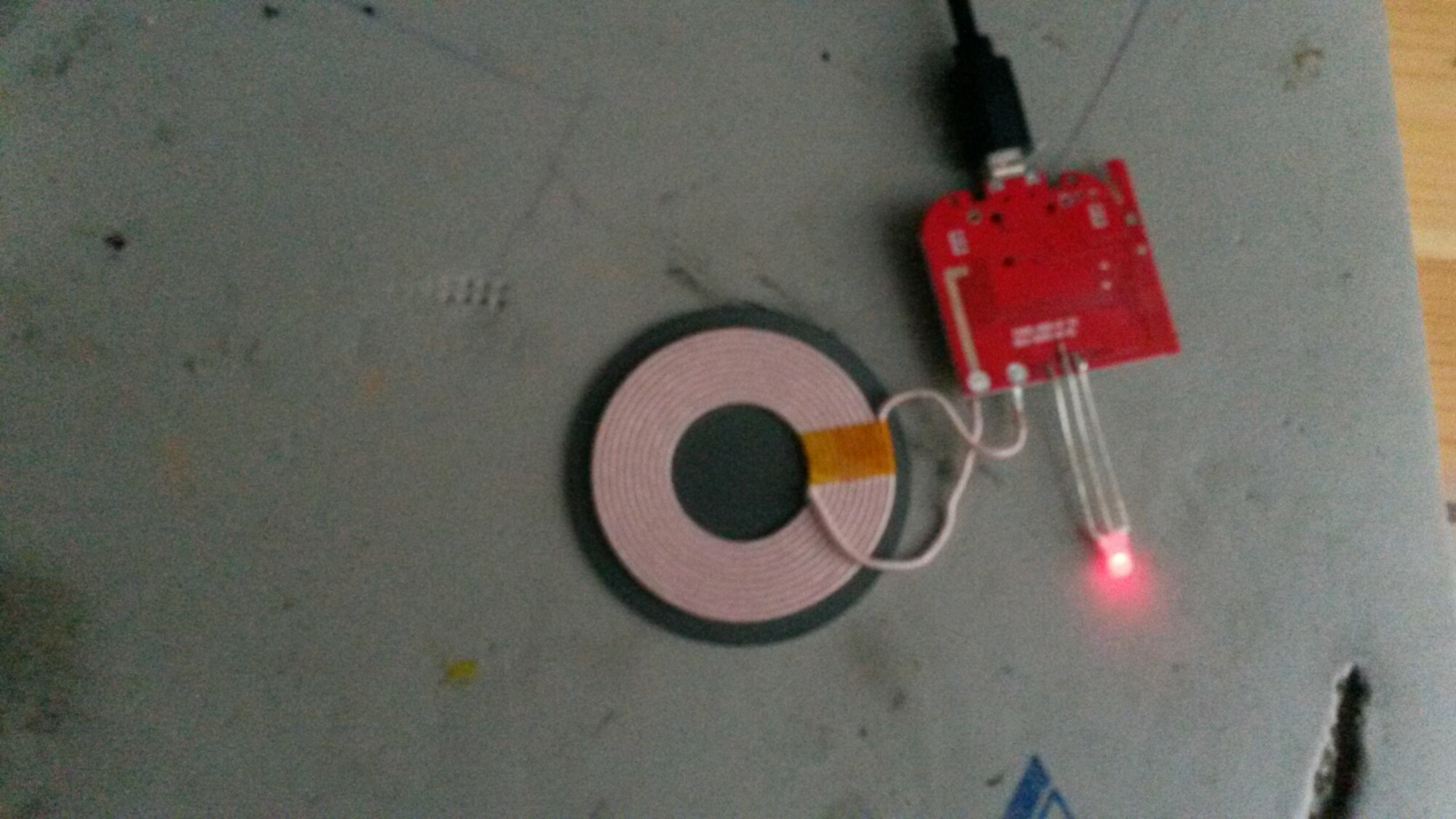
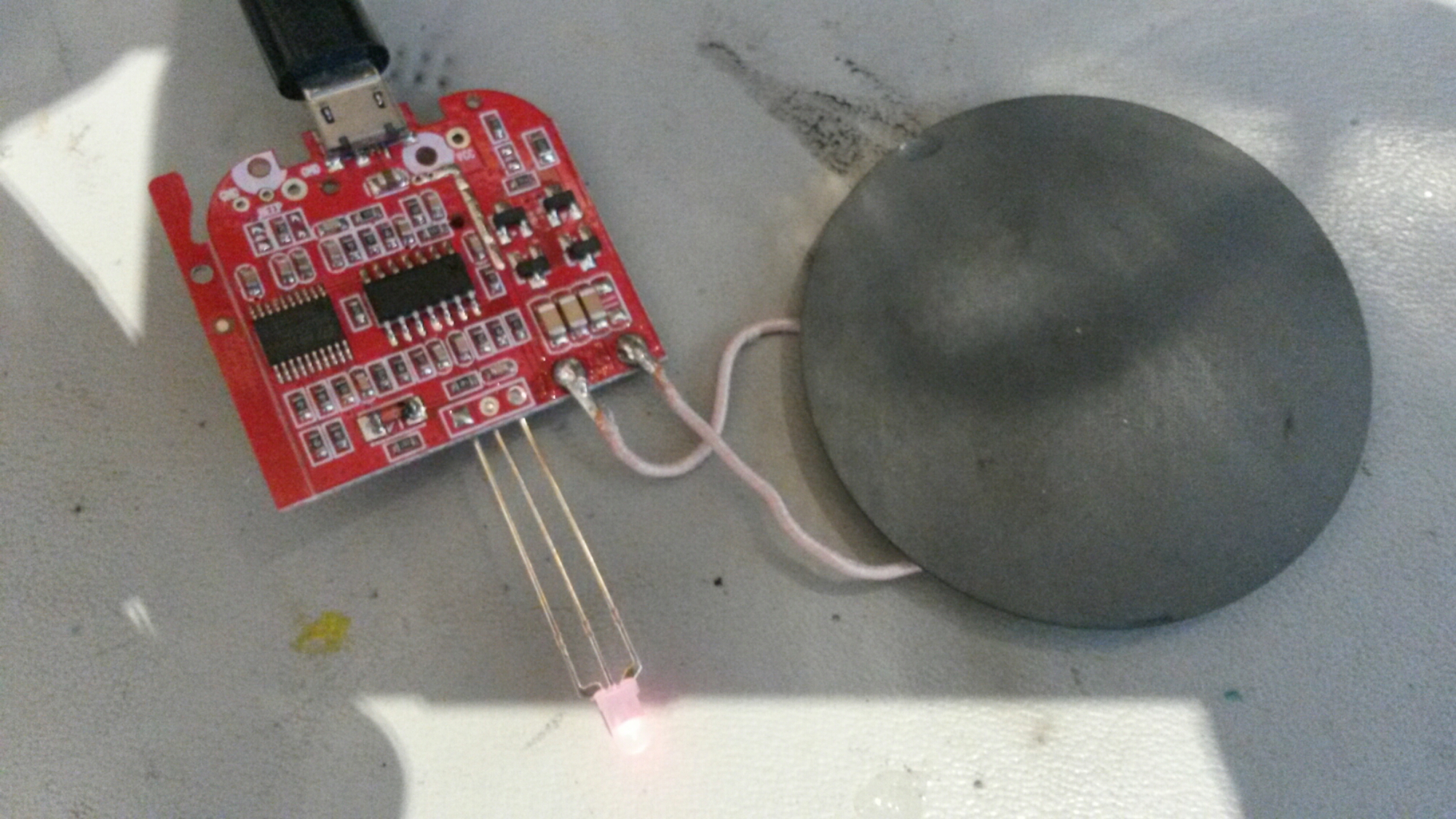
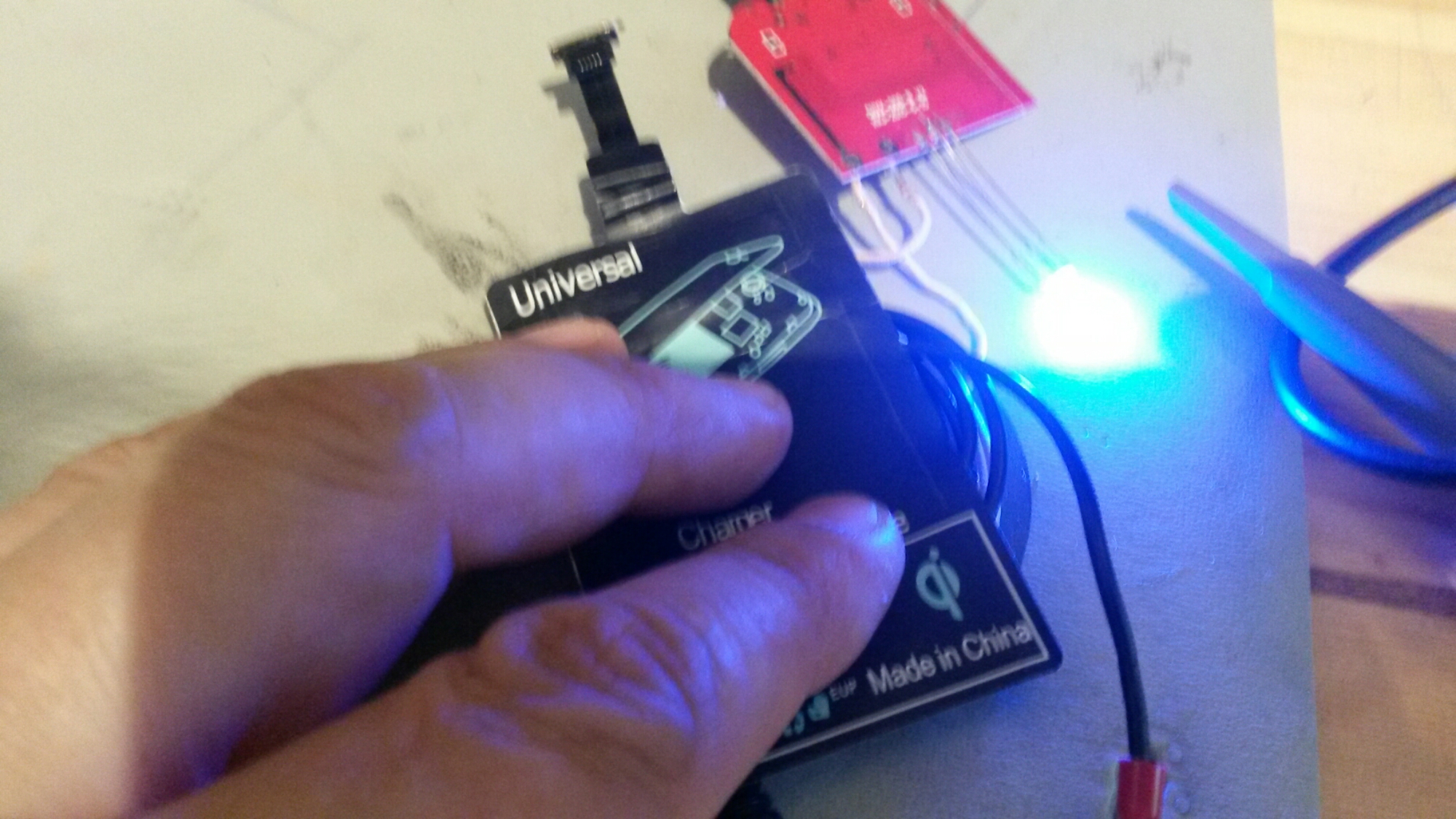
I have written several postings on Qi wireless power. To get a good idea how Qi really works, I bought cheap bare Qi charger board Qi Wireless Charger PCBA Circuit Board + Coil Charging (costs only slightly over two Euros / USD).Qi Wireless Charger PCBA Circuit Board + Coil Charging kit consists ofQi Wireless Charger PCBA Circuit Board + Charging Coil without any case. The charging coil has 10 turns in it and there is a ferrite below the coil.
1.Qi wireless charger PCBA circuit board,allows to charge for any Qi-enabled device.
2.Better for DIY, you can give it a case (not too thick) or fix it on your furniture or other devices, but please note the transfer efficient distance is only 5mm.
3.High power, quick-acting charging.
4.Over 75% high-efficient energy conversion.
5.Ultrathin,lightweight,safe and reliable.
1.Input voltage: DC5V
2.Input current: 2A
3.Charging voltage: 5V
4.Charging current: 500-1000mA
5.Charging power: 10W
6.Charging distance: 5mm
7.Conversion: ≥75%
8.Size: 32 x 31mm
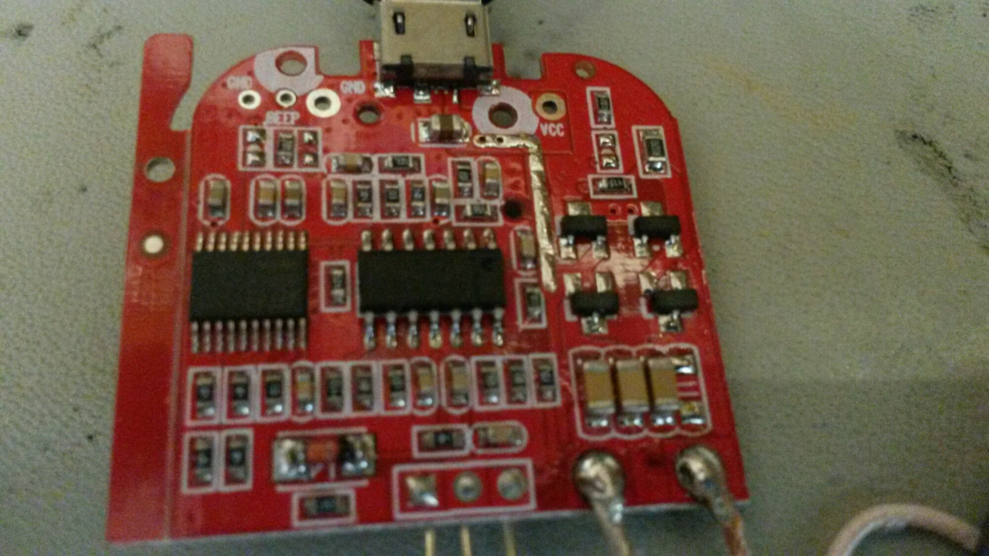
Closeup of the circuit board electronics reveals the main ICs: 8s003f3p6 microcontroller as charge controller, LM324 quad op amp and driver transistors (two C009T and two 3401).
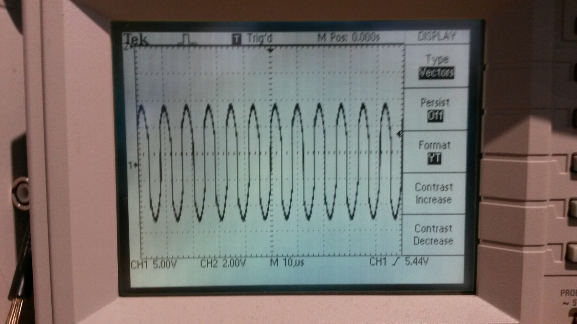
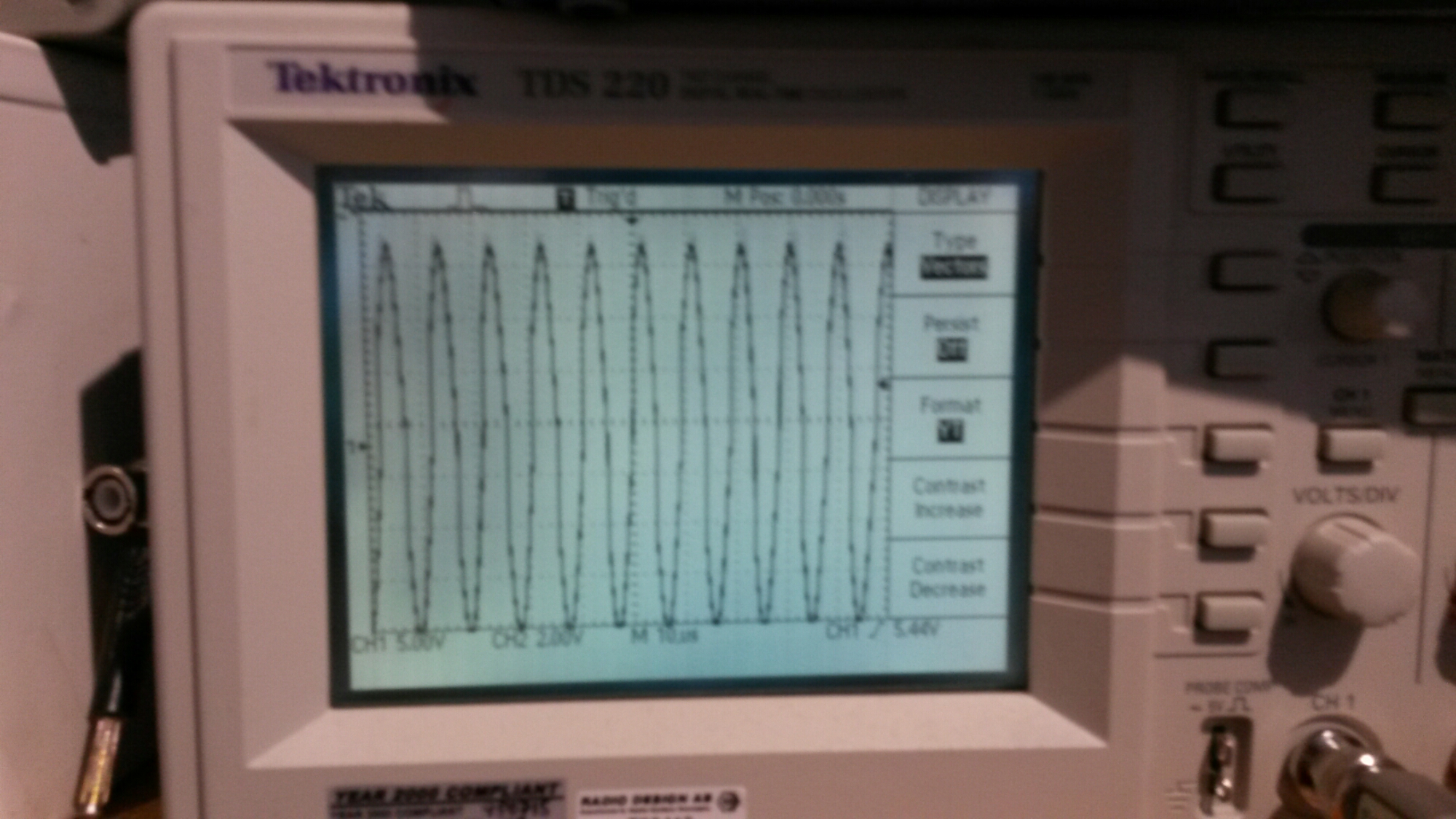
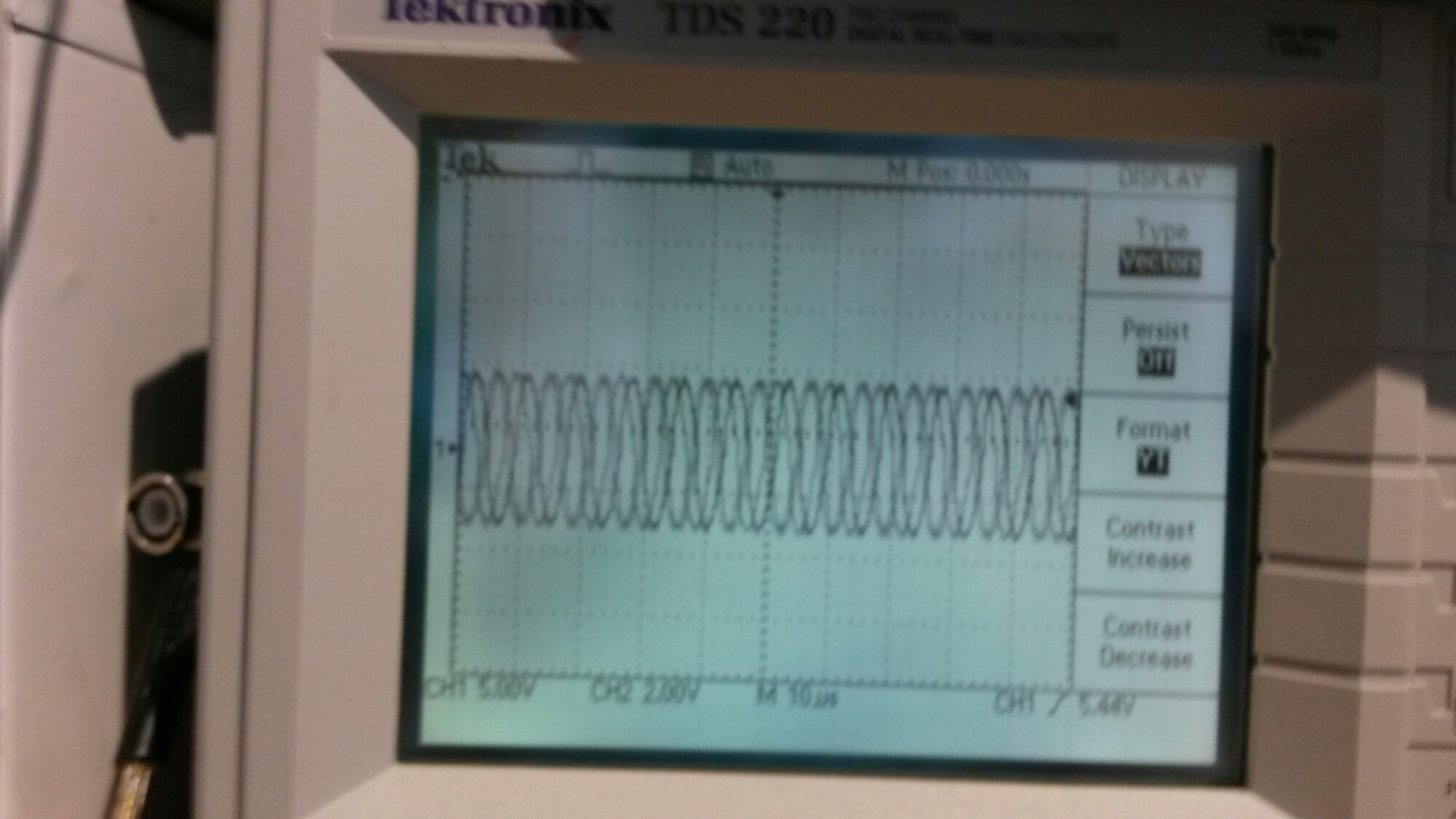
When nothing to charge the charger sends short pulses of low power signals few times a second, measured with scope from charger coil ends with channel CH1.
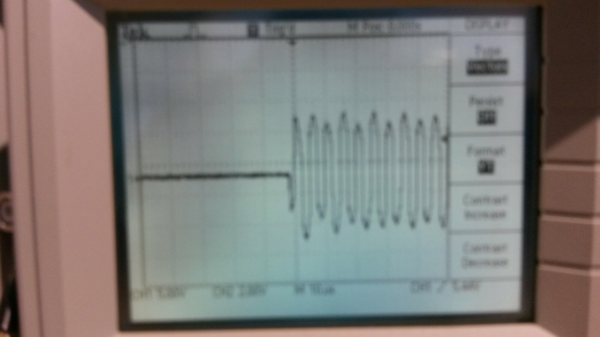
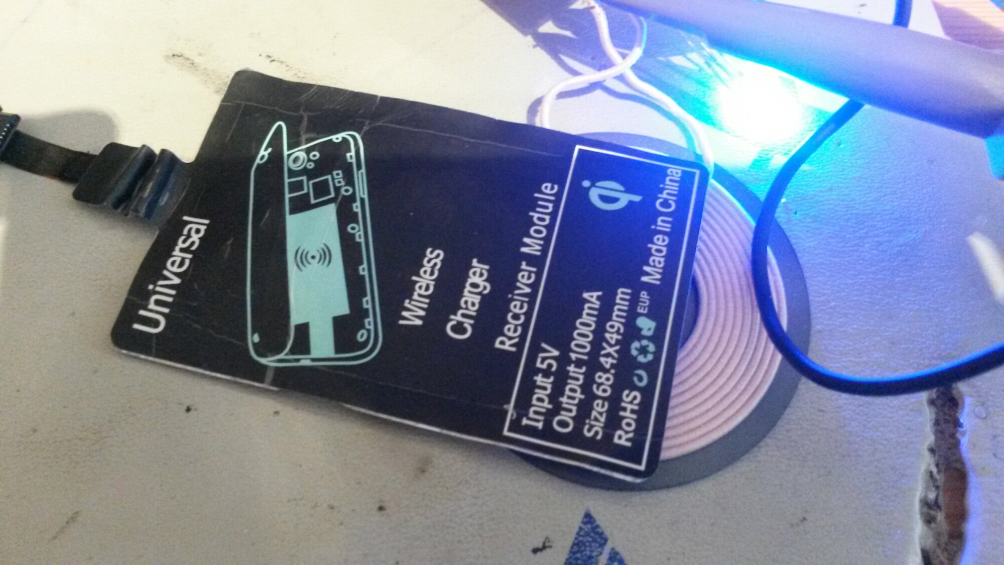
When something to charge continuous signal
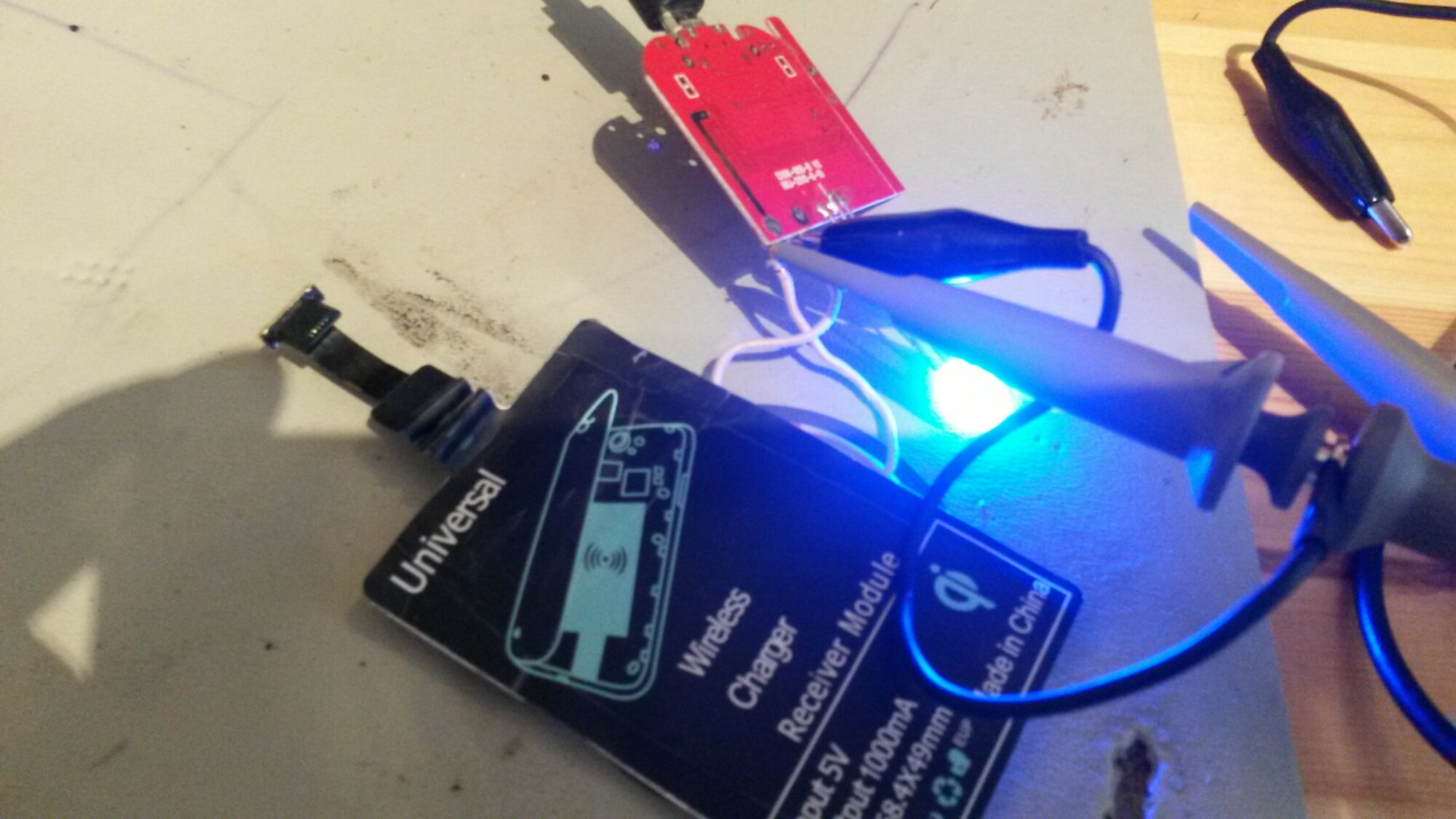
When receiver somewhat off optimal location the transmitter increases power to compensate more losses
Magnetic field measurement with 6 turns test coil
5 Comments
Tomi Engdahl says:
What happens when two QI chargers are pressed face to face.
https://www.youtube.com/watch?v=PCEDcxDshGQ
I was wondering what would happen if two QI chargers were pressed face to face with one powered and the other not. The active unit pulsed because it was not getting a response from a receiver, but the pulses were picked up by the inactive transmitter and made its indicator LED blink. It didn’t do any harm to either unit.
Tomi Engdahl says:
Playing about with a couple of QI inductive chargers and receiver.
https://www.youtube.com/watch?v=p-so2Pm7lWI
was wondering how efficiently the inductive phone chargers worked, so I got a couple of modules off ebay and a receiver plate to take to bits. They do seem to communicate with each other, rather than just pumping current into any coil that comes near.
The transmitters seemed to use what appeared to be a microcontroller controlling an H-bridge driver that then drove the coil via a paralleled cluster of capacitors. The receiver had a modest amount of circuitry in it with what appears to be a dedicated QI receiver chip, possibly by Texas Instruments.
Efficiency was 50% at best and got MUCH worse as the coils were parted.
Tomi Engdahl says:
Implementing Qi Inductive Charging Yourself
https://hackaday.com/2019/04/11/implementing-qi-inductive-charging-yourself/
Inductive charging is a technology that has promised a lot, but hasn’t quite delivered on the promise of never needing to plug in your phone again. The technology behind it is surprisingly simple though, and [Vinod.S] takes us through it all with an ATtiny13-based example.
http://blog.vinu.co.in/2019/04/qi-wireless-power-receiver-from-scratch.html
Tomi Engdahl says:
Teardown: Wireless charger boosts output, alters orientation
https://www.edn.com/design/consumer/4462478/Teardown–Wireless-charger-boosts-output–alters-orientation?utm_content=buffere9501&utm_medium=social&utm_source=twitter.com&utm_campaign=buffer
Tomi Engdahl says:
Easy DIY wireless strobing LED light
https://www.youtube.com/watch?v=g6rI5PJLtx8
A very simple project that allows you to pulse LEDs with no wiring or battery.
The project uses a QI wireless charger to power some LEDs with nothing more than a coil of wire.
Viewer comments:
If you put a capacitor across the coil (probably 1-10nf) so it resonates with the Qi charger frequency, it will work at a much longer range – may also work better with one LED as this lets the resonance build up more over the previous half-cycle
This reminds of a small circuit I made where I made a guitar shaped PCB and wound copper wire around it (2000 turns) and soldered 2 smd leds to the end and later potted it in hotglue. Yours has turned out far better than that even with no resin. Mine was made a few years ago when I was still a starter in electronics (still am, but a tiny bit better). The blue tack tric is also really neat since all people don’t have helping hands. And mine used both LEDs in parallel so it only turns on every half cycle of the output AC just like in yours.
I would expect the closer the tuned value (or harmonic) of the coil/LED network is to the operation frequency of the charging pad (I think it’s in the range ~100-200 kHz) the more energy would be transferred and the brighter the LED’s. Maybe the main difference between the 10 turns and 20 turns coil