NanoVNA is very tiny handheld Vector Network Analyzer (VNA). A vector network analyzer (VNA) is an instrument that can be used to measure antenna or coax parameters such as SWR, impedance and loss. It can also be used to characterize and tune filters. It is a very useful tool to have if you are building and tuning home made antennas, filters or other RF circuits.
Earlier VNAs have been considered to be be very expensive instruments costing thousands or tens of thousands of dollars so they have only been available on advanced RF laboratories. But now the cost has come down. Nowadays there are cheaper alternatives available. Thank’s to NanoVNA the cost of owning a VNA has now been reduced to only US$50 thanks to the NanoVNA. The open source NanoVNA project by @edy555 and ttrftech has been around since 2016, but only recently have Chinese sellers begun mass producing the unit and selling them
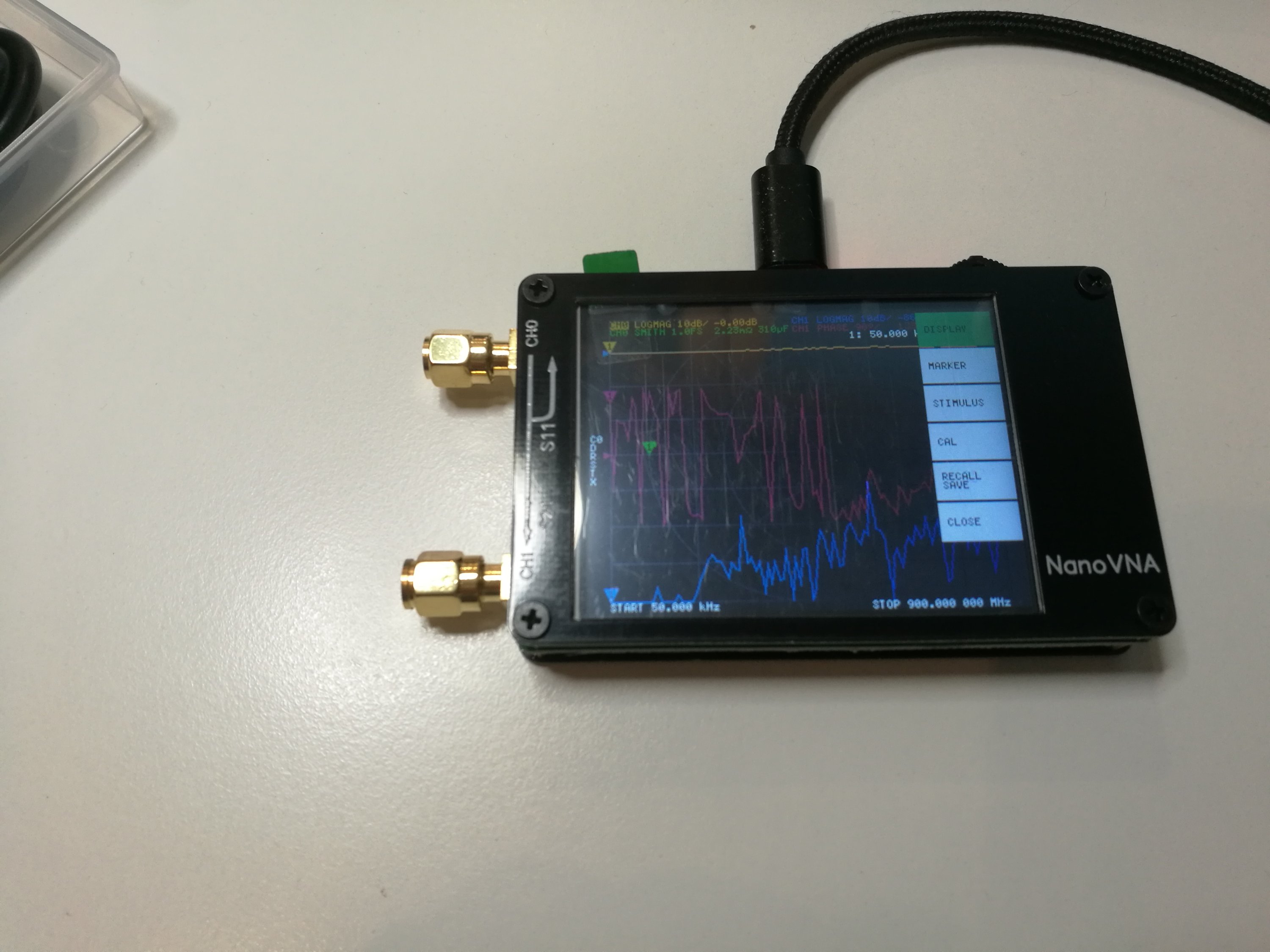
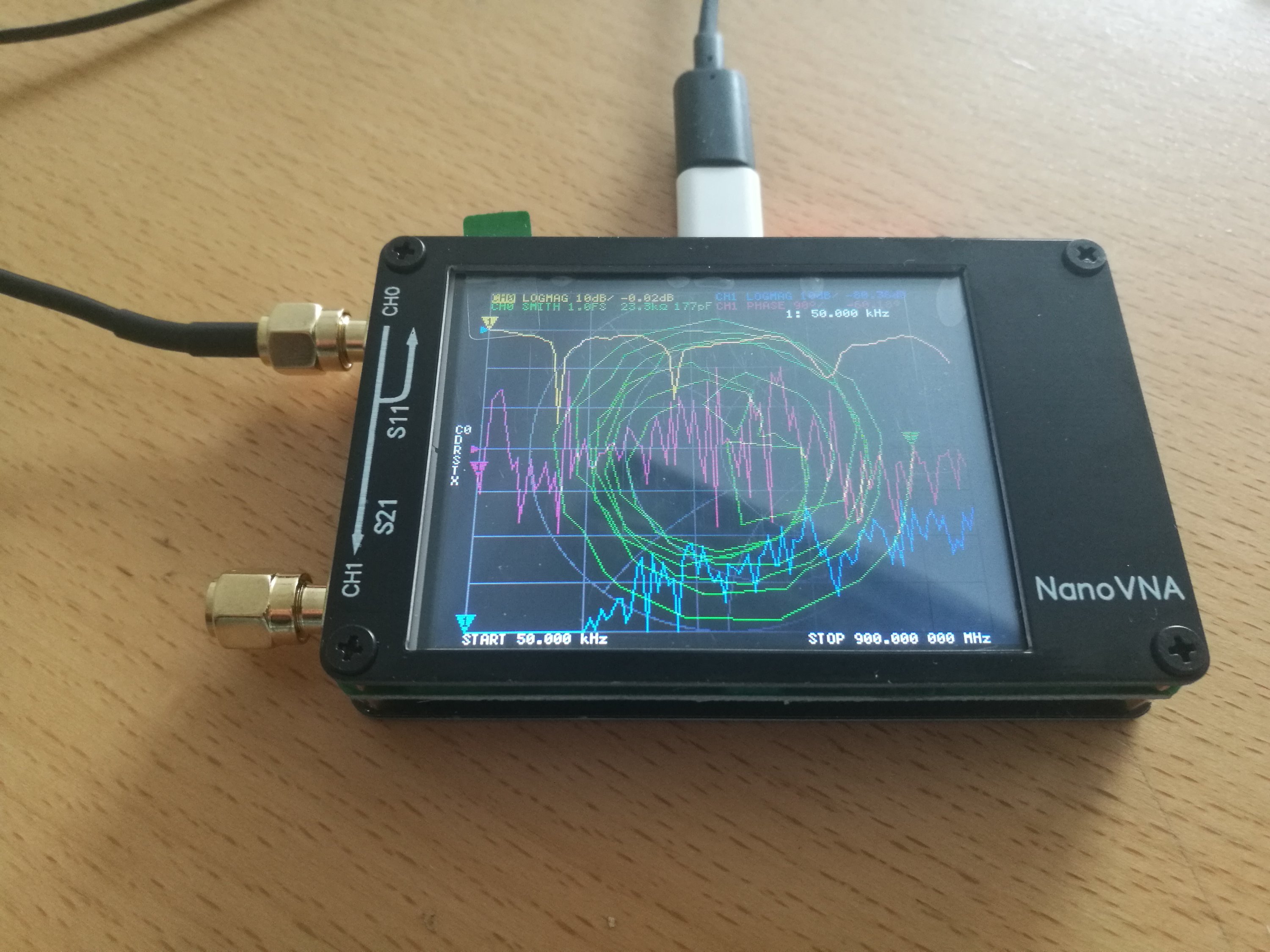
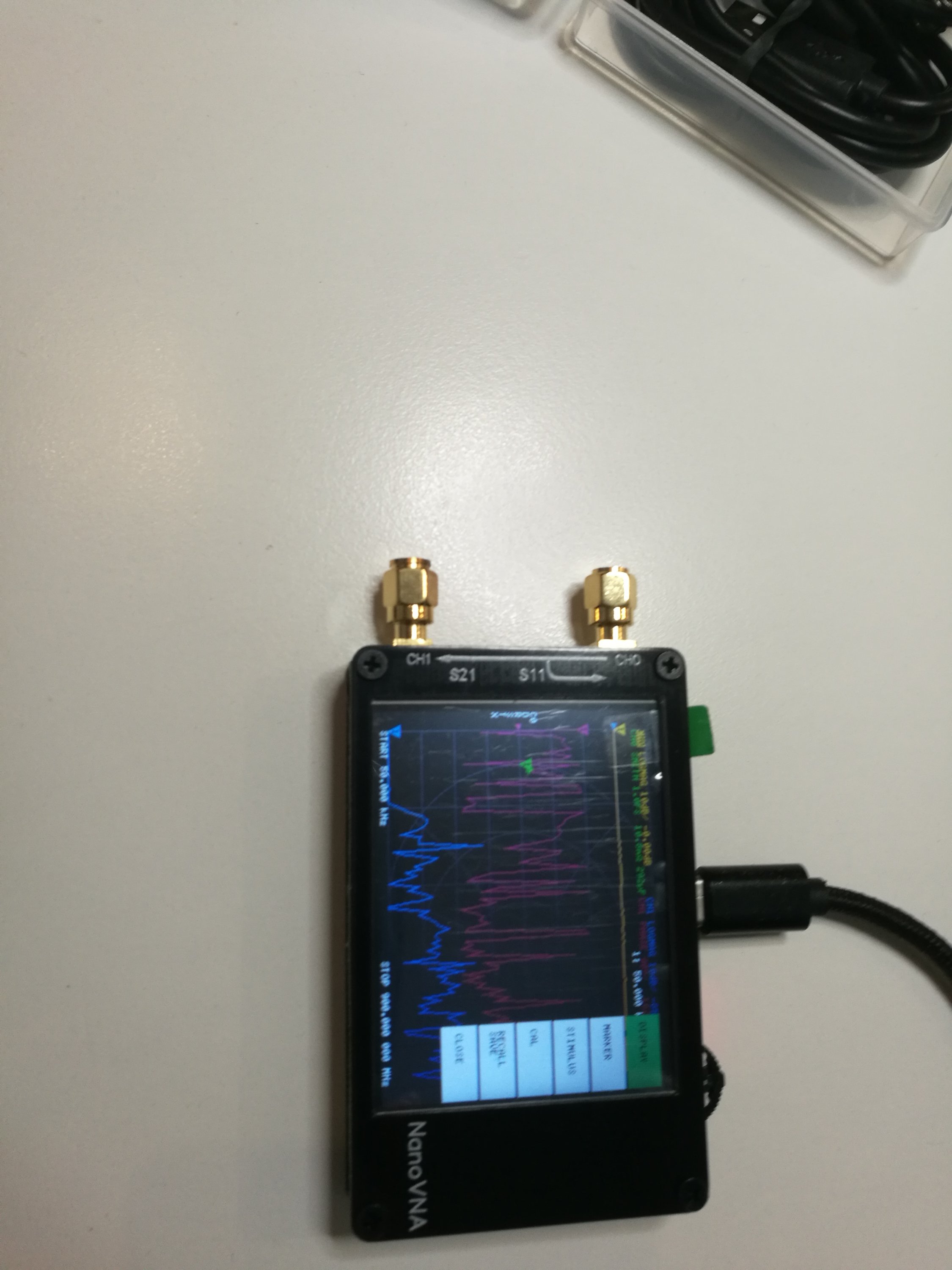
NanoVNA is advertised as a standalone device with LCD display, portable device with battery. It can also controlled with PC software.The frequency range is from 50 kHz to 900 MHz. I had earlier posted some videos on this device to http://www.epanorama.net/newepa/2019/08/11/nanovna-handheld-vector-network-analyzer-vna/
There are a ton of people selling them out of China. I ordered mine from my trusted source Banggood.com that sells one for around $65. Here is the device I received:
NanoVNA Vector Network Analyzer 50KHz – 900MHz Digital Display Touch Screen Shortwave MF HF VHF UHF Antenna Analyzer Standing Waveis a a DIY product with vector network measurement function. It includes a 2.8-inch touch screen, TX/RX measurement, can determine the complete S11 and S21 parameters (claimed that can be modified to measure S12 and S22). Here is the technical data from product page:
● RF output: -13dbm (maximum -9dbm)
● Measurement range: 70dB (50kHz-300MHz), 60dB (300M-600MHz), 50dB (600M-900MHz) enable extended firmware);
● Port SWR: < 1.1
● Display: 2.8 inch TFT (320 x240)
● USB interface: USB type-C communication mode: CDC (serial)
● Power: USB 5V 120mA, can use battery powered, maximum charging current 0.8A (battery Not included )
● Number of scanning points: 101 (fixed)
The firmware for the device is open source and available at https://github.com/ttrftech/NanoVNA. The device schematics are also available there.
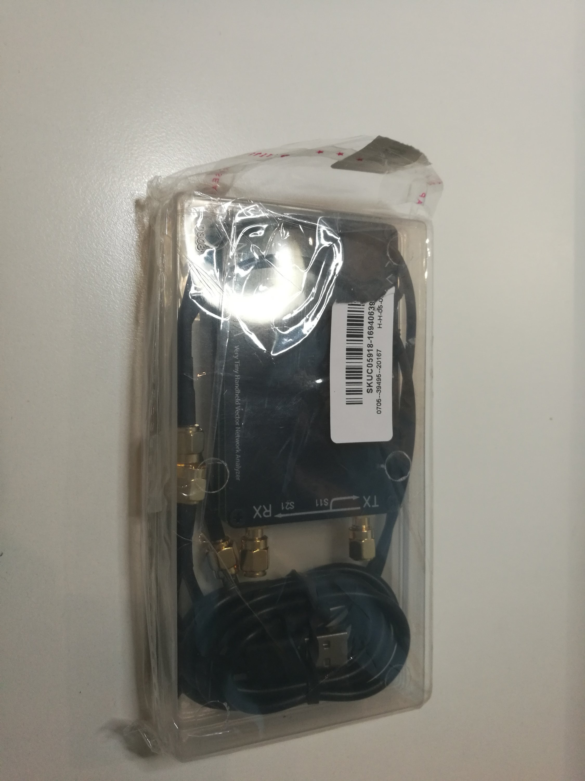
The product package included NanoVNA device, USB Type-C data cable, two 30mm SMA male to male cable and test connectors, one SMA female to female connector and calibration parts (SMA connector with open, short circuit and 50 ohms terminator). Everything came in a nice plastic box that is useful for storing and transporting all the parts.
There is also PC software to work with this device. The device home page had software package that included NanoVNA v1.01 software did not work for me. After some Googling I found a discussion on the problem with this software on some countries (it was . vs , issue on number presentation) and the discussion recommended to download NanoVNA v1.03 from https://drive.google.com/drive/folders/1IZEtx2YdqchaTO8Aa9QbhQ8g_Pr5iNhr. NanoVNA v1.03 worked for me.
There were also some Python software code that I did not try this time.
Other issues:
The device supports rechargeable LiPo batteries, but the batteries are not included on the model I bought because of the safety of international transportation. I also liked to have the LiPo battery installed on my device. The device has battery charging circuitry, so installing suitable LiPo battery should make it very portable instrument (500mAh battery should give offline for 2 hours). Getting suitable LiPo battery and installing it is for another article.
Sometimes I feel that it would be nice if this device has a full case. I saw one 3D printable case for NanoVNA at Thingverse. I have downloaded the files, but I have not yet had access to suitable 3D printer to print it.
Related postings:
http://www.epanorama.net/newepa/2019/08/11/nanovna-handheld-vector-network-analyzer-vna/
https://www.rtl-sdr.com/reviews-of-the-nanovna-an-ultra-low-cost-50-vector-network-analyzer/
http://www.bbrc.info/articles/nanovna
https://groups.io/g/nanovna-users
https://brainwagon.org/2019/09/02/first-test-of-the-nano-vna-on-my-beacon-antenna/
https://github.com/ttrftech/NanoVNA
https://hexandflex.com/2019/08/31/getting-started-with-the-nanovna-part-1/
https://mtmotorstables.blogspot.com/2019/08/reviews-of-nanovna-ultra-low-cost-50.html
Getting the device:
If you are interested in getting one, use this link https://www.banggood.com/NanoVNA-Vector-Network-Analyzer-50KHz-900MHz-Digital-Display-Touch-Screen-Shortwave-MF-HF-VHF-UHF-Antenna-Analyzer-Standing-Wave-p-1471576.html?p=27131452996820140438 to get the version I got. It seems that the same web shop has also a slightly cheaper version (white color) in pre-order at https://www.banggood.com/NanoVNA-Vector-Network-Analyzer-50KHz-900MHz-Digital-LCD-Display-HF-VHF-UHF-Antenna-Analyzer-Standing-Wave-USB-POWER-p-1549963.html?p=27131452996820140438
161 Comments
Tomi Engdahl says:
Is it possible to use the nanoVNA as a spectrum analyser?
https://www.reddit.com/r/HamRadio/comments/hukuu6/is_it_possible_to_use_the_nanovna_as_a_spectrum/
TINYSA IS A $49 SPECTRUM ANALYZER
https://hackaday.com/2020/09/01/tinysa-is-a-49-spectrum-analyzer/
The NanoVNA made network analyzers cheap enough for almost everyone. Now you can get a $49 spectrum analyzer to go with it. Is it worth it? Watch [IMSAI Guy]’s video after the break for his opinion. From the tinySA.org website:
Spectrum Analyzer with two inputs, high-quality MF/HF/VHF input for 0.1MHZ-350MHz, lesser quality UHF input for 240MHz-960MHz.
Switchable resolution bandpass filters for both ranges between 2.6kHz and 640kHz
Color display showing 290 scan points covering up to the full low or high-frequency range.
Input Step attenuator from 0dB to 31dB for the MF/HF/VHF input.
When not used as Spectrum Analyzer it can be used as Signal Generator, MF/HF/VHF sinus output between 0.1MHZ-350MHz, UHF square wave output between 240MHz-960MHz.
A built-in calibration signal generator that is used for automatic self-test and low input calibration.
Connected to a PC via USB it becomes a PC controlled Spectrum Analyzer
Rechargeable battery allowing a minimum of at least 2 hours portable use
Tomi Engdahl says:
https://github.com/nanovna/NanoVNA-QT
Tomi Engdahl says:
https://www.eevblog.com/forum/rf-microwave/nanovna-custom-software/msg2668785/#msg2668785
https://www.eevblog.com/forum/rf-microwave/nanovna-custom-software/275/
Tomi Engdahl says:
Use NanoVNA-F’s TDR function to measure the physical length of the cable and RF Demo Kit experiment
https://www.youtube.com/watch?v=24QkBN-W9n4
Tomi Engdahl says:
Scattering parameters
https://en.wikipedia.org/wiki/Scattering_parameters
Scattering parameters or S-parameters (the elements of a scattering matrix or S-matrix) describe the electrical behavior of linear electrical networks when undergoing various steady state stimuli by electrical signals.
The parameters are useful for several branches of electrical engineering, including electronics, communication systems design, and especially for microwave engineering.
Many electrical properties of networks of components (inductors, capacitors, resistors) may be expressed using S-parameters, such as gain, return loss, voltage standing wave ratio (VSWR), reflection coefficient and amplifier stability. The term ‘scattering’ is more common to optical engineering than RF engineering, referring to the effect observed when a plane electromagnetic wave is incident on an obstruction or passes across dissimilar dielectric media. In the context of S-parameters, scattering refers to the way in which the traveling currents and voltages in a transmission line are affected when they meet a discontinuity caused by the insertion of a network into the transmission line. This is equivalent to the wave meeting an impedance differing from the line’s characteristic impedance.
Although applicable at any frequency, S-parameters are mostly used for networks operating at radio frequency (RF) and microwave frequencies where signal power and energy considerations are more easily quantified than currents and voltages. S-parameters change with the measurement frequency, so frequency must be specified for any S-parameter measurements stated, in addition to the characteristic impedance or system impedance.
S-parameters
https://www.microwaves101.com/encyclopedias/s-parameters
Tomi Engdahl says:
Characterization and DC shield resistance #tests can provide a quick check on the shielding quality and #connector bonding of test #cables #EMC
Quickly assess relative coax-cable-shielding quality
https://www.edn.com/quickly-assess-relative-coax-cable-shielding-quality/?utm_content=bufferc759e&utm_medium=social&utm_source=edn_facebook&utm_campaign=buffer
Assuming you have Wi-Fi access points and computers nearby, scanning in max hold mode, poor quality shielded cable should be easily identified by observing an increasing level of received signals. Well-shielded cables will show relatively little signal
Another important characteristic is a low DC resistance between each connector shield. Measuring the DC resistance also makes a gross check on shield conductivity and shield to connector bonding and is easy to do. Simply set a DC power supply to current limit at 1 amp and connect the output to each end of the cable under test
Any spectrum analyzer should work well to characterize relative shielding properties of single coaxial cables
Summary
Poorly-shielded cables used for radiated emissions compliance testing can be quite risky and usually leads to emissions failures. Characterization tests such as the simple shielding test using commonly available Wi-Fi and Bluetooth signal sources, as well as DC shield resistance tests, can provide a quick check on the shielding quality and connector bonding of proposed test cables.
I was happy to have discovered the bad BNC patch cable
Tomi Engdahl says:
#318: NanoVNA comparison measuring a duplexer – NanoVNA-H4 and SAA-2N
https://www.youtube.com/watch?v=GipCVEsiqXc
Is the NanoVNA suitable to measure/adjust a typical antenna duplexer? This video compares the NanoVNA-H4 and the SAA-2N VNAs with a professional VNA (Tektronix TTR506A). Will the limited dynamic range of the NanoVNA get in the way of making a good measurement, or limit the ability to adjust the duplexer? Watch and find out…
Post Production Note: I received an email from one of the developers of the “V2″ platform, and he informed me that while they intentionally open-sourced the design in order to give users more choice, there have been at least one clone maker that has manipulated the market in various ways (false rankings, and selling at cost) which does a discredit to the original developers. This is the case with the SAA-2N featured in this video. The official website for the V2, from the original developers, is https://nanorfe.com/nanovna-v2.html
Please consider this when making your choice about what V2 hardware to buy.
Tomi Engdahl says:
#314: How to use the NanoVNA to sweep / measure an antenna system’s SWR and optimize its tuning
https://www.youtube.com/watch?v=xa6dqx9udcg
#368 NANOVNA Return Loss vs VSWR
https://www.youtube.com/watch?v=0GrMIGAyFUE
Tomi Engdahl says:
NanoVNA measuring velocity factor and cable length
https://www.youtube.com/watch?v=aWvPB299U60
Tomi Engdahl says:
NanoVNA for antenna testing
https://www.youtube.com/watch?v=uA1HyScp96w
Tuning antenna with nanoVNA
https://www.youtube.com/watch?v=b2D_c3c8rfw
Tomi Engdahl says:
#361 NANOVNA measuring inductance in a 50ohm load
https://www.youtube.com/watch?v=pXjFS2MhuqI
Tomi Engdahl says:
How to determine the value of a capacitor or inductor using a network analyzer
https://www.youtube.com/watch?v=scwgbxWHTQI
Tomi Engdahl says:
nanoVNA – Coaxial Cable Measurement Methods (Characteristic Impedance and Cable Loss) – VE6WGM
https://www.youtube.com/watch?v=G66_iqOu-Bs
1. Calibrating the nanoVNA
2. The Smith Chart – Briefly (Begins at 8:24)
3. Measuring the characteristic impedance of coax cable. (Begins at 11:46)
4. Measuring coax cable loss. (Begins at 22:34) *Correction: At 23:34 I stated that the nanoVNA has a directional coupler. I have since discovered that this is not accurate information. The nanoVNA actually uses a bridge to make it’s measurements.
Tomi Engdahl says:
#317: NanoVNA Port Extension using the Electrical Delay setting
https://www.youtube.com/watch?v=bEPUePy_buM
If you need to use adapters, fixtures, cables, etc. to connect to you DUT, you may need to apply a port extension to move the calibration plane to the DUT end of these “additions”. This video discusses what a port extension is, why you might need it, and how to do it on the NanoVNA.
Comments:
How does adding this delay differ from just doing a new calibration to include the extra connector? I thought the cal took the extra length into account.
Performing the calibration at the far end of the added connector, fixture, etc. is the PREFERRED thing to do, this will take the extra length into account. You would use Port Extension only when it isn’t possible to do this (maybe due to mis-matched connector types, etc.).
Can you tell me what kind of new stainless steel connectors you added to your VNA to protect the ports?
They’re a pair of m-f adapters (connector savers) from Mini-Circuits. Calibration was done after adding them.
NanoVNA-F soon and there is a beta firmware to increase the frequency to 2.7gigs. Cheaper kits may be okay up to 900 M but calibration may be off at 2.7. Thanks!
Tomi Engdahl says:
nanoVNA – Characteristic Impedance Measurement Methods – Testing 75 Ohm Coax – VE6WGM
https://www.youtube.com/watch?v=8c13PPA51zs
1. Testing the methods described in the previous video to measure coax cable characteristic impedance using the nanoVNA… this time on 75 ohm coax cable.
2. How to measure coax cable length and impedance using time domain reflectometry. (Begins at 4:56)
Tomi Engdahl says:
NanoVNA and Preamplifier 144 MHz
https://www.youtube.com/watch?v=29yTVG8lg7s
Measurement of the transmission curve, gain, bandwidth of a 144 MHz preamplifier.
Because overdriving use damping devices 10 or 15 dB if nessesary!
Tomi Engdahl says:
#270: Tune a Duplexer with a Spectrum Analyzer + Tracking Gen or VNA
https://www.youtube.com/watch?v=tf5h_wz9G2o
Suojakaapit sinulle
Laminaarikaapit, Luokan 2 suojakaapit, Vetokaapit, Suodatinvetokaapit, Hanskakaapit
laboline.fi
#248: Tune Bandpass Cavity Filter using Return Loss w Directional Coupler
https://www.youtube.com/watch?v=vVuMYCdlsZw
Tomi Engdahl says:
#316: Use NanoVNA to measure coax length – BONUS Transmission Lines and Smith Charts, SWR and more
https://www.youtube.com/watch?v=9thbTC8-JtA
Tomi Engdahl says:
#024 NanoVNA H4 – Review
https://www.youtube.com/watch?v=GiYyp1xnrdc
Quick and Clumbsy, review of the NanoVNA H4
NanoVNA-H4 Made Easy – HAM Radio – TheSmokinApe
https://www.youtube.com/watch?v=ay58sp8VaNM
In this video we take a look at the NanoVNA-H4 and use it to perform a quick analysis on an End Fed antenna. We will also run through simple configuration and calibration settings.
Tomi Engdahl says:
#315: How to use the NanoVNA to measure a low-pass filter
https://www.youtube.com/watch?v=F17mN5uuzGY
Tomi Engdahl says:
#365 NANOVNA resistance measurement accuracy
https://www.youtube.com/watch?v=17AU24KtYkg
checking resistance measurements
Tomi Engdahl says:
nanoVNA – Characteristic Impedance Measurement Methods – Testing 75 Ohm Coax – VE6WGM
https://www.youtube.com/watch?v=8c13PPA51zs
Tomi Engdahl says:
#499 NANOVNA Grounded Coax
https://www.youtube.com/watch?v=rWDES6j6boo
Include earth ground in your measurement if appropriate
Tomi Engdahl says:
#574b Coaxial Switch Isolation Measurement
https://www.youtube.com/watch?v=1vrWohYQzYw
Tomi Engdahl says:
#576 NANOVNA Measuring an Amplifier
https://www.youtube.com/watch?v=JdfdOlBz4vI
WARNING: do not input more than 0dBm (1mW) power into the NANOVNA
Using the NANOVNA to measure the gain the frequency response of a small amplifier
Tomi Engdahl says:
Which NanoVNA Should I buy? – TheSmokinApe
https://www.youtube.com/watch?v=xNNtM_mUAqc
In the “Lid Tips” series where we discuss topics of intereast to Ham or Amateur Radio Operators. In this episode we discuss my buddy Stan and his desire to purchase a NanoVNA.
Tomi Engdahl says:
#467 NANOVNA Filter Sweep Compared to HP8921a
https://www.youtube.com/watch?v=dmCw-iKLd44
RF filter transmission vs frequency measurement with NANOVNA and HP8921a
NANOVNA used as a Scalar Network Analyzer
HP8921a used as a Spectrum Analyzer with Tracking Generator
Tomi Engdahl says:
NanoVNA Presentation by David Houser KG5RDF
https://www.youtube.com/watch?v=y7PEDRN1PpY
Tomi Engdahl says:
#316: Use NanoVNA to measure coax length – BONUS Transmission Lines and Smith Charts, SWR and more
https://www.youtube.com/watch?v=9thbTC8-JtA
TWO Part video: Part 1 shows how to use the Transform function in the NanoVNA to measure coax length or distance to fault. Part 2 (starting at about 4:40) digs a bit deeper into the effects of a transmission line on the observed impedance and SWR, how this is represented on the Smith Chart, and some of the “magic” of quarter-wavelength long lines.
Tomi Engdahl says:
https://coppermountaintech.com/passive-rf-system-measurements-in-a-strong-rf-environment-using-an-amplifier-with-a-2-port-vna/
Tomi Engdahl says:
https://etn.fi/index.php/13-news/11322-differentiaalisen-kohinaluvun-mittaus-piirianalysaattorilla
Tomi Engdahl says:
#319: Measuring Crystals with NanoVNA and other tools
https://www.youtube.com/watch?v=G9zZRNzhsEE
This video shows several methods for measuring crystal parameters using the NanoVNA and other tools.
Tomi Engdahl says:
#317: NanoVNA Port Extension using the Electrical Delay setting
https://www.youtube.com/watch?v=bEPUePy_buM
The user calibration, described in video #313 (https://youtu.be/x-tbvAbh9jk), establishes a calibration or reference plane for the complex reflection/impedance measurement on the VNA. If you need to use adapters, fixtures, cables, etc. to connect to you DUT, you may need to apply a port extension to move the calibration plane to the DUT end of these “additions”. This video discusses what a port extension is, why you might need it, and how to do it on the NanoVNA.
https://www.qsl.net/w2aew/youtube/NanoVNA_Port_Extension.pdf
Tomi Engdahl says:
#313: Why a VNA needs to be calibrated | how to calibrate a nanoVNA
https://www.youtube.com/watch?v=x-tbvAbh9jk
This video describes why a “user” calibration is needed when using a VNA (vector network analyzer), what systematic errors it corrects for, what is meant by a measurement plane or calibration plane, and finally an example of how the calibration is performed on a nanoVNA. Note from this video can be found here:
Tomi Engdahl says:
https://www.qsl.net/w2aew/youtube/why_calibrate_a_VNA.pdf
Tomi Engdahl says:
#584 NANOVNA Using Clip Leads
https://www.youtube.com/watch?v=s82P5btDfeU
Episode 584
I will show how to use the VNA with clip leads and calibrate. Useful in measuring and troubleshooting circuits.
Tomi Engdahl says:
Practical RF Filter Design and Construction
https://www.youtube.com/watch?v=1sq8Cvju2Oo
An introduction to practical RF filter design by building, testing, and tweaking a 137MHz bandpass filter suitable for NOAA APT satellite reception. Additional references and reading materials at:
http://www.analogzoo.com/2017/03/practical-rf-filter-design/
Tomi Engdahl says:
https://hackaday.com/2017/03/30/real-world-rf-filter-design-and-construction/
Tomi Engdahl says:
https://www.electronics-notes.com/articles/radio/rf-filters/understanding-rf-filters-basics-tutorial.php
Tomi Engdahl says:
Measurements on RF and AF Filters
https://cdn.rohde-schwarz.com/pws/dl_downloads/dl_application/application_notes/1ma243_filter_meas_value_instr/1MA243_1e_Filter_Meas_Value_Instr.pdf
Tomi Engdahl says:
Standard DIY testing Circuit Kit
https://www.temwell.com/msg/msg55.html
Tomi Engdahl says:
http://www.kb5tx.org/Presentations/NanoVNA-F.pdf
HOW DOES A NANOVNAWORK?
To keep the design low cost, the NanoVNAdoes not provide an RF signal path to Port 2. Thus it only measures S11 (match), and S21 (gain or loss). However, we can still measure S22 and S12 by simply flipping around the Device Under Test (DUT).
VNACALIBRATION•Remember that a VNA not only measures signal amplitude, but it also measures phase relative to its internal RF source. In order to measure the true impedance or time delay or cable length (etc.) of a test item, we first must establish a phase/amplitude reference plane. This is done with a procedure called an SOLT calibration (Short, Open, Load, Through). •Procedure:•Set a wide frequency span in the STIMULUS menu,say 1-1200 MHz•Go to CAL menuand connect OPENstandard to Port 1.•Use a stylus to select the OPEN tab. The VNA will beep and the tab lettering will invert color to indicate that the calstep is complete.•Repeat for SHORTand LOADstandards.•With the LOADstill attached to Port 1, press the ISOLATION tab•Disconnect LOADstandard, and connect short coax jumper provided between Port 1 and Port 2.•Press the THROUGHtab. Then press DONE. Remove the short coax jumper.•What happens now? You have set the measurement reference plane to Port 1. The VNA will measure true complex S-parameters relative to this location.•What if it isn’t convenient to attach a load directly to the Port 1? The reference plane can be extended with a length of coax cable. Repeat the CAL procedure by attaching CAL standards to the end of a convenient length cable connected to Port 1. The reference plane will then exist at the end of the cable instead of at Port 1.•Amplitude Only: if all you care about is VSWR or frequency response then reference phase is not important (amplitude only). You can still calibrate at Port 1, then attach your antenna coax to measure VSWR, or attach a filter with short coax sections and measure response, etc.
USES AROUND THE SHACK•Sweep any ham band up to 1300 MHz.•One port measurements (S11): •“Cantenna” or other dummy load (VSWR vsfrequency)•Antennas (VSWR vsfrequency)•Coax cable length (TDR)•Table of standard coax types built in to software!•Coax cable distance to fault (TDR)•Components (inductance, capacitance, resistance)•Home brew RF circuits (impedance matching aid)•Tuned circuits/loop antenna (find resonances)•Two port measurements (S11, S21) :•Bandpass/lowpass/highpass/notch filters (frequency response)•Filters for Field Day!•Repeater duplexer (insertion loss, isolation)•Attenuators (return loss and insertion loss vsfrequency)•Low power RF amplifiers (gain, reverse gain, return loss vsfrequency)•Signal source –can be set to a single CW RF frequency
Tomi Engdahl says:
Measurements on magnetic cores
https://www.qsl.net/in3otd/electronics/magnetics/magnetics.html
Sometimes one finds some magnetic core in the junkbox, at hamfests or dismantling electronic equipment and wonders if these could be useful for some projects.
Knowing the core material permeability and losses over frequency is of course the first step to understand of those cores can be useful for some RF applications or were intended for other applications.
Tomi Engdahl says:
https://qrznow.com/nanovna-port-extension-using-the-electrical-delay-setting/
Tomi Engdahl says:
https://www.hackster.io/news/qrp-labs-filter-adapter-for-nanovna-7ed8ca1ff4a4
Tomi Engdahl says:
Port Extension
https://youtu.be/bEPUePy_buM
Tomi Engdahl says:
If you are just starting out with a NanoVNA or considering purchasing one you will enjoy this video on VNA basic principles. It uses the V2 but the concepts are applicable to all NanoVNA products.
https://youtu.be/_pjcEKQY_Tk
Tomi Engdahl says:
done a lot of testing of my NanoVNA. Properly calibrated it works very well and is very accurate below 300 MHz. With proper test jigs It can accurately measure components like capacitors and inductors.
Tomi Engdahl says:
https://it9ybg.blogspot.com/2020/11/antscope2-rigexpert.html
Tomi Engdahl says:
Upgrade NanoVNA use DFU
https://nanovna.com/?page_id=103
1.DFU is a SW is for programming the STM32 via the USB (UM0412)
The package contains all binaries and source code for DfuSe USB device firmware upgrade (DFU) software, including the demonstration, debugging GUIs and protocol layers.
https://www.st.com/en/development-tools/stsw-stm32080.html?s_searchtype=keyword
It includes the DFU driver compatible with the latest Microsoft®OS.