An adjustable regulated power supply is a necessary tool for an electronics laboratory. Here is a laboratory power supply 2.7-30V up to 4A I built has worked for 30 years ago and still going strong. Its function is to supply a stable voltage set by the voltage control potentiometer up to the current set by current limiting control. The current limiting is adjustable in 0-1A or can be set to fixed value of around 4A. There are old recycled voltage and current meters and also a new digital voltage meter add-on.
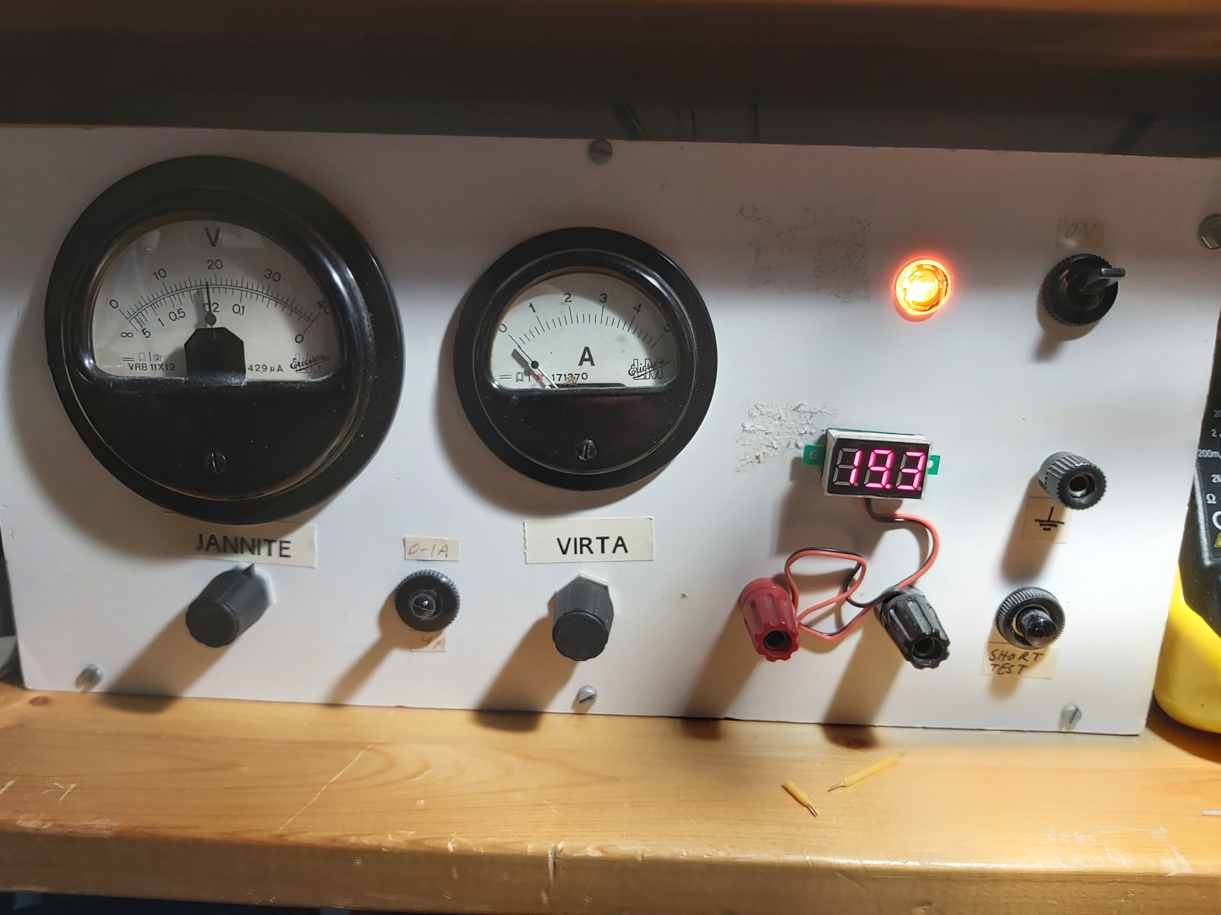
On the front panel the Finnish language labels JANNITE means voltage and VIRTA means current.
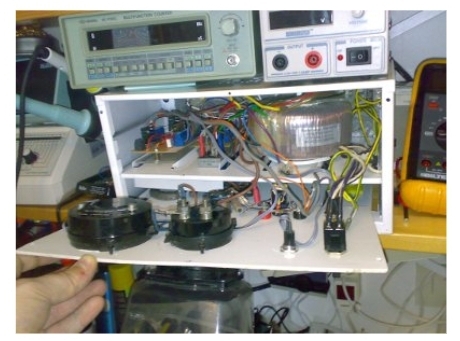
Take a look at the wiring inside:
Here I presents the most important part of my mains power supply circuit. The circuit diagrams are my hand-drawn circuit diagrams I made at the time. Here are the circuit diagrams of the most important parts.
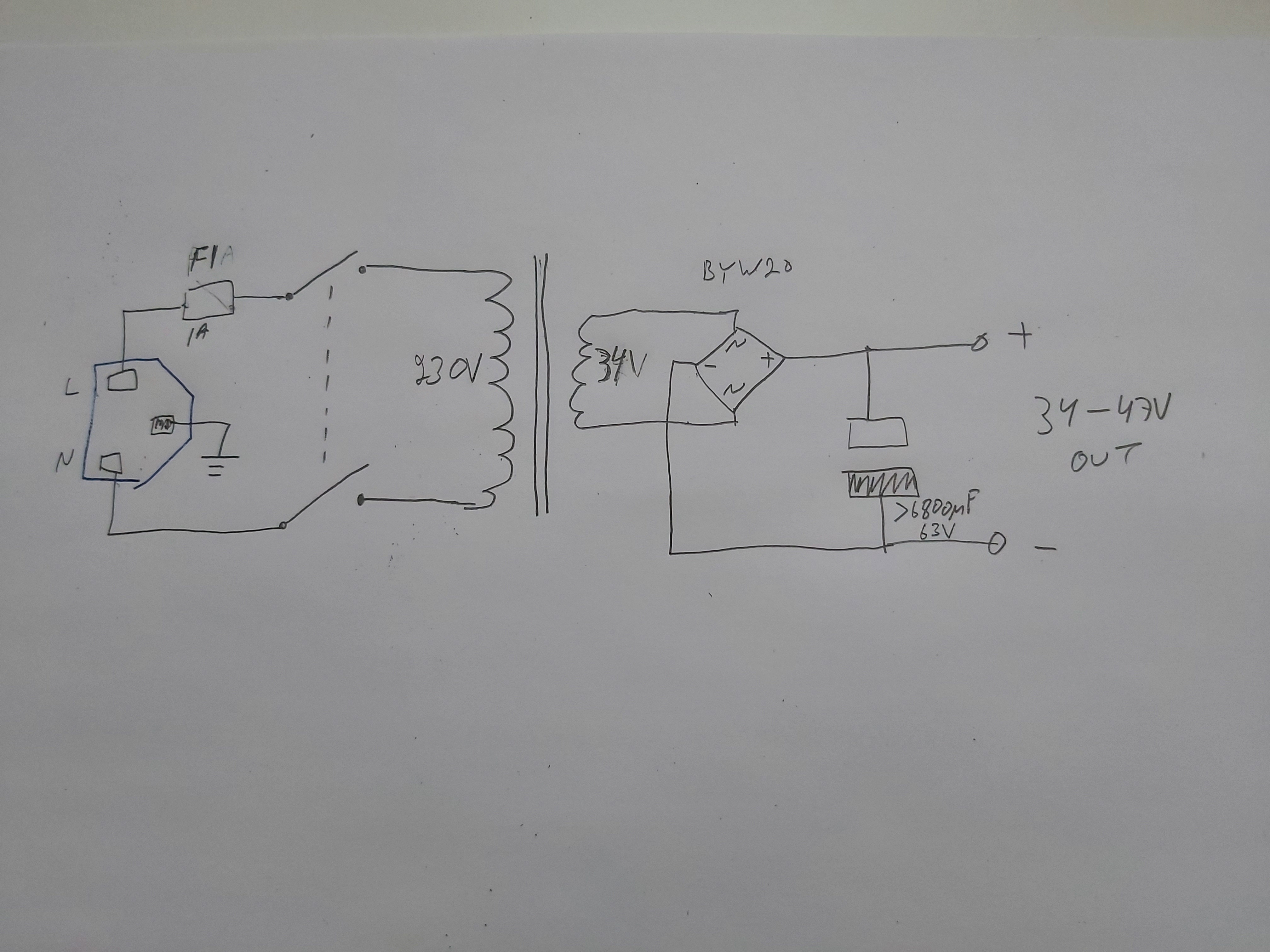
The mains transformer circuit converts unregulated AC (Alternating Current) into a DC voltage that can be fed to the regulating circuitry. The transformer I used was a big toroid transformer designed to convert 230V AC to 48V AC, but it was converted to give somewhat lower voltage with suitable tap on the secondary. In the primary side I had mains input connector with fuse and mains power switch that cuts power from both live an neutral wires. With the help of a rectifier bridge the AC electrical power is converted into DC. The voltage is smoothed with a big electrolytic capacitor.
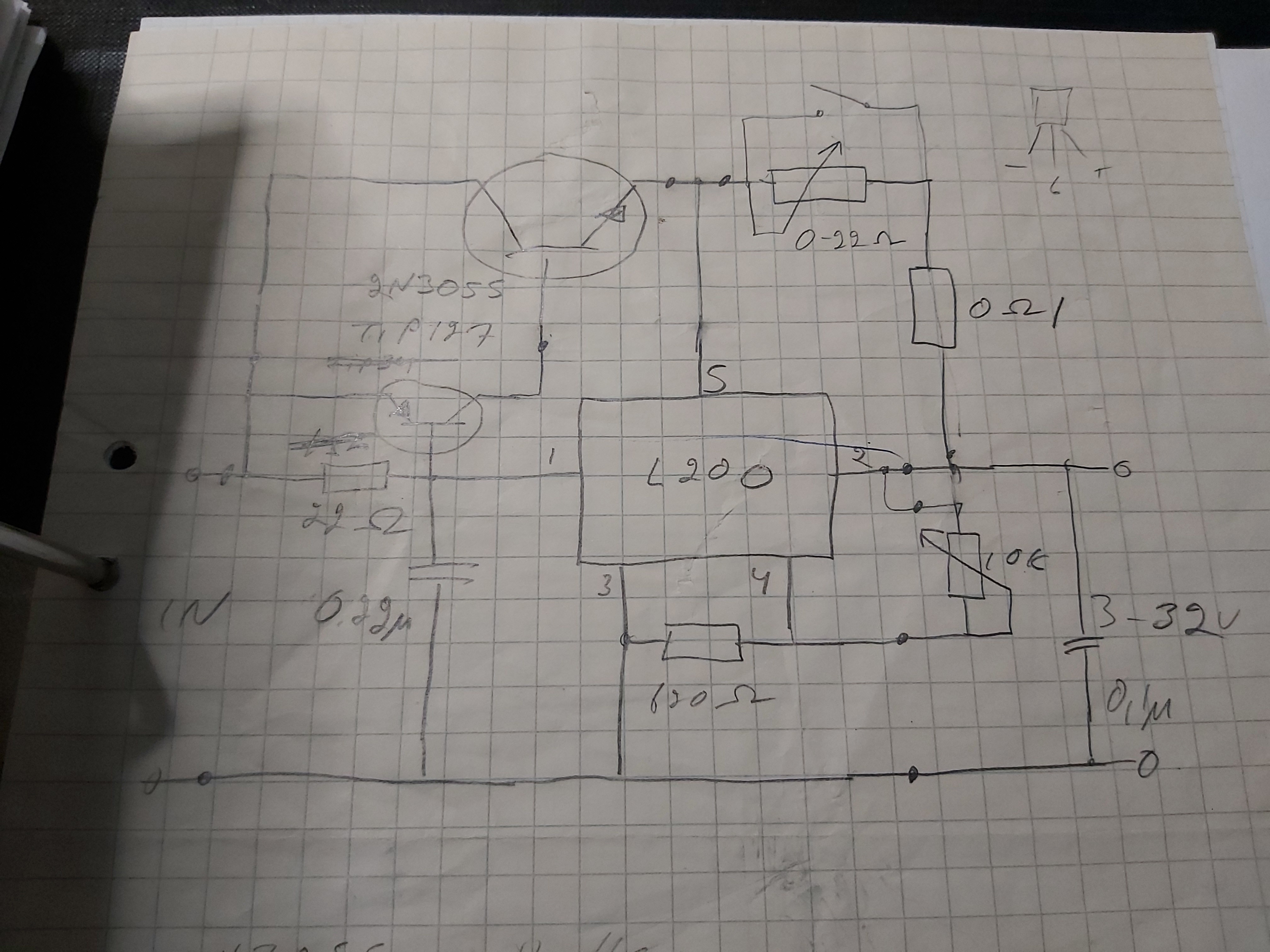
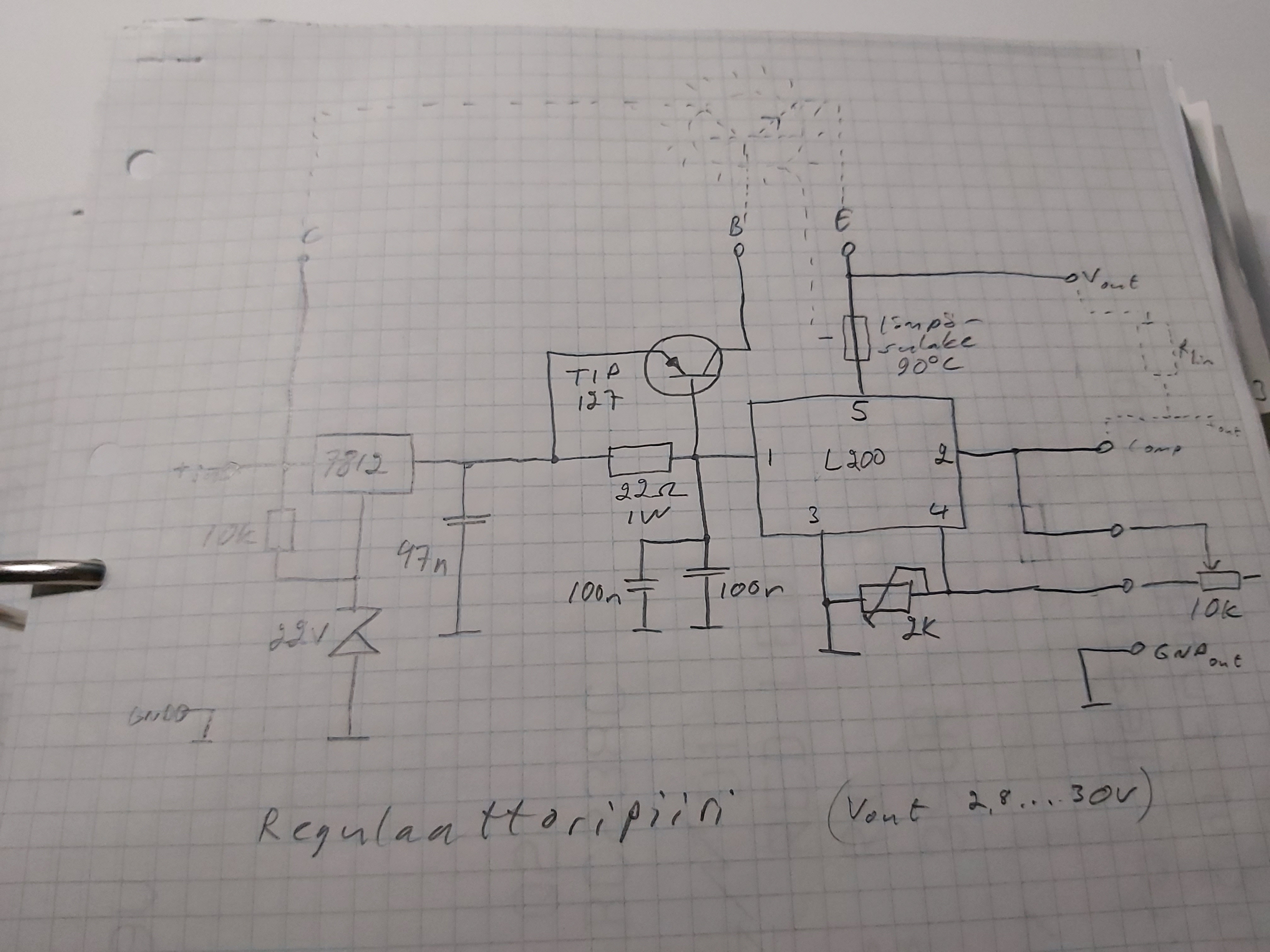
The regulation of he output voltage and current is done using a circuit based on L200 regulator chip from ST. The L200 is a positive variable voltage regulator which includes a current limiter and supplies up to 2 A at 2.85 to 36 V. The output voltage is fixed with two resistors or, if a continuously variable output voltage is required, with one fixed and one variable resistor.
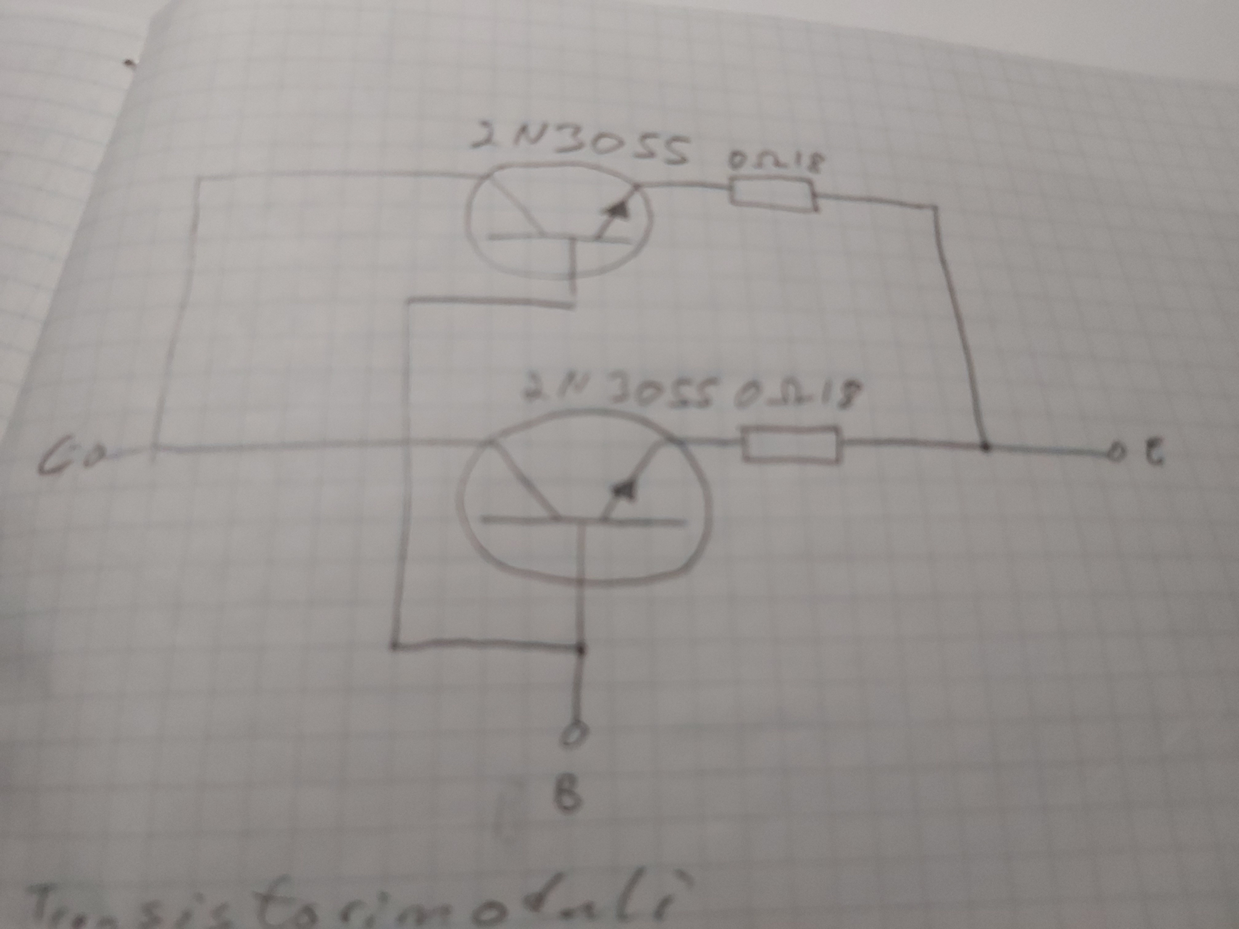
Because the maximum current of L200 regulator is 2A and there is a limited amount of power loss it can handle, I had to boost the output current of L200 with a transistor. A traditional L200 boosting is done with one PNP power transistor, but in my circuit I used one PNP transistor which controller an NPN power transistor (I wanted to use 2N3055 power transistors I had). Here is the basic circuit I planned to use first. The output voltage is controlled with 10 kohms potentiometer and output current is controlled with 20 ohms power potentiometer (that can handle up to few watts of power loss).
The L200 starts to limit output current when the voltage drop over the current limiting control resistor reaches around 0.45V. This resistor is built by putting a 20 ohm potentiometer in series with 0.1 ohm resistor, so I had nice output current control range. The 0.1 ohm resistor limits the maximum output current (when potentiometer is zero ohms) to around 4-4.5A. The circuit is intentionally limited to this current because of the rating of mains power transformer.
When I did some more research and calculations, I decided to modify this idea. A Single 2N3055 has can handle DC Collector Current 15A and Power Dissipation 115W. That 115W power dissipation could be exceeded if I push full current to lowest voltage output and I would need very good cooling to meet that maximum power loss rating (very big heatsink wery well attached to the 2N3055).
So I ended up building the circuit so that the main regulation was done with L200 regulator boosted with two 2N3055 transistors. In this way I could need only big and not huge size heatsinks for each transistor (I could fit them to the back of my power supply). Here is the circuit design I used for two transistor. With proper cooling I could get high current at low voltage for long time without heatsinks become burning hot. I also added overheating shut-down to protect transistors.
In this design I also added a pre-regulator (7812 + zener gives out 34V) to limit the voltage going to L200 regulator, because when lightly loaded the main capacitor after rectifier can have over 40V voltage and L200 is rated for maximum of 40V input voltage. The 2N3055 transistors can handle that higher voltage directly (voltage rating 60V or more depending on manufacturer).
The circuit design as such should be able to handle more than 4A, but I intentionally limited current to that maximum with that 0.1 ohm current limiting resistor. That limits the output current to around 4.5 amperes because L200 starts to limit current when the voltage drop over that resistor reached around 0.45V.
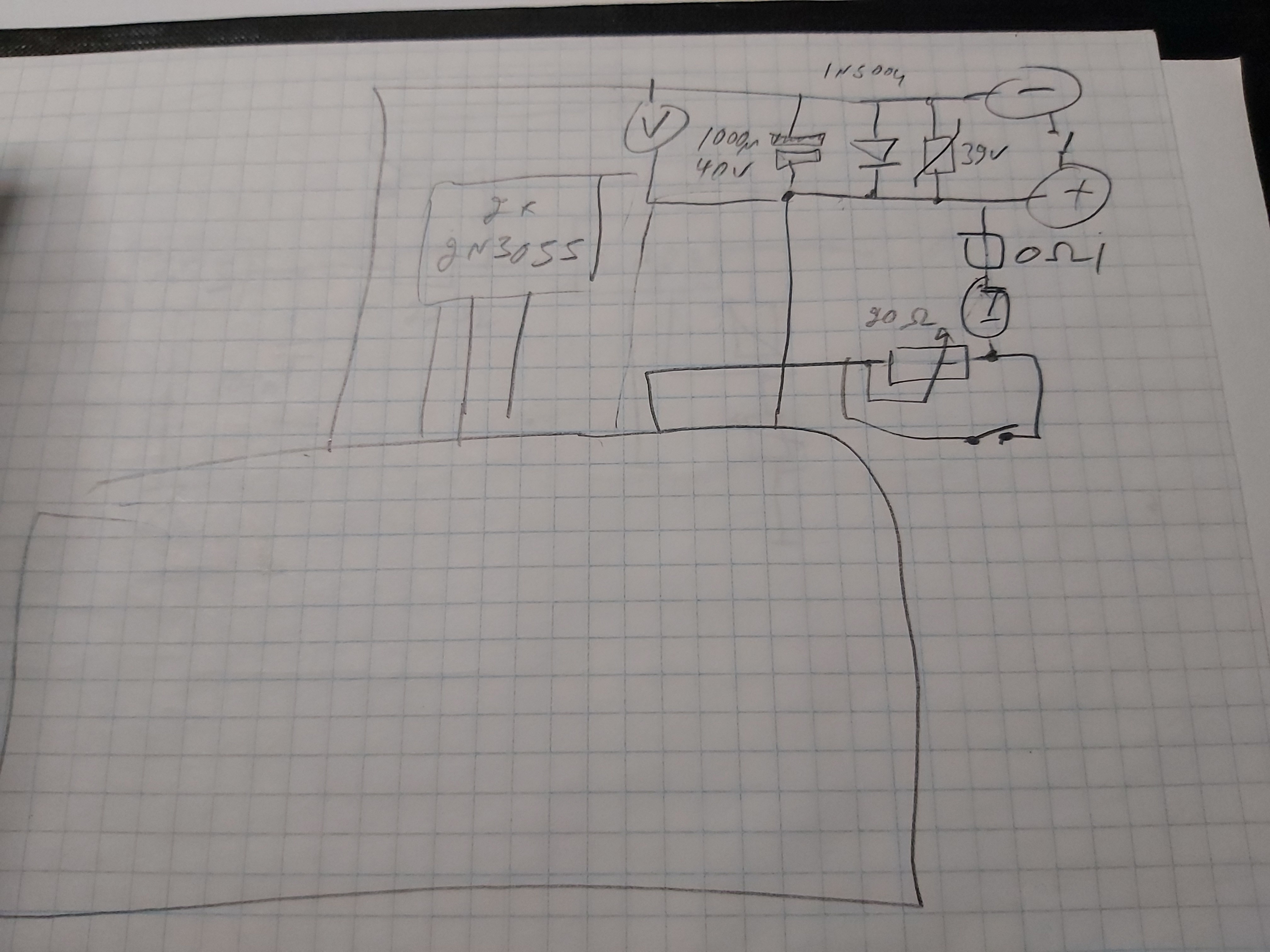
I also added some protection to the output in the form of capacitor, diode and VDR on the output. Those protections protect the electronics inside the power supply against external over voltages through the power output terminals (for example when powering inductive components like relays, solenoids and electrical motors). Here is overview of the connection of different blocks of power supply and protection. The output capacitor also guarantees very clean output voltage and that there is no danger that power supply would start to oscillate with some demanding load. The downside of the output capacitor is that there is some charge stored to capacitor, so when lowering voltage it takes some time, and if you short circuit the output, you get current spike from capacitor discharging before current limiting kicks in.
Those were the main parts of this laboratory power supply that has served me well for very many years without problems. I have used it for powering very many electronics project, electrical devices and even used it to charge batteries. Having separate voltage and current setting allows safe charging of many different types of batteries if you know what you are doing (set the voltage and current right and connect the battery the right way).
Some days ago I posted some pictures of this power supply to a Facebook electronics group and got a question: What should I use for 10 amp??
The basic circuit design as such should be able to handle more than 4A, but I intentionally limited current to that maximum with that 0.1 ohm current limiting resistor. That limits the output current to around 4.5 amperes because L200 starts to limit current when the voltage drop over that resistor reached around 0.45V. Put smaller resistor and you can get higher current out. Two 0.1 ohm resistors in parallel and you have 9 amp current limit.
The output transistors should handle more current nicely if you put enough big heat sink. Single 2N3055 has ratings
DC Collector Current 15A and Power Dissipation Pd 115W.
Theoretically one 2N3055 would have been enough for my PSU with huge heatsink, but I used two to be able to use two smaller heatsinks (was more economical and easier to fit to back of the case).
My design should be able to handle with two transistors 20A when putting out 24-30V. When outputting lower voltages it is up to total power handling. If you try to output 3V 10A with circuit getting 33V in, the transistors would need to dissipate 300W of power that is too much for them. You need at least three, preferably more to handle that amount of power loss.
And of course the mains power transformer and rectifier should be able to handle that 10A current.
1 Comment
mapquest directions says:
The sharing forum I have read, the content is very practical, it gives me a lot of useful information, I like the content of your article very well. I hope you will have many new posts to share with readers.
mapquest directions