EMC basics: I/O

EMC Basics #5: I/O as critical circuits article gives some useful tips on the EMC issues related to inputs and outputs.

Digital inputs/outputs — The key concern for digital interfaces is ESD. A secondary concern is radiated emissions. Radiated susceptibility is rare with digital I/O, although possible at very high RF levels. The solutions for both radiated problems include filtering at the interface and/or or shielding of external cables.

Analog inputs/outputs — The key concern for analog interfaces is RF. High RF levels can cause rectification in the I/O circuits causing errors and/or noise. Typical solutions include high frequency filters and/or shielding of the external cables.

Relay outputs — Since relay drivers are usually digital, the regular digital concerns apply. In addition, inductive transients from the relay coils may pose a self-compatibility problem. Snubber circuits may be needed at either the relay (best) or at the driving circuit on the boards.

Contact inputs — Since the receiving circuits are usually digital, the regular digital concerns apply.

When designing or reviewing circuit boards for EMI, ALL of the I/O circuits deserve EMI attention!

I have some additions to those suggestions:

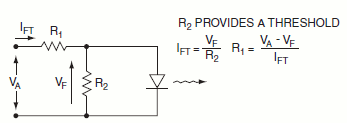
Opto-isolators (also known as optocouplers) work to protect the receiving system at the expense of the sending system needing to drive the cables/interconnects. They are a great way to isolate digital from power circuits but have limited bandwidths. Fairchild Application Note AN-3001 Optocoupler Input Drive Circuits gives some implementation tips for optocoupler based input circuits.

optocoupler

Using a balanced line interface for sensitive and/or fast signal is a very good idea. Using balanced interface reduces EMI pickup and radiated EMI considerably compared to single-ended signals. Applications like telephone lines, analogue instrumentation, professional audio signals, fast serial bus standards and Ethernet all use balanced interfaces to get good noise performance.

Be careful on the grounding of cable shield when they enter the cabinet. The cable shields should be grounded at the point where they enter the metal cabinet. This will stop the RFI from entering inside the device. This advice applies especially to sensitive analogue circuits like audio interfaces. Proper grounding is essential in keeping RFI and ground loop noise away.

In many power controlling applications you can’t beat a relay for isolation or low on-resistance, as well as low cost. For relay outputs you need to carefully consider the need for snubber circuits. When talking about snubber circuits there are two kind of applications for them: Snubber cuircuit in parallel with the relay coil and snubber circuits in parallel with the relay output.

For the relay coil driven with DC voltage at known polarity an inexpensive diode in parallel with the coil works well. If the relay is switched with AC, the DC polarity is not known or you need very fast operation (parallel diode can slow down relay release time).

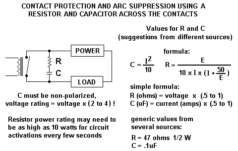
You need to consider snubber circuit also at the relay contact side especially if you are switching anything that is even slightly inductive. Relay contacts can arch. The end result of Contact Arc Phenomenon is shortened contact life. In addition to that arching causes lots of electromagnetic interference.

Relay Contact Life article tells that perhaps the most popular method of quenching an arc between separating contacts is with an R-C network placed directly across the contacts. Contact Protection and Arc Suppression Methods for Mechanical Relays gives information how to design a suitable R-C network for quenching an arc.

mechrela

Some relay users connect a diode across the inductive load to prevent counter-voltage from reaching the contacts. In some application zener diodes are used. The MOV performs in a manner similar to back-to-back zener diodes, and can be used in both AC and DC circuits.

An added benefit of arc suppression is the minimization of EMI. An unsuppressed arc between contacts is an excellent noise generator. Arc may radiate energy across a wide spectrum of frequencies. By suppressing the arc, electromagnetic interference is held to a minimum. By quenching the arc quickly, this action is held to a minimum. The result often is a considerably lessened amount of electromagnetic and radio frequency interference. Contact arc noise can be troublesome to sensitive components in a circuit. In worst-case conditions, EMI can cause unwanted turn-on of IC logic gates, SCRs, and triacs, and can cause damage to other semiconductor devices.
207 Comments

  1. Tomi Engdahl says:

    Review: Tool measures power-line EMI
    https://www.edn.com/review-tool-measures-power-line-emi/

    Ever since we’ve switched from incandescent to LED lighting and from linear to switch-mode power supplies, EMI on power lines has started to become an issue, especially for those of us who still enjoy AM broadcast radio and amateur radio in the MW and HF spectrum (0.54 to 30 MHz). Add defective power utility transmission line arcing and corona, and many amateur radio enthusiasts and military operators simply can’t receive national and international stations with the resulting hash on their receivers.

    I wrote an article in 2015, How cops are finding “grow ops” with AM radios, about how those who were growing marijuana illegally were purchasing poorly-filtered power supplies (“ballasts”) from Asia for their lighting. These power supplies were producing EMI over a wide range, up to 1 mile away, and the police in Oakland, California, realized they could hear the hash coming through their AM radios, which allowed them to zero in on these grow operations.

    Because this broadband high frequency EMI is both conducted and radiated, it’s very difficult to get rid of at this point in time; an unintended consequence of the desire for more efficient power supplies. In the meantime, those using these frequencies are suffering the consequences.

    OnFILTER recently released a power line EMI adapter that can be used with spectrum analyzers or oscilloscopes to evaluate conducted power line EMI (Figure 1). They have units that can plug directly into a wall socket or one that includes test leads.

    https://www.onfilter.com/emi-adapter-msn15

    Reply
  2. Tomi Engdahl says:

    Fields from specific power lines
    Use the links in the table to find the field for any specific power lines.
    https://www.emfs.info/sources/overhead/specific/

    Reply
  3. Tomi Engdahl says:

    “Dry” switching means that the goodie current being switched is “negligible”, that the current being interrupted and resumed is negligibly small. What constitutes negligibility may be open to debate or even to dispute

    “Wet” switching, by the obvious reasoning, means that the goodie current is substantial where that word might mean an ampere or more, perhaps a tenth of an ampere or more, perhaps 10 mA or more , but you get the idea. Again, this may be open to debate and dispute as well.

    Relays rated for wet service will have contact materials that can withstand arcing when their contacts open up or when they bounce a bit when closing.

    Source:
    https://www.edn.com/wet-and-dry-switching/

    Reply
  4. Tomi Engdahl says:

    The Difference Between Contactors And Relays – ELECTROMAGNETIC SWITCHES electricians use
    https://m.youtube.com/watch?v=YwAm2D-mm_g&feature=share

    Reply
  5. Tomi Engdahl says:

    What is the difference between ac contactor and dc contactor?

    Main differences between AC contactor and DC contactor: Iron core of AC contactor would generate eddy current and hysteresis loss, while the DC contactor has no core loss. … AC contactor adopts a grid arc extinguishing device while the DC contactor adopts a magnetic quenching arc extinguishing device
    #contactor #modularcontactor #hvac #hecheng #hechengelectrical

    Reply
  6. Tomi Engdahl says:

    How Optocouplers work – opto-isolator solid state relays phototransistor
    https://www.youtube.com/watch?v=3AVHqV_xASQ

    Reply
  7. Tomi Engdahl says:

    Low noise solid state relays suitable for use in professional food equipment and commercial, industrial, and home appliances
    https://www.arrow.com/en/research-and-events/articles/sensata-crydom-low-noise-solid-state-relays

    Reply
  8. Tomi Engdahl says:

    Directional Control Valve Working Animation | 5/2 Solenoid Valve | Pneumatic Valve Symbols Explained
    https://www.youtube.com/watch?v=bXXL-0sf8gs

    But this video is about different types of control valves known as Directional Control Valves or DCVs for short. You may hear of them as solenoid valves or spool valves as well.

    The control valves are mostly known for their adjustability and throttling capabilities. But the valves we’re going to talk about them are the types that control the “direction” of the liquid flowing inside the pipe. Directional control valves are used in pneumatic and hydraulic flow control systems.

    So there are pneumatic directional control valves and hydraulic directional control valves. Sometimes the hydraulic directional control valves are called spool valves.

    In this video, you’ll learn how a directional control valve works and how you should read and interpret its symbols. And all of these by a real-world application example of a 5/2 solenoid valve in pneumatic systems.

    Reply
  9. Tomi Engdahl says:

    Why RELAYs go BOOM!!! And How to Use Them
    https://www.youtube.com/watch?v=PHcCSZ5nScM

    You think you know how relays work until one blows in your face!!

    Reply
  10. Tomi Engdahl says:

    The spike that causes the problem to control electronics could be caused by the pneumatic solenoid coils that relays are controlling. Switching off solenoid can cause quite nasty spark inside relay between contacts. To avoid this problem a snubber circuit is recommended to be used across relay contact and/or the solenoid itself. That snubber could be capacitor, RC circuit, VDR, zener diode or diode depending on the other properties of application.

    Reply
  11. Tomi Engdahl says:

    Please read and follow these important guidelines:
    •Use separate paths to route wiring for power and devices. If powerwiring and device wiring paths must cross, make sure the wires are perpendicular at the intersection point.NOTE: Do not run signal or communications wiring, and power wiring through the same wire conduit. To avoid interference, wires with different signal characteristics should be routed separately.
    •Use the type of signal transmitted through a wire to determine which wires should be kept separate. The rule of thumb is that wiring that shares similar electrical characteristics can be bundled together.

    From Moxa manual
    https://cdn-cms.azureedge.net/getmedia/713d2ab3-8758-4340-9b3c-935c67195603/moxa-eds-505a-eds-508a-series-qig-v11.1.pdf

    Reply
  12. Tomi Engdahl says:

    Directional Control Valve Working Animation | 5/2 Solenoid Valve | Pneumatic Valve Symbols Explained
    https://www.youtube.com/watch?v=bXXL-0sf8gs

    What is a Directional Control Valve?
    https://upmation.com/directional-control-valve/

    Reply
  13. Tomi Engdahl says:

    Effect of the Cable Capacitance
    of Long Control Cables on
    the Actuation of Contactors
    http://www.moeller.net/binary/ver_techpapers/ver949en.pdf

    The contactor is the most important switching device in industrial and commercial applications. Its importance has
    further increased due to the influence of automation. This has given rise to some significant advancements in the
    development of contactors, of which the user is often not aware. For example, the power required for switching has
    been considerably reduced in recent years due to the use of integrated actuation electronics.

    1. Cable capacitances
    In certain circumstances, long control
    cables in AC actuated control circuits
    may prevent the disconnection of contactors due to the cable capacitance present.
    Even if the command contacts are open,
    the coil current can still flow due to the
    cable capacitance so that the contactor
    remains in the On position if sufficient
    sealing current is present.
    The effect of cable capacitance depends
    on the design of the control current circuit:

    1.1 Capacitance of control cables
    A guide value for control cable capacitances between two conduc tors is
    approx. 0.3µF per km for two-wire control, and approx. 0.6µF per km between
    three conductors for three-wire control.
    The following equation should be used:
    CL = 0.3 (µF/km) x l (km)
    Two-wire control (1.3)
    CL = 0.6 (µF/km) x l (km)
    Three-wire control (1.4)

    Reply
  14. Tomi Engdahl says:

    120/240V to logic level optoisolator (with schematic)
    https://www.youtube.com/watch?v=0C2o0rXOXYE

    Reply
  15. Tomi Engdahl says:

    How Optocouplers work – opto-isolator solid state relays phototransistor
    https://www.youtube.com/watch?v=3AVHqV_xASQ

    Optocoupler. In this video we learn how optocouplers work and also look at some simple electron circuits you can make yourself to understand how an optocoupler, opto-isolator, phototransistor, photocoupler works.

    Reply
  16. Tomi Engdahl says:

    Why DC contactor and AC contactor cannot be replaceable to each other
    http://www.dycontactor.com/en/display.asp?id=777

    The AC contactor has a small number of turns in the structure, and the number of turns of the DC contactor is large. We can distinguish from the volume of the coil when the current of the main circuit is too big (Ie>250A). The reactances of DC contactor coil is large and thus the current is small. If you are connecting DC contactor to AC power, it will not work because of the small current. But the coil of the AC contactor has a small reactance and the current is too large for it. If connect AC contactor to DC power, the current will be unbearable for the coil. In another word, AC contactors used in DC circuits will burn by large currents. And DC contactors used in AC circuits will not work because of the small current.

    The coil of AC contactor is an inductor. The inductance of the inductor is proportional to the frequency. So AC contactors and DC contactors cannot be replaceable to each other. If we put the AC contactor in the DC circuit, it will burn out because of the excessive current.

    If we put DC contactor in AC circuit, the DC contactor will not work because of the AC inductive reactance. There is fewer coil turns, higher impedance, lower current, and more noise in AC contactor.

    As there is a coil in AC contactor in an AC circuit, the contactor shows an impedance under the action of the AC. That is, not only the coil resistance exists, but also the reactance exists. Although the resistance value of the coil is small, the coil reactance is large. So the operating current will not exceed the rated current, and the contactor can work. If the AC contactor is in a DC circuit, the resistance of the coil is 0. The resistance is small (self-resistance). The operating current may exceed its rated current. And the coil wire is thin, resulting in the coil damage. Also, DC arc and AC arc are different in nature. AC arc has a zero-crossing value, DC arc is not easy to extinguish. Thus the contacts of the contactor and the arc extinguishing device have to be different. If the AC contactor is in DC circuit, the contacts are liable to stick or burn

    The difference between AC contactors and DC contactors
    https://www.geya.net/2021/04/15/the-difference-between-ac-contactors-and-dc-contactors/

    AC Contactors and DC Contactors

    The iron core of the AC contactor produces eddy current loss and hysteresis loss. Laminating the iron core with silicon steel plates reduces the eddy current and hysteresis loss by alternating the iron core’s magnetic field to prevent overheating the iron core. Therefore, the iron core of the AC contactor is usually E-shaped. When an alternating current passes through the electromagnetic coil, the coil generates an alternating driving force on the armature. When the alternating current is zero, the coil’s magnetic current and the actuation force on the armature are both in zero states. In the reset action of the spring, the armature will exhibit chemotactic release potential. This makes the actuation force between the moving and static iron cores change with alternating current changes, resulting in changes and noise, thereby accelerating the contact wear between the moving and stationary iron cores, resulting in poor contact. In more severe cases, it may also cause burnout of the contacts. A copper ring, known as a short-circuit ring, is inserted into the end of the stem to eliminate contact burnout. This short-circuit loop is equivalent to the secondary winding of the transformer.

    When the coil is connected to an AC power source, the coil will generate a magnetic current and the induced current in the short-circuit loop. At this time, the short-circuit loop is equivalent to a purely inductive circuit. According to the purely inductive circuit phase, we know that the magnetic flux caused by the coil current and the magnetic flux generated by the short-circuit loop’s induced current cannot be simultaneously zero. When the current provided by the power supply is zero, the induced current of the short-circuit ring cannot be zero. Its magnetic current attracts the armature pair, thereby overcoming the armature’s release trend and ensuring that the armature is always actuated when it is turned on. As a result, noise and vibration have been significantly reduced, so the short-circuit ring is also called a vibration elimination ring.

    The iron core in the DC contactor coil does not generate eddy currents, and there is no heat generation problem in the DC iron core so that the iron core can be made of complete cast steel or cast iron, usually U-shaped.

    The coil of an AC contactor has few turns and low resistance, but the coil also generates heat, so the coil is usually made into a thicker short cylindrical shape. While avoiding the burning of the coil, there is a gap to facilitate heat dissipation. The coil of the DC circuit has no inductance, so the coil has more turns, which leads to more significant resistance and copper loss. The coil is usually made into a thin and cylindrical shape to maintain the coil’s good heat dissipation.

    AC contactor uses grid arc extinguishing device; DC contactor uses magnetic arc extinguishing device.

    The AC contactor’s starting current is vast, and its maximum operating frequency is about 600 times per hour. In comparison, the maximum operating frequency of the DC contactor is 1200 times per hour.

    In emergencies, AC contactors can be used instead of AC contactors. However, the action time cannot exceed 2 hours (because the AC coils’ heat dissipation performance is worse than that of DC coils, depending on their structure). If you need to use it for a long time, it is best to connect a resistor with the AC coil series. On the contrary, the DC contactor cannot be replaced by an AC contactor.

    Reply
  17. Tomi Engdahl says:

    https://electronics.stackexchange.com/questions/163799/what-is-switch-contact-rating

    The max current that won’t over-heat the contacts; the max voltage that won’t burn them by arcing during break.

    The contact rating is the voltage/current that the switch can repeatedly connect and interrupt without degrading it’s design life-cycle operation count.

    Take the ratings as the maximum safe operational ratings of a switch. Yes, a 240VAC 5A rated switch will operate just fine on 127 VAC, but up to 5 Amps.

    The DC rating is almost always lower because of the ability of switch to quench the arc when opening a DC circuit.

    Reply
  18. Tomi Engdahl says:

    https://www.powerelectronics.com/content/article/21854186/demystify-current-ratings-for-connector-selection

    Contact Current Rating

    By one common definition, a power connector contact is any contact used at or near its rated current capacity. Thus, a signal contact rated at 2A is actually a power contact when it delivers power from the module to a p.c. board.

    Separable connector contacts generally consist of a male pin mated with a receptacle that contains one or more spring contact “fingers.” The current carrying capacity of a connector’s mated contact pair depends mainly on:

    Contact material.
    Geometry.
    Spring force between the pin and receptacle contacts.

    Reply
  19. Tomi Engdahl says:

    https://www.carlingtech.com/amp-hp-volts

    Types of Loads

    An electric load is the amount of electric power delivered or required at any specific point or points on a system. The requirement originates at the energy consuming equipment of the consumers. More simply put, a load is the piece of equipment you turn on and off.

    Resistive loads primarily offer resistance to the flow of current. Examples of resistive loads include electric heaters, ranges, ovens, toasters, and irons. If the device is supposed to get hot and doesn’t move, it’s most likely a resistive load.

    Inductive loads are usually devices that move and normally include electric magnets, like an electric motor. Examples of inductive loads include such things as power drills, electric mixers, fans, sewing machines, and vacuum cleaners. Transformers also produce inductive loads.

    High Inrush loads draw a higher amount of current or amperage when first turned on, compared to the amount of current required to continue running. An example of a high inrush load is a light bulb, which may draw 20 or more times its normal operating current when first turned on. This is often referred to as lamp load. Other examples of loads that have high inrush are switching power supplies (capacitive load) and motors (inductive load).

    UL/CSA Ratings

    Typical UL/CSA amperage rating is a single value which represents inductive/resistive loads. If a horsepower rating is listed, it indicates the switch is appropriate for use on motor loads that are rated at the given horsepower. If there is no horsepower rating listed, switches are tested to an inductive/non-horsepower load at 75% of the power factor.

    A typical example of a UL/CSA Rating is listed below:
    10A 250VAC
    15A 125VAC
    3/4HP 125-250VAC

    European Ratings

    The typical European rating will distinguish between resistive and inductive load ratings. Below is an example of a typical European rating:
    16(4)A 250V ~ T85 µ

    In this example the 16 = resistive load amperage; (4) = inductive load amperage; A= amperage; 250V= voltage; ~ = AC; T85= Maximum operating temperature in centigrade; µ = micro-gap (<3mm) approved.

    If there is less than 3mm of air space between a switch's contacts in the open position, a micro-gap approval (µ) may be granted. This mark indicates that the switch has general application approval with a qualifier that another device, such as a cord and plug, must provide an alternate means of disconnection from the main power source.

    L & T Ratings

    An "L" rating denotes the ability of a switch to handle the initial high inrush characteristics of a Tungsten Filament Lamp on AC voltage only. A "T" rating is the equivalent lamp load for DC.

    H Rating

    An "H" rating denotes a non-inductive resistive rating.

    Illuminated Switch Ratings

    For illuminated switches with dependent lamps, line voltage should match the lamp voltage rating.

    Operating Temperature

    All European certified switches have a maximum operating temperature of 85 degrees Centigrade, unless otherwise noted. Switches rated T85, if directly operated, should not be used in applications where the temperature of the actuating member inclusive of any temperature rise exceeds 85 degrees Centigrade.

    Unless otherwise noted, all North American rated switches have a maximum material temperature rating of 105 degrees Centigrade.

    Reply
  20. Tomi Engdahl says:

    Choosing a Proper Relay Amperage
    How to calculate for the Correct Relay
    https://relaypros.com/choosing_proper_amperage.htm

    Relay Ratings and Limits
    Relays often have two ratings: AC and DC. These rating indicate how much power can be switched through the relays. This does not necessarily tell you what the limits of the relay are. For instance, a 5 Amp relay rated at 125VAC can also switch 2.5 Amps at 250VAC. Similarly, a 5 Amp relay rated at 24VDC can switch 2.5 Amps at 48VDC, or even 10 Amps at 12VDC.

    Resistive and Inductive Loads
    Relays are often rated for switching resistive loads. Inductive loads can be very hard on the contacts of a relay. A resistive load is a device that stays electrically quiet when powered up, such as an incandescent light bulb. An inductive load typically has a violent startup voltage or amperage requirement, such as a motor or a transformer.
    Startup and Runtime Loads
    Inductive loads typically require 2-3 times the runtime voltage or amperage when power is first applied to the device. For instance, a motor rate at 5 Amps, 125 VAC will often require 10-15 amps just to get the shaft of the motor in motion. Once in motion, the the motor may consume no more than 5 amps. When driving these types of loads, choose a relay that exceeds the initial requirement of the motor. In this case, a 20-30 Amp relay should be used for best relay life.

    Induction Suppression Capacitors
    Controlling inductive loads requires the use of induction suppression capacitors. The purpose of this capacitor is to absorb the high voltages generated by inductive loads, blocking them from the contacts of the relay. Without this capacitor, the lifespan of the relay will be greatly reduced. Induction can be so severe that it electrically interferes with the microprocessor of the board possibly requiring the board to be power cycled.

    Reply
  21. Tomi Engdahl says:

    https://www.pickeringtest.com/en-fi/kb/hardware-topics/relay-reliability/switching-and-relay-specifications

    Understand Relay Specifications to Get the Most Out of Your Switching System

    Relay specifications aren’t simply numbers on a data sheet-you need to take them seriously. Operating a relay used outside of its specifications can severely shorten its life and cause switching system failures and even potentially damage the UUT (Unit Under Test). With that in mind, let’s look at some common relay specifications and the impact they have on switching systems.

    Life Expectancy

    Relays have moving parts and operating them causes wear and stress that will eventually lead to relay failure. The life expectancy specification provides information on when you can expect relays to mechanically wear out. Essentially, this specification is the number of times a relay can operate under no load or light load conditions where contact wear, relay temperature and forces acting on the moving parts are simply the result of mechanical activation.

    There are two types of mechanical relays: reed relays and electromechanical relays (EMRs). In general, instrument grade reed relays have the longest mechanical life because the relay has few moving parts. The reed relay blade bends rather than being moved on a pivot point, and the contact is contained in a hermetically sealed glass envelope, so it is less susceptible to contaminants and mechanical defects.

    EMRs tend to have a shorter mechanical life than reed relays, but they have greater power handling capacity.

    The maximum switching voltage of a relay is the maximum voltage that can be across the contacts whether the relay is open or closed. Operating a relay with high voltages present can cause arcing, and this in turn erodes the contacts and eventually degrades contact performance.

    It is also important to remember that the maximum switching voltage of a switching system may be less than the maximum switching voltage of the relays because relay specifications are usually defined using resistive loads. Because switching systems have some amount of capacitance (the largest contributor to this is the capacitance between traces on the PCB), the maximum switching voltage system specification may be lower than the relay specification.

    Cold Switching Voltage

    Relays may be able to sustain higher voltages across their contacts than the maximum switching voltage, provided no attempt is made to operate the relay while the signal is applied. This specification is called the cold switching voltage or standoff voltage.

    Relays with high standoff voltages can be useful in insulation testing, but the user MUST avoid switching the relay while the voltage is applied since it exceeds the contact voltage rating when being operated.

    When a switching system has a cold switching voltage specification, this means that the spacing between the PCB traces have been designed to withstand this voltage.
    Switch Current

    When a relay is hot switched, the switch current is the maximum current that the relay can sustain when being opened or closed and not sustain contact damage.
    Carry Current

    If a relay’s contacts are already closed, the relay may be able to sustain a higher current than the switch current. This is called the carry current. The carry current is normally limited by contact resistance, which causes the contacts to heat up. When a relay is carrying a current greater than the switch current, the relay must not be opened until the current is reduced.
    Pulsed Carry Current

    Some relays or switching systems may have a pulsed carry current specification. A pulsed carry current simply heats the relay contacts, it does not create the same arcs that hot switching creates.

    Power Rating

    Some users ignore the power rating, but this specification has a major impact on relay life. A signal at both the maximum switching voltage and the maximum switch current will generally exceed the power rating of the relay.

    For example, a relay with a 60W power rating, may have a maximum switching voltage of 250V and a maximum switch current of 2A. A 250V, 2A signal has a power of 500W, which exceeds the power rating of the relay by nearly an order of magnitude. To stay within the power rating, a signal with a maximum voltage of 250V, should have a current of no more than 240mA.

    Most relays, therefore, have a complex useful working area. The higher the switched voltage, the lower the maximum switch current must be for a relay to handle it safely.

    In addition, at high DC voltages, the power rating for a mechanical relay is lower than the rating at lower voltages because the closing or opening of the relay creates an arc that in turn creates a plasma which can damage the contacts and relay materials. Users should always check the load curves provided on a relay’s data sheet when DC signals are being switched above 30V.

    Minimum Switching Voltage

    Some types of relay have a minimum switching voltage that must be present for the relay to switch reliably. This is especially true for relays used to hot switch signals where contact wear can occur and expose the underlying materials. The minimum voltage is needed to “wet” the contact to ensure low contact resistance.

    Reed relays are particularly effective for low voltage switching because their contacts are hermetically sealed in glass, and contaminating films cannot build up on the contacts. Some relays designed for telecommunications applications also have minimum voltage ratings because they have gold contacts. High power relays often require higher minimum voltages than low power relays once the protective gold flash has been eroded either by hot switching or mechanical wear of their high-pressure contacts.

    Operate Time

    The operate time specification can sometimes be confusing to users, but can be critical in precise timing situations. An application not taking into account relay closure times may mean that a particular measurement may not be captured correctly because the relay was not yet closed and carrying the signal.

    Reply
  22. Tomi Engdahl says:

    General Applications of Electrical Relays
    https://components.omron.com/relay-basics/general-app

    Coil Specification

    For actual use, be sure to not exceed the coil rating; it can lead not only to performance loss but also to burn out the coil caused by overvoltage etc. Be sure to carefully select the AC coil specification by checking the applicable power source of each relay (rated voltage, rated frequency).

    Certain types of relays may not tolerate under specific rated voltage and rated frequency.
    If used under such condition, it can cause abnormal heating and malfunction.

    Contact Specification

    Contact ratings are the standard values for guaranteed relay performance and generally indicates the current rating of the relay contacts.
    The rating varies depending on the voltage applied and the types of electrical loads. In other words, the rating includes the specification of the maximum voltage applied to the relay contacts and the maximum current that can be passed to control the electrical load.

    Inrush Current and Ratings

    The TV rating is one of the representative ratings approved by UL and CSA regulations to evaluate the inrush current withstand capability. The rating indicates the level of relay’s capability to switch the load, including the inrush current.

    For example, relays for television power supplies need to obtain the TV rating.
    TThe switching test (durability test) of these relays is performed using a tungsten lamp as a load and must withstand in total 25,000 times of the durability test.

    DC Circuits

    Arc is an electric spark that occurs between the contacts when the relay closes the electric circuit.
    As the voltage and current amplitude increase, the arc rises. When the switch is closed slowly, it takes longer time for an arc to form. This can cause the contacts to wear out quickly.

    In alternating current (AC), which constantly changes its direction of flow, the arc is quenched every time an overvoltage is delivered.
    On the other hand, indirect current (DC) only flows in one direction, which allows forming an arc to take longer, leading to quicker contact wear out and durability decrease.

    Also, a transition phenomenon of the contact occurs, which can cause irregularities at the contact points, which can cause malfunctions that can not be separated because they are caught.

    Minimum load application of electrical relays

    A relay may face a problem of contact resistance build-up when switching minimum load applications. Whenever there is a rise in contact resistance, contacts would normally recover by the subsequent operation. Contact resistance may also increase, caused by film formation.

    To determine if the measured contact resistance value predicts a relay failure shall depend on whether it is causing a circuit problem or not.
    For this reason, only default values are specified as standard failure rates of relay contact resistance. Failure rates (*) are expressed as P level (reference value) as one indicator for minimum applicable loads.

    Using Relays with a Minimum Load Application

    When selecting a suitable relay to switch a minimum load application, be sure to consider the type of load you are switching as well as the required contact material and the contact arrangement.

    The contact reliability when controlling minute loads greatly depends on the contact material and contact arrangement.
    For example, twin contact points are more reliable than single contact point for minimum load applications simply from the reason that redundancy in parallel operation of twin contact provides greater reliability than is offered by single contact.

    Electrical relay durability & life cycle

    Durability (life) of a relay is the number of times the relay can switch until it fails to meet the specified values in terms of operating characteristic and performance.
    Relay durability is divided into two categories: Mechanical Durability (relay life) and Electrical Durability (relay life).

    Mechanical durability (relay life)
    This is to see how many cycles the relay can operate at the specified switching frequency with no load applied to the contacts.

    Electrical durability (relay life)
    This is to see how many cycles the relay can operate at the specified switching frequency with the rated load applied to the contacts.

    Reply
  23. Tomi Engdahl says:

    EEVblog 1409 – The DANGERS of Inductor Back EMF
    https://www.youtube.com/watch?v=hReCPMIcLHg

    A practical demonstration of Lenz’s law and back EMF in an inductive relay coil and how to solve it using a Freewheeling/Flywheel/Flyback/Snubber/Clamp diode. Also the downsides of clamping diodes, and switch arcing supression.
    Also a look at an AMAZING potential phenomenon you probably haven’t seen before!
    Actually, two rather cool things you probably haven’t seen before.
    Along with transistor ratings, transistor storage current, and Collector-Emitter breakdown voltage, there is a lot to unpack in this video.

    00:00 – Recap of Relays, Inductors, Faraday & Lenz’s Laws
    02:30 – Relay Back EMF Explained
    07:09 – The Flywheel analogy of Inductors
    08:30 – Relay circuit demonstration
    12:35 – 700V Back EMF!
    14:43 – BJT Transistor Storage Time
    17:03 – Back EMF Diode clamp demonstrated
    19:06 – An AMAZING demonstration!
    24:43 – Trap for young players
    25:23 – DOWNSIDES of Back EMF Diodes
    28:38 – BONUS cool effect of Back EMF diode DEMONSTRATED

    EEVblog 1406 – DC Circuit Transients Fundamentals
    https://www.youtube.com/watch?v=8nyNamrWcyE&t=0s

    Reply
  24. Tomi Engdahl says:

    Inductive spiking, and how to fix it!
    https://www.youtube.com/watch?v=LXGtE3X2k7Y

    A description of inductive spiking, why it happens, and how a diode can save your circuits. Make sure you enable annotations as there is an error in one of the diagrams.

    Reply
  25. Tomi Engdahl says:

    Auto-Qualified Optoisolator Offers 200-V Collector-Emitter Rating
    Dec. 27, 2021
    Optocoupler meets automotive standards—the device squeezes 3750-V isolation into a tiny 4-pin SO6 package.
    https://www.electronicdesign.com/markets/automotive/article/21212721/electronic-design-autoqualified-optoisolator-offers-200v-collectoremitter-rating?utm_source=EG%20ED%20Analog%20%26%20Power%20Source&utm_medium=email&utm_campaign=CPS211220033&o_eid=7211D2691390C9R&rdx.ident%5Bpull%5D=omeda%7C7211D2691390C9R&oly_enc_id=7211D2691390C9R

    Optoisolators (also known as optocouplers or photocouplers) don’t radiate a lot of component glamour, but they are critical interface components in many systems. They offer multiple problem-solving uses, including “breaking” ground loops and providing galvanic (ohmic) isolation between a system’s functional blocks.

    Such attributes are needed in arrangements where high common-mode voltages affect system connectivity, or when a component failure could put unacceptable high voltage onto low-voltage circuits or even endanger users. These functionally simple, diminutive components offer a high level of isolation—typically several thousand volts—in a tiny package, as clearly demonstrated by various standardized tests. Among other key specifications is the collector-emitter voltage (VCEO), a parameter that derives from their underlying transistor-like structure and nomenclature.

    Recognizing this, the TLX9188 infrared optoisolator from Toshiba Electronic Devices & Storage Corp. supports a collector-emitter voltage up to 200 V (minimum) (see figure). This is the highest VCEO value Toshiba offers in an automotive optocoupler and 2.5X higher than its existing optocoupler, the TLX9185A.

    The device offers a current transfer ratio (IC/IF) from 50% (minimum) to 600% (maximum).

    Note that even if you don’t have an immediate need for this type of component, Toshiba has a very informative, highly readable 20-page application note “Safety Standards for Photocouplers.” This note explains frequently used terminology along with examples from component and equipment safety standards for photocoupler products. Given the depth, intensity, and sheer volume of these regulatory standards and mandates, any insight in this area is appreciated.

    https://toshiba.semicon-storage.com/info/docget.jsp?did=61477&prodName=TLX9188

    Reply
  26. Tomi Engdahl says:

    Mitigate EMI to Keep Railway Safety on Track
    Jan. 19, 2022
    Today’s railway systems demand higher power motors and associated equipment, which are main perpetrators of EMI. That interference can in turn take a toll on railway signaling systems.
    https://www.electronicdesign.com/power-management/whitepaper/21214429/electronic-design-mitigate-emi-to-keep-railway-safety-on-track?utm_source=EG%20ED%20Analog%20%26%20Power%20Source&utm_medium=email&utm_campaign=CPS220111029&o_eid=7211D2691390C9R&rdx.ident%5Bpull%5D=omeda%7C7211D2691390C9R&oly_enc_id=7211D2691390C9R

    Reply
  27. Tomi Engdahl says:

    Mitigate EMI to Keep Railway Safety on Track
    Jan. 19, 2022
    Today’s railway systems demand higher power motors and associated equipment, which are main perpetrators of EMI. That interference can in turn take a toll on railway signaling systems.
    https://www.electronicdesign.com/power-management/whitepaper/21214429/electronic-design-mitigate-emi-to-keep-railway-safety-on-track?utm_source=EG%20ED%20Auto%20Electronics&utm_medium=email&utm_campaign=CPS220127050&o_eid=7211D2691390C9R&rdx.ident%5Bpull%5D=omeda%7C7211D2691390C9R&oly_enc_id=7211D2691390C9R

    Reply
  28. Tomi Engdahl says:

    This Week in PowerBites: Spotlight on Optocouplers
    Feb. 4, 2022
    The optocoupler continues to evolve to meet increasingly stringent requirements emerging from power-conversion apps, where safety is a top design driver. This week’s PowerBites focuses on some recent developments in optocouplers—and their alternatives.
    https://www.electronicdesign.com/power-management/whitepaper/21216066/electronic-design-this-week-in-powerbites-spotlight-on-optocouplers?utm_source=EG%20ED%20Analog%20%26%20Power%20Source&utm_medium=email&utm_campaign=CPS220127064&o_eid=7211D2691390C9R&rdx.ident%5Bpull%5D=omeda%7C7211D2691390C9R&oly_enc_id=7211D2691390C9R

    Simple, (mostly) reliable, and based on decades-old technologies, we often take the optocoupler for granted, despite the vital roles it plays in many power applications. But we ignore these devices at our own peril since they continue to evolve to meet the tougher requirements—particularly in terms of safety—emerging from advanced battery systems, motor drives, and other power-conversion systems.

    Since these indispensable workhorses sometimes get overlooked in favor of more glamorous power technologies, we’re devoting this issue of PowerBites to some recent developments in optocouplers—and their alternatives.

    Reply
  29. Tomi Engdahl says:

    Hiljattain oli juttua CE-merkinnästä ja sen vaatimuksista. Ottamatta kantaa tarkkoihin EMC-standardeihin ja niiden vaatimuksiin, täältä löytyy hyvää juttua siitä mitä EMC-testejä on ja miten ne tehdään. https://emcfastpass.com/

    https://emcfastpass.com/emc-testing-beginners-guide/

    Reply
  30. Tomi Engdahl says:

    Paras neuvo, mitä olen ikinä nähnyt pienille firmoille, jotka joutuvat ostamaan EMC-testauspalvelut ulkoa, on hankkia oma ESD-pyssy. Siinä vaiheessa kun on saanut oman tekeleensä kestämään ja sietämään standardin mukaiset “ampumiset”, on jo korjannut monta ongelmaa, jotka olisivat tulleet emissio- ja immuniteettitesteissä vastaan.

    Reply
  31. Tomi Engdahl says:

    The Importance of EMI and EMC Testing
    https://www.astrodynetdi.com/blog/the-importance-of-emi-and-emc-testing

    Electromagnetic emissions can affect the functioning of electronic devices, electrical systems, and radio frequency (RF) systems. Since the electricity in a circuit is never entirely contained, all electronic devices emit some level of electromagnetic radiation. This means any device could potentially generate disruptive electromagnetic fields and may be vulnerable to the emissions of other electronics and electrical systems.

    Before a final product is brought to market, the manufacturer must prove its compliance with Electromagnetic Interference (EMI) and Electromagnetic Compatibility (EMC) testing requirements. The testing helps ensure that new products under development can function as intended when used alongside current devices and systems in their shared operating environment. So, what is EMI and EMC in regards to the regulatory testing of electronic components and equipment?

    Reply
  32. Tomi Engdahl says:

    Engineers Ignore EMI, EMC, and Noise at Their Own Risk
    Aug. 6, 2021
    Failure to address electronic interference in the early stages of a device’s development can lead to prolonged delays down the road that cost both time and money—or create safety risks in the case of electronics in cars or on factory floors.
    https://www.electronicdesign.com/technologies/analog/whitepaper/21171246/electronic-design-engineers-ignore-emi-emc-and-noise-at-their-own-risk?utm_source=EG+ED+Analog+%26+Power+Source&utm_medium=email&utm_campaign=CPS220415033&o_eid=7211D2691390C9R&rdx.ident%5Bpull%5D=omeda%7C7211D2691390C9R&oly_enc_id=7211D2691390C9R

    Nearly all electronic hardware creates electromagnetic interference (EMI), which at times can be a plague on the performance of other devices in the surrounding area or even cause malfunctions. Electronics engineers also often need to guarantee their designs do not create noise that can affect other devices, inadvertenly telling them to do something they shouldn’t—a property also called electromagnetic compatibility (EMC).

    Failure to address electronic interference in the early stages of a device’s development can lead to prolonged delays down the road that cost both time and money or create safety hazards. Most electronic devices need to withstand a degree of EMI, whether to meet industry standards—in the case of aerospace and defense or factory machinery—or tight regulatory requirements—in the case of auto electronics or medical equipment.

    To reduce EMI in a design, electronics engineers first need to understand where it comes from (coupled from cables or physical conductors? Radio transmissions or stray magnetic fields? Other sources?) and how it may affect the device. But even after assessing the situation, engineers are usually left with more questions than answers when it comes to mitigating EMI and noise. What should I do to improve my design? What types of enclosures should I use? What components do I want to evaluate? Filters? Common-mode chokes?

    This article series covers a wide range of topics that can keep you ahead of the game when it comes to EMI challenges.

    Reply
  33. Tomi Engdahl says:

    What’s the Difference Between CMOS Switches and Solid-State Relays?
    June 30, 2022
    This article explores how to effectively compare the performance of CMOS switches with solid-state relays.
    https://www.electronicdesign.com/power-management/whitepaper/21245627/analog-devices-whats-the-difference-between-cmos-switches-and-solidstate-relays?utm_source=EG+ED+Analog+%26+Power+Source&utm_medium=email&utm_campaign=CPS220622018&o_eid=7211D2691390C9R&rdx.ident%5Bpull%5D=omeda%7C7211D2691390C9R&oly_enc_id=7211D2691390C9R

    This article will discuss how to derive CDS(OFF) from off isolation and how this can be used to compare the performance of solid-state relays and CMOS switches more effectively. This is important as CMOS switches are a fit for many applications where solid-state relays are used, such as switching dc and high-speed ac signals.

    Reply
  34. Tomi Engdahl says:

    Common mistakes while using the TVS diodes
    https://embeddeddesignblog.blogspot.com/2022/07/common-mistakes-while-using-tvs-diodes.html

    There are several sections in the electronics designs which play a crucial role in the functionality of the circuit. Along with functionality there is also a need protect our circuits against external noise. One of the common issue seen is the damage to the electrical circuit with the ESD and Electrical Transients. These enter the circuit at the points like the connectors where the system tries to communicate to the external world. So, protection mechanism employed at the input of the connector is very important. Protection against ESD/Transients can be achieved by TVS diode which is a kind of Zener diode.

    The protection must always be included in such a way that it should not interfere with the normal functionality of the board. The need is to protect when ESD/EFT event occurs, have a least leakage when there is no ESD/EFT. Leakage can be minimized but cannot be avoided.

    Reply
  35. Tomi Engdahl says:

    NEC Class 2 Power Circuits and Power Supplies
    https://escventura.com/manuals/sola_introNECclass2_rg.pdf

    The NEC (National Electrical Code) is a North American standard, which can be regarded as a law in most
    of the North American states. Among others, the NEC describes the installation of electric con ductors and
    equipment within or on buildings.
    The NEC also is the source of the Class 2 circuit definition, which limits the max. voltage and current. Such
    Class 2 circuits have reduced requirements regarding wire size, derating factors, overcurrent protec tion,
    insulation, wiring methods and installation materials. Considering Class 2 in a system can be an important
    factor for reducing the cost and improving the flexibility of the system. Especially when the voltage level of
    the control circuits is shifted from AC 120V to a DC voltage with 24V, Class 2 could be applicable.

    Only the lo ad side of a power supply with a nameplate rating of less than 100VA (or 5 times Vout if output
    voltage is lower than 20V) can meet the class 2 circuit requirements.
    Such Class 2 circuits have reduced requirements regarding insulation, wire size, derating factors,
    overcurrent protection, wiring methods and installation materials.

    A short installation guideline for Class 2 circuits follows:
    - Class 2 requires dry indoor use
    - Only for non hazardous location areas
    - Circuits shall be grounded
    - Two or more Class 2 circuits are permitted within the same cable, enclosure or raceway
    - Separate Class 2 circuits from other circuits

    Class 2 considers safety from a fire initiation standpoint and provides acceptable protection from electric
    shock.
    Class 3 considers safety only from a fire initiation standpoint. The output voltage can reach values up to
    100Vdc on a 100VA power level,

    The maximum power source nameplate rating for a Class 2 power supply is 100W (or 5 times Vout if the
    output voltage is in the range from 0 to 20Vdc). Similar requirements exist for the maximum nameplate
    rating of the output current: 5A for output voltages up to 20Vdc or 100 divided by Vout for voltages above
    20Vdc.

    Other Definitions with a Tendency to Confuse
    UL 508 chapter 32.7 “Limited energy circuits”:
    Has nothing to do with NEC Class 2. Requirement on power sources are less strict compared to the NEC.
    Volt-ampere capacity is limited to 200VA; voltage is limited to 100Vac.
    UL 60950 (UL 1950) or IEC 60950 chapter 2.5 “Limited power source”
    Can be one option to achieve NEC Class 2. The requirements are tougher than NEC. The output power is
    limited to 5xVout (for outputs less than 20Vdc) or 100VA, even in case of failure of the voltage or current
    regulator or any other single component.

    Reply

Leave a Comment

Your email address will not be published. Required fields are marked *

*

*