I was some day wondering how to connect IO to Android smartphone or tablet.One well known option is to use IOIO or IOIO-OTG board connected to Android device USB port. The IOIO (pronounced “yo-yo”) is a board specially designed to work with Android devices and robust connectivity to an Android device via a USB or Bluetooth connection and is fully controllable from within an Android application. The IOIO Board uses multiple protocols to communicate with a control device. IOIO Application Protocol allows an application running on the control device (Android tablet, Android smartphone or Windows PC) to access the pins and commands of the IOIO. Typically, the connection is one of these:
-Android->adb->IOIO
-Android->open accessory>IOIO
-Android->Bluetooth(SPP)->IOIO
-Windows PC -> USB (serial port protocol) -> IOIO
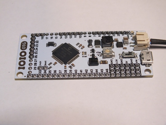
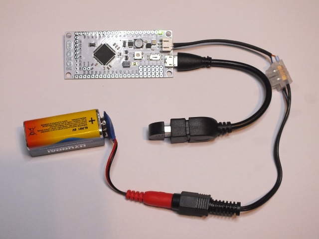
I saw IOIO in use with Android tablet, and wanted to get my own because it looked nice product when working with Android (Arduino USB connection does not work with many Android devices). The current up to date version of IOIO is IOIO-OTG. I found that I could get IOIO-OTG cheaply from dx.com, so I ordered it. After some weeks I received the product. Here is picture of IOIO-OTG board I have. I have connected my homemade power cable to it from 9V battery or 5-12V mains adapter.
First Android tests failed. None of the Android devices could find the IOIO board. ![]() And this was supposed to be easy-to-use product that was specifically designed for Android device. I wired the IOIO-OTG board to Android tablet with the supplied OTG cable connected to USB-microUSB cable (that connects to tablet). I tried several cables and several apps, but no success. The questions are is the board damaged or is there some software configuration problem?
And this was supposed to be easy-to-use product that was specifically designed for Android device. I wired the IOIO-OTG board to Android tablet with the supplied OTG cable connected to USB-microUSB cable (that connects to tablet). I tried several cables and several apps, but no success. The questions are is the board damaged or is there some software configuration problem?
If it does not work with Android device, does it work with PC? So I decided to check if it works on Windows PC, because IOIO-OTG offered also this connectivity mode. I started Windows testing using instructions from Running IOIO-OTG on a Windows PC page. First I made sure that the IOIO-OTG is switched to Auto (A) mode. The board needed drivers, and I got driver from https://github.com/ytai/ioio/blob/master/driver/ioio.inf (saved the data to file ioio.inf and made Windows to install driver from there). Running example program HelloIOIOSwing from IOIO software packet worked! So the board is not completely broken.
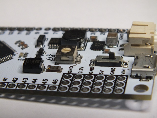
Back to Android USB testing. I used IOIO Controller (0.69 Euros) and some free IOIO software to do testing again on Android. No luck with anything. I did some hardware debugging. I used my USB Power Current Voltage Tester to see that there was no +5V power coming out of the USB connector (IOIO should supply +5V when it is in USB host mode). I did some debugging with help from multimeter and IOIO-OTG schematic: Found out that the output FET does not get right driving voltage level to turn on. It turned out that one contact on the output current adjustment potentiometer was not soldered properly:
When I fixed the soldering issue, the board started to work as it should. Android devices found it nicely and IOIO software could find it. It turned out that IOIO Controller looked like best control software for testing.
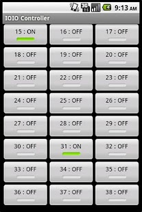
The IOIO Controller allowed to control the state of the different pins to use different purposes. I could use pins 10-15 as PWM output I can control,pins 15-38 as digital outputs and pins 39-46 as analog inputs. The software had also digital input reading mode, but I could not get it to show any valid input states. The I/O pins on the IOIO-OTG are designed for 3.3V LVTLL signal levels. In my tests the PWM outputs generated the PWM signal at 100 Hz frequency which is suitable for example for LED dimming and should be suitable for hobby servo controlling at 1-2 ms pulse lengths (if you need to get different PWM frequency like commonly used 1 kHz as given by Arduino Firmata or used by some industrial PWM systems, you need to make your own program).
IOIO-OTG supports also wireless Bluetooth connection option by plugging USB-Bluettooth adapter to it. I wanted to try it as well. I used cheap Super Mini Bluetooth 2.0 Adapter Dongle (Vista Compatible) that I wired to IOIO-OTG with USB-OTG cable. I used instructions from IOIO Over Bluetooth for Android page to get started. I used USB male-micro-A-to-female-A adapter cable to connect Bluetooth Adapter Dongle to IOIO-OTG.The board worked well in Automatic mode (A) and current limiting potentiometer at almost maximum setting.
Before starting using the control software, I needed the IOIO board with USB dongle to be “paired” with my Android device. I went to Settings > Wireless & networks > Bluetooth settings menu. I found device called IOIO. I clicked the IOIO in order to pair it with PIN code 4545.
I used IOIO Bluetooth Control Device to control the IOIO-OTG from Android smart phone. It worked well. I also tried IOIO RC Remote Control software, which also worked. Now I have working wireless IO that I can control from Anrdoid device.
10 Comments
Tomi Engdahl says:
For more testing this app looks interesting:
IOIO Script – Easy Programming
https://play.google.com/store/apps/details?id=com.smartphoneremote.ioioscript&hl=fi
Easily write programs for the SparkFun IOIO board using JavaScript.
Ytai says:
Also check out the newly announced protocoder, which is a JS environment for writing Android app including using the IOIO, all done from a Web-based IDE served from the Android:
http://protocoder.org/
Tomi Engdahl says:
Look interesting. I will check that out.
Ytai says:
[I'm the guy who designed the IOIO]
Note that you can get a IOIO-OTG for $30 from SeeedStudio. Unlike the DX version and other questionable clone, the Seeed boards are manufactured with the best standards and are individually testing.
While I don’t personally care about DX making and selling my design, it is a bit unfortunate that some people who are not as persistent as you might conclude that this is a bad product in general as opposed to considering that they bought it from a cheap-and-crappy vendor.
Thanks for the review! I hope you have fun with the board now that you have it up and running.
Tomi Engdahl says:
Thank you very much for your feedback on this.
Tomi Engdahl says:
Here is link to IOIO oroducts from SeeedStudio
http://www.seeedstudio.com/depot/s/IOIO.html?search_in_description=0
Tomi Engdahl says:
Link to one interesting project that uses IOIO
Timelapse Photography on an Android-Powered Dolly
http://hackaday.com/2014/10/11/timelapse-photography-on-an-android-powered-dolly/
http://raspberrywood.com/android-timelapse-dolly/
[Bryce] opted for controlling the rig through Android and a IOIO board. This gives the project a lot of options for communications, including Bluetooth. The whole thing is powered by a 19V battery pack.
Tomi Engdahl says:
IOIO Bluetooth Device Control
https://play.google.com/store/apps/details?id=ioio.bluetooth.control
IOIO Script – Easy Programming
https://play.google.com/store/apps/details?id=ioio.bluetooth.control
Joe says:
Did the 9v battery work on the ioio board? I have a 5volt ioio board and I’m having doubt whether I should connect it or should I use a volgate regulator to step down the voltage.
Tomi Engdahl says:
9V battery works when connected o Vin pin.
https://github.com/ytai/ioio/wiki/Power-Supply says:
The most common way of powering the IOIO is by connecting a DC voltage source, anywhere between 5V-15V, with the (+) side going to one of the three pins marked as “VIN” and the (-) side going to one of the nine pins marked as GND.
Pinout:
https://github.com/ytai/ioio/wiki/Getting-To-Know-The-Board