Pulse generator is an electronic test equipment used to generate rectangular pulses. Pulses are typically injected into a device that is under test and used as a stimulus or clock signal or analyzed as they progress through the device, confirming the proper operation of the device or pinpointing a fault in the device. Typical application field that needs fast pulses is Time-domain reflectometry (TDR) that is a measurement technique used to determine the characteristics of electrical lines by observing reflected waveforms.
I have build and used Time Domain Reflectometer (TDR) pulse generator for generating pulses, and written some TDR signal generator related postings to this blog. Often when you have one tool, then you want something better or different. I have been for some time though of building an avalanche pulse generator using avalanche transistor.
EEVblog #306 – Jim Williams Pulse Generator video shows testing of the Jim Williams designed pulse generator from Linear App Note 47:
As shown Avalanche transistors can be used to generate fast rise time pulses, but because avalanche transistors are no longer popular and are hard to get, I decided to try something similar with more easily available components. Avalanche Pulse Generator page says that 2N2369 transistor is typically used, getting sub-ns pulses quite easily, but the common 2N3904 works, at somewhat higher voltage and probably a bit slower.Avalanche Pulse Generator Build Using 2N3904 web page saysmost general purpose NPN transistors such as 2N3904, 2N2222, SS9013, etc. can be used in avalanche mode as well. Junk box 2N3904 Avalanche Pulse Generator web page recommends BFR505 (simple 30v avalanche of ~200-300pS).
I decided to test with components I have easily available. Avalanche Pulse Generator Build Using 2N3904 and Avalanche Pulse Generator web page offer plans for a nice avalanche pulse generator using easily available components that I happened to have lying around. Avalanche Pulse Generator Build Using 2N3904 version of a circuit has become popular following an application note (AN72) by Jim Williams and was further publicized via this EEVBlog video.
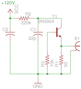
The circuit works so that R2, C1 along with the NPN transistor form a relaxation oscillator. The capacitor gets charged via R2 and then rapidly dischargs when the collector-emitter voltage reaches the avalanche voltage (typically around 100V). R3 biases the collector-base junction. The circuit should give approx. 300pS rise time.
Warning: This circuit works on potentially dangerous voltages! Do not touch any parts of the circuit when it is powered. Keep in mind all the electrical safety issues. You must understand what you are doing to be safe.
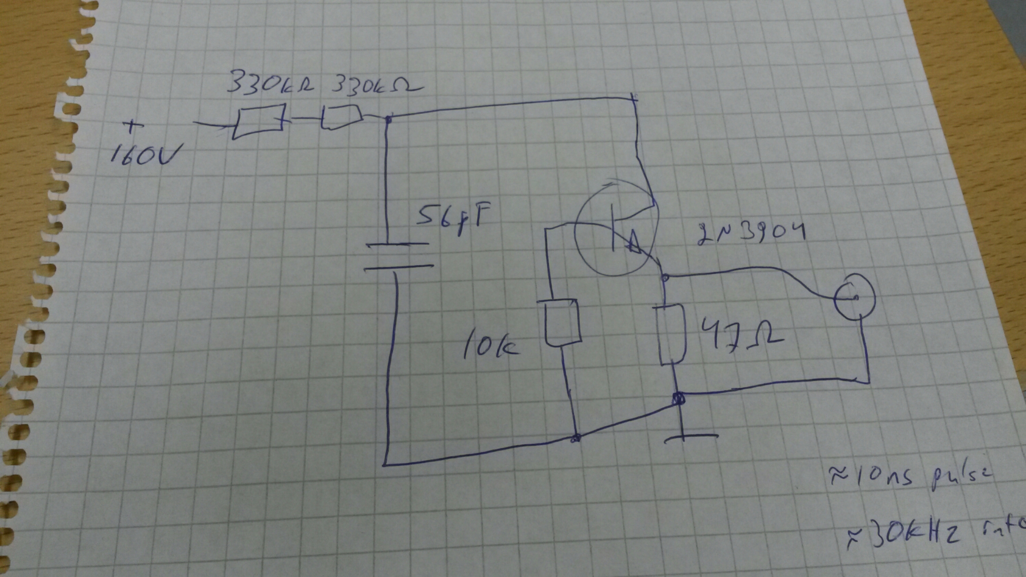
I built my first circuit prototype to solderless breadboard, which is not the right board for this kind of fast pulse circuit due to to relatively large parasitic capacitance compared to a properly laid out PCB (approx 2pF between adjacent contact columns). I powered the first prototype circuit with current limited 250V DC power source (I used my insulation resistance meter for as power source) and tried to measure the output with my 100 MHz digital oscilloscope. I did not first get anything sensible to scope screen, but after chaging the main capacitor to bigger one, I go the circuit to work OK and give such pulse lengths that they can be nicely detected with my oscilloscope. So with the testing I ended with the following circuit design that gives short pulses at around 30 kHz repeat rate:
And here is my ugly but low parasitic capacitance real-life implementation of the circuit:
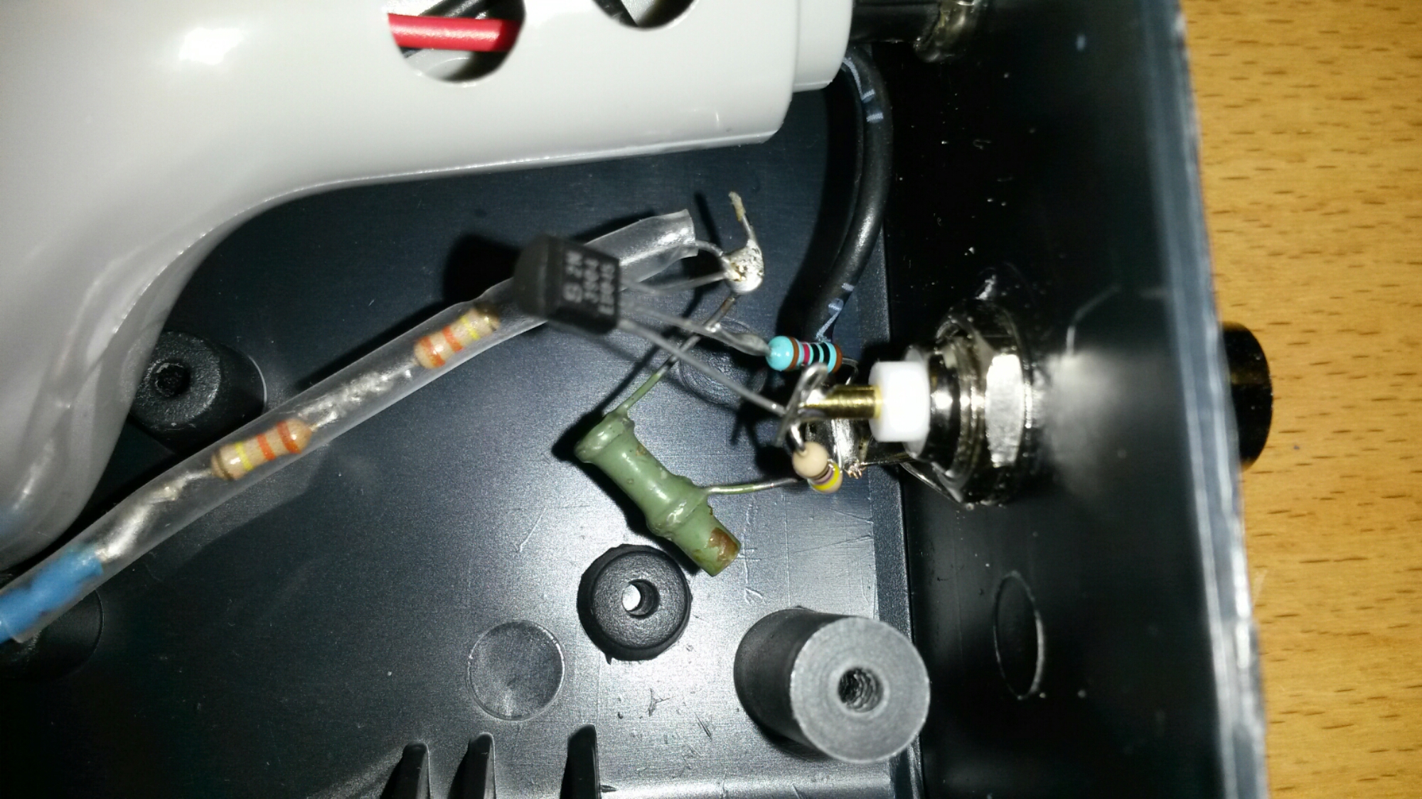
For safety reasons there are two current limiting resistors in series in the circuit and they are well insulated (with heat shrinking tube). The idea is that failing of any single component does not make the circuit itself or the output signal immediately dangerous. The current limiting resistors limit the DC current that can go to circuit ouutput to fraction of mA in case something goes terribly wrong (47 ohms resistor goes open circuit). The energy stored to 56 pF capacitor is very low.
My initial testing with 100 MHz digital oscilloscope would indicate that the pulse length would be around 10 ns, pulse amplitude something around 50 V (not very accurate) and repeat are around 30 kHz.
So I needed to measure performance with some better (more expensive) instrument. Here are some test results of the output waveform made with high speed oscilloscope:
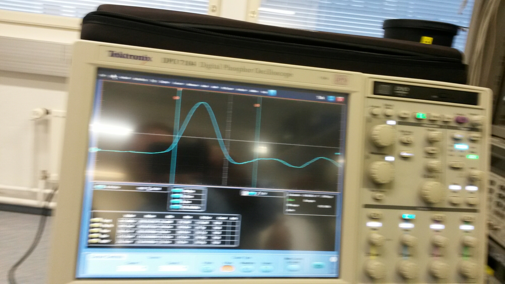
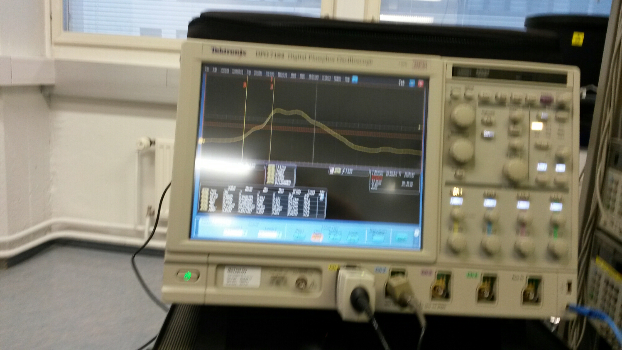
I could not measure the signal amplitude directly, because the signal amplitude (tens of volts) was too high to the high speed active probes. I did the measurements with 10 dB 50 ohms attenuator connected to signal generator output (I got around 20V peak signal amplitude from the attenuator output).
The rise time of the signal (10-90%) ended up being around 1 nanoseconds (considerably slower than expected around 300 ps). The pulse length was approximately 6 nanoseconds.
Here is picture of the device put into nice case (Bebek G010B = Kemo G010):

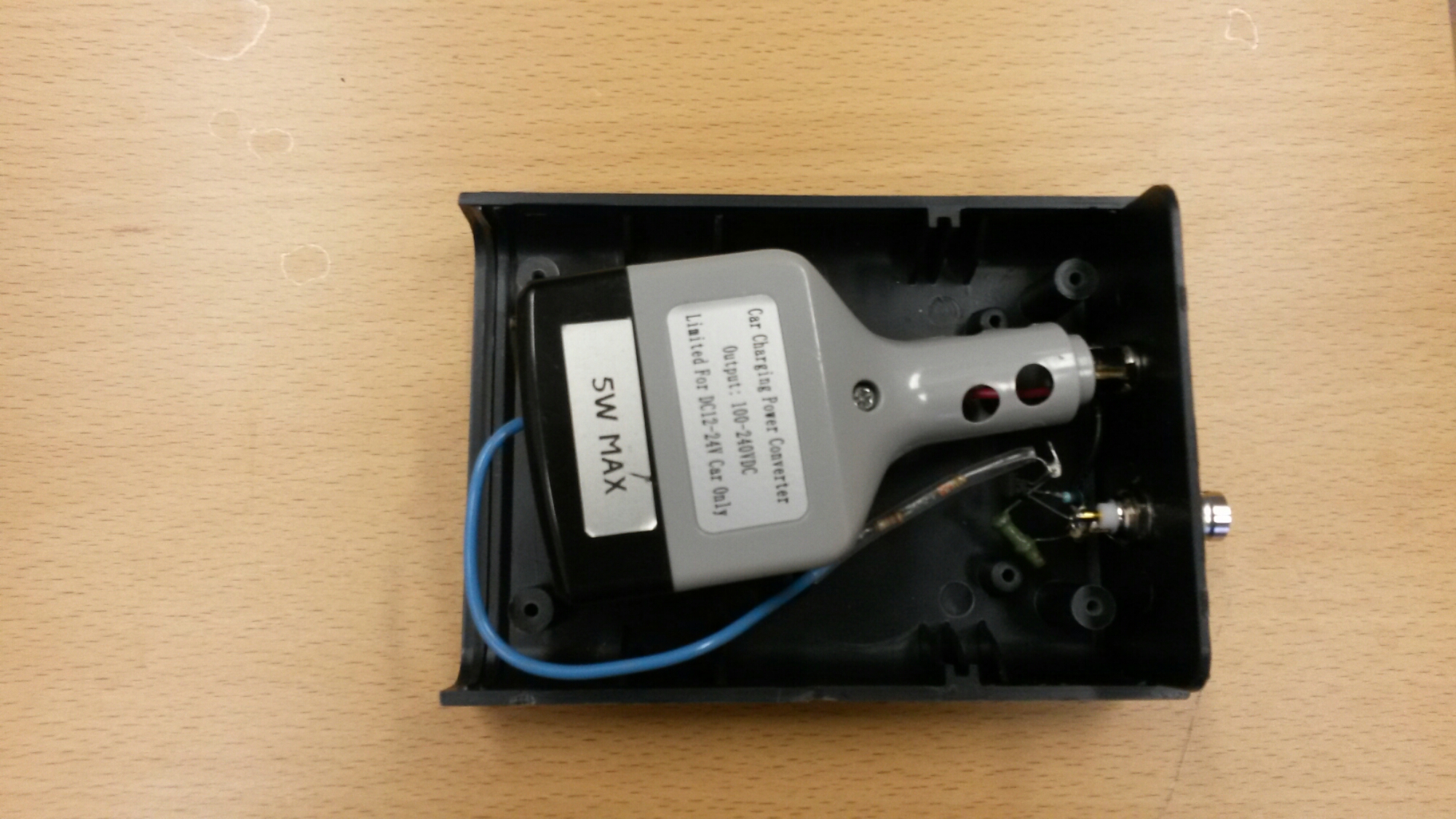
Here are the disty details inside the case. The circuit is dirty because I used the parts I had. To get the over 100V voltage, I needed a DC/DC converter. I had lying around an old mechanically broken “Car Charging Power Converter” device that is designed to convert car 12V DC to voltage that can be used with smart phone chargers and such small devices that normally work from 110/230V AC – this particular cheap 5W device converts the 12-24V power to 100-240V DC (that would work with most small switch mode power supplies originally designed for 100-240V AC input). This specific converter seemed to work well with 9-12V, and give out aroudn 160V DC out, exactly what I needed for my avalanche circuit. I decided to keep most of the original converter case and have some part of circuit well insulated so that the circuit would not be too big hazard when the box case is open.
I have now a working pulse generator with around 1 nanosecond rise time.
Links for more information:
https://en.wikipedia.org/wiki/Avalanche_transistor
http://www.kerrywong.com/2013/05/18/avalanche-pulse-generator-build-using-2n3904/
https://hackaday.io/project/2226-avalanche
http://hackaday.com/2013/08/06/avalanche-pulse-generator-design/
http://hackaday.com/2016/10/04/a-quickly-hacked-together-avalanche-pulse-generator/
https://dodgyengineering.com/2016/08/10/junk-box-2n3904-avalanche-pulse-generator/
http://www.eevblog.com/forum/projects/transmission-line-avalanche-pulse-generator/
http://dangerousprototypes.com/blog/2013/07/20/avalanche-pulse-generator-and-some-scope-porn/
http://dangerousprototypes.com/blog/2013/06/26/avalanche-pulse-generator-build-using-2n3904/
http://hackaday.com/2016/10/04/a-quickly-hacked-together-avalanche-pulse-generator/
http://www.holmea.demon.co.uk/Avalanche/Avalanche.htm
http://www.jensign.com/avalanchepulsegenerator/index.html
https://hackaday.io/project/15500-avalanche-pulse-generator
http://www.eevblog.com/2012/07/06/eevblog-306-jim-williams-pulse-generator/
http://hackaday.com/2016/09/29/testing-the-speed-of-light-conspiracy/
19 Comments
Tomi Engdahl says:
“TDR” or Time Domain Reflectometer, build and use this circuit.
https://www.youtube.com/watch?v=I1gfUNh5PJQ
Time Domain Reflectomety
https://www.youtube.com/watch?v=sqTR7FMaD68
Tomi Engdahl says:
Detect and analyze EFT events
http://www.edn.com/design/test-and-measurement/4443199/Detect-and-analyze-EFT-events?_mc=NL_EDN_EDT_EDN_weekly_20161229&cid=NL_EDN_EDT_EDN_weekly_20161229&elqTrackId=db8ae7162560484792b9a8057412feaa&elq=6a0ece316c0842b4a0808c224412b15e&elqaid=35341&elqat=1&elqCampaignId=30890
Energy bursts from electrical fast transient (EFT) pulses can couple into nearby electrical paths, risking digital signal corruption of electronic systems, leading to potential malfunctions such as unintended latching or resets. You can use an oscilloscope to capture, display, and analyze EFT events. Many EMC engineers are, however, unaware of this capability and the benefits it provides. By using features found on many oscilloscopes, you can trigger on EFT events even when a long time might pass between them.
You can also detect “runt” pulses caused by EFTs. Finally, you can calculate the energy in an EFT pulse. With that information, you can make design changes to improve EFT immunity. EFT events occur when current flow is instantaneously interrupted, resulting in arcing between contacts that can disrupt circuits and systems. The arcs create EM fields that can then couple into circuit paths through cables, traces, and connectors. Common causes for EFT include relay-contact bounce, opening and closing of circuit breakers, switching of inductive loads, and powering down equipment. Breakdown of the air gap between electrical contacts often triggers a rapid burst of EFT pulses.
Tomi Engdahl says:
Here is pulse generator that supports external triggering:
Pulse generator verifies test setups (Jim Williams)
http://cms.edn.com/ContentEETimes/Images/01MDunn/DI/DI_ESC_Williams_pulsegen.jpg
Tomi Engdahl says:
Step recovery diodes are also used to generate fast pulses, so this article is somewhat related:
Designing a Step-Recovery-Diode-Based Comb Generator
http://mwrf.com/analog-semiconductors/designing-step-recovery-diode-based-comb-generator?NL=MWRF-001&Issue=MWRF-001_20170309_MWRF-001_393&sfvc4enews=42&cl=article_2&utm_rid=CPG05000002750211&utm_campaign=10018&utm_medium=email&elq2=42dbb3faa6b7476bb888c96aec9cb6e8
By leveraging advanced software, accurate results were obtained in the design and testing of a comb generator.
Multiplier (and comb generator) circuits are reactively terminated at the higher-order harmonics at the output port.
Tomi Engdahl says:
Notes in the similar power supply I used to generate high voltage:
Inside a slightly bizarre car to “mains” adaptor.
https://www.youtube.com/watch?v=-3A2H0Z5j_w
I’m not sure what to make of this. It’s technically intriguing but I’m struggling to work out its purpose other than possibly being for
running older plug-in power supplies for equipment that doesn’t use a standard USB style connector.
Tomi Engdahl says:
High-voltage power pulse circuit
http://www.electronicdesign.com/power/high-voltage-power-pulse-circuit?code=UM_Classics02118&utm_rid=CPG05000002750211&utm_campaign=15650&utm_medium=email&elq2=5d57535c6a254ed1a557490adc377cd7
Fast rise-time high-voltage pulses have many uses ranging from EMC testing to device characterization. The simple, low-cost circuit described here deals with the latter. It’s able to generate 0- to 1000-V pulses with currents up to 50 A, and a rise time of 100 ns for 800 V/30 A. The output can withstand short circuits, and capacitive and inductive loads. Pulse length and repetition rate are determined by an optically isolated TTL-input signal. Commercial equipment like pulse/function generators or a PC can be connected to this input. The pulse’s amplitude is set by the HV supply; a low-cost photomultiplier-type supply (0, 5 ..5 mA) can be used when repetition rates are below 20 Hz.
Circuit layout is very important—a groundplane is needed to keep inductance low.
Tomi Engdahl says:
“TDR” or Time Domain Reflectometer, build and use this circuit.
https://www.youtube.com/watch?v=I1gfUNh5PJQ
This is a simple avalanche type, TDR ( Time domain reflectometer ) which allows you to analyze many different issues with coaxial cable.
Tomi Engdahl says:
“TDR” or Time Domain Reflectometer, build and use this circuit.
https://www.youtube.com/watch?v=I1gfUNh5PJQ
Tomi Engdahl says:
TDR with different Oscilloscopes.
https://www.youtube.com/watch?v=nHHWYYZdN0A
Trying the TDR ( Time Domain Reflectometer ) with different oscilloscopes. First, the old Tektronix 547 shows it’s stuff, then the TDS220 oscilloscope, soon after.
Tomi Engdahl says:
“TDR” or Time Domain Reflectometer, build and use this circuit.
https://www.youtube.com/watch?v=I1gfUNh5PJQ
This is a simple avalanche type, TDR ( Time domain reflectometer ) which allows you to analyze many different issues with coaxial cable. This is the first video in a small series. I will also cover DTF, or “Distance To Fault,” how to determine Impedance, using this TDR to check an oscilloscope graticule, looking for hidden barrel connectors, or “a splice,” and so on….
Tomi Engdahl says:
Time Domain Reflectomety
https://www.youtube.com/watch?v=sqTR7FMaD68
Covers how to perform the function of a TDR by using an oscilloscope
and a pulse generator. Understanding the material in this video will
help you to understand how an actual TDR works.
Tomi Engdahl says:
Example of low voltage avalanche circuit:
Transistor Avalanche Disaster
https://www.youtube.com/watch?v=DCc1zxuAsmw
30 or 40 transistors die in reverse biased avalanche breakdown catastrophe. You told me not to put components into a live circuit, and on this occasion, you were right. Also, some clever 1-transistor oscillators
Tomi Engdahl says:
Testing The Speed-of-Light Conspiracy
https://hackaday.com/2016/09/29/testing-the-speed-of-light-conspiracy/
http://www.jensign.com/sol/index.html
Tomi Engdahl says:
http://www.kerrywong.com/2013/05/18/avalanche-pulse-generator-build-using-2n3904/
Tomi Engdahl says:
https://www.researchgate.net/figure/Complete-avalanche-pulse-generator-circuit_fig1_251842621
Tomi Engdahl says:
https://electronicprojectsforfun.wordpress.com/pulse-generators/avalanche-transistor-pulsers/
Tomi Engdahl says:
Sean Breheny 2N2369 , BFG541 are good candidates. the SGS thomson 2N2369 work really well (gold pins) . the onsemi were slower (larger die inside) . keep in mind that none of these transistors are really designed for this. They will eventually die. There are special avalanche transistors like the FMMT413 or ZTX415 / FMMT415 . True avalanche transistors need a controlled pulse on their base to “fire” you can’t simply put a high voltage on them. An avalanche transistor has a negative resistance (called secondary breakdown) in the breakdown curve. You need to tune the collector voltage so that you stay just below the avalanche threshold. if then fire the base the transistor will avalanche. They need about 220 volt collector voltage. below that they just switch fast but do not enter avalanche operation.
Source https://www.facebook.com/share/p/fcdq61trfsryz9x4/
Tomi Engdahl says:
50ps rise time using an ultra fast SiGe comparator http://www.starlino.com/build-a-really-fast-pulse-generator-50ps-rise-time-using-an-ultra-fast-sige-comparator.html
Tomi Engdahl says:
Does this work? The circuit idea is right, but usually somewhat more than 9V voltage is needed for that usually 12-18V.
How this bc547 LED flasher work with no Base biasing? : r/AskElectronics https://share.google/4Be9vW6NYHqcp69Hy