An optical power meter (OPM) is a device used to measure the power in an optical signal. The term usually refers to a device for testing average power in fiber optic systems. Power meters are part of the toolbox essentials for all technicians installing or maintaining any type of fiber networks. They are used to measure that the optical signal level is in right range (not too high or too low). Together with a known level optical signal source and optical power meter can be used to measure fiber signal attenuation.
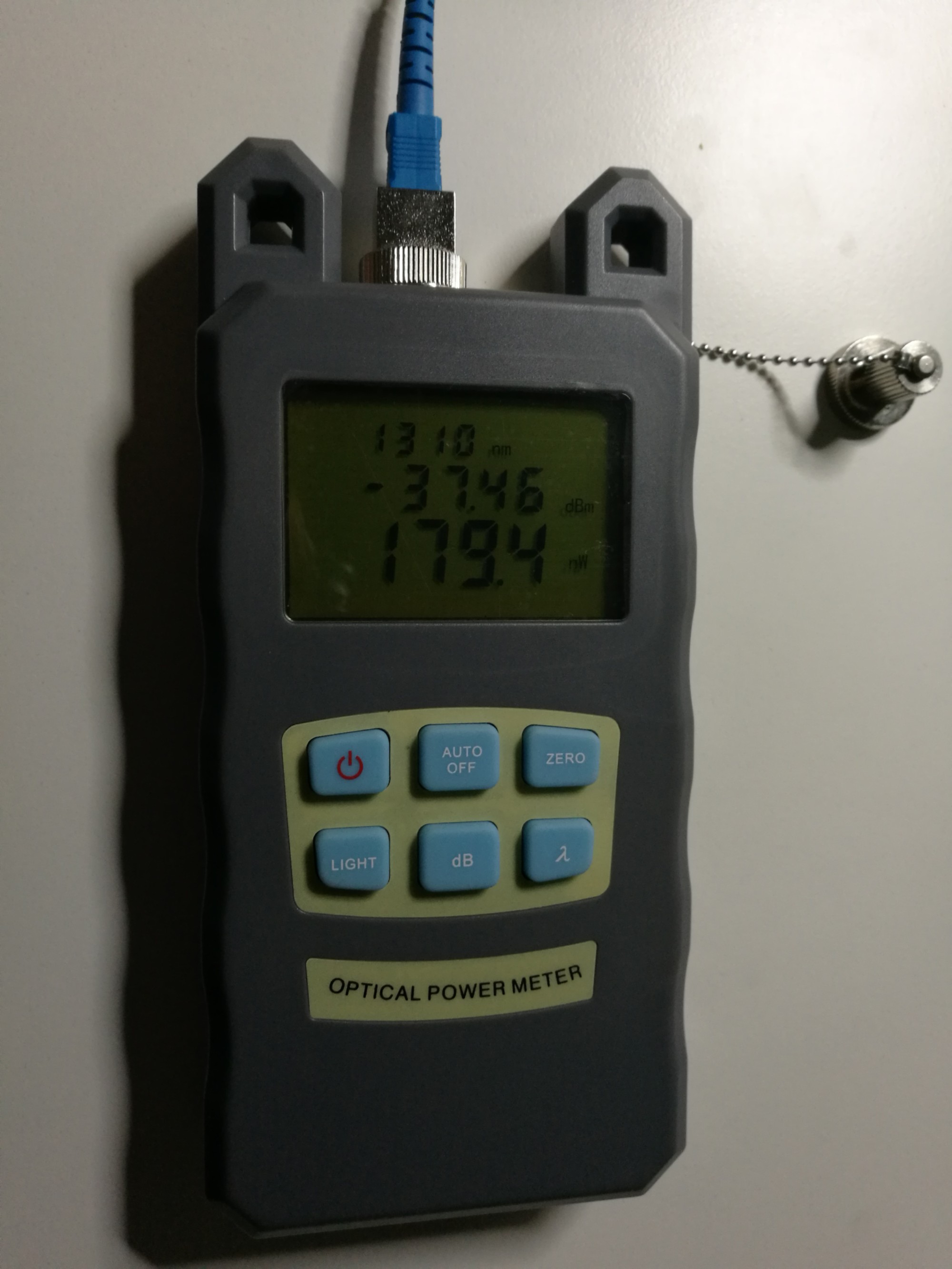
When I was in need for a fiber optic power meter, I found this pretty cheap model AUA-70A Fiber Optic Optical Power Meter Cable Tester Networks FC/SC Connectors -70 – +10dBm. It looks like a slim upgraded version of CommScope Tyco AUA-70A Power Meter.
http://www.banggood.com/AUA-70A-Fiber-Optic-Optical-Power-Meter-Cable-Tester-Networks-FCSC-Connectors-70-10dBm-p-1032244.html?p=27131452996820140438
User self-calibration function
Linear (mW) and nonlinear index (dBm) displayed simultaneously
Unique FC / SC / ST generic interface, without complicated conversion
The optional automatic shutdown function
Optional on / off backlight display
Test range is -70dBm~+10dBm.
This optical power meter can measure power of the light at 7 wavelengths: 850/980/1300/1310/1490/1550/1625nm
Powered with two AA batteries
The display is time averaged power of signal on fiber. A typical OPM measures accurately under most conditions from about 0 dBm (1 milli Watt) to about -50 dBm (10 nano Watt), although the display range may be larger (with this meter 70dBm~+10dBm)
Here is one setup where I test the meter with cheap fiber visual fault locator as signal souce:
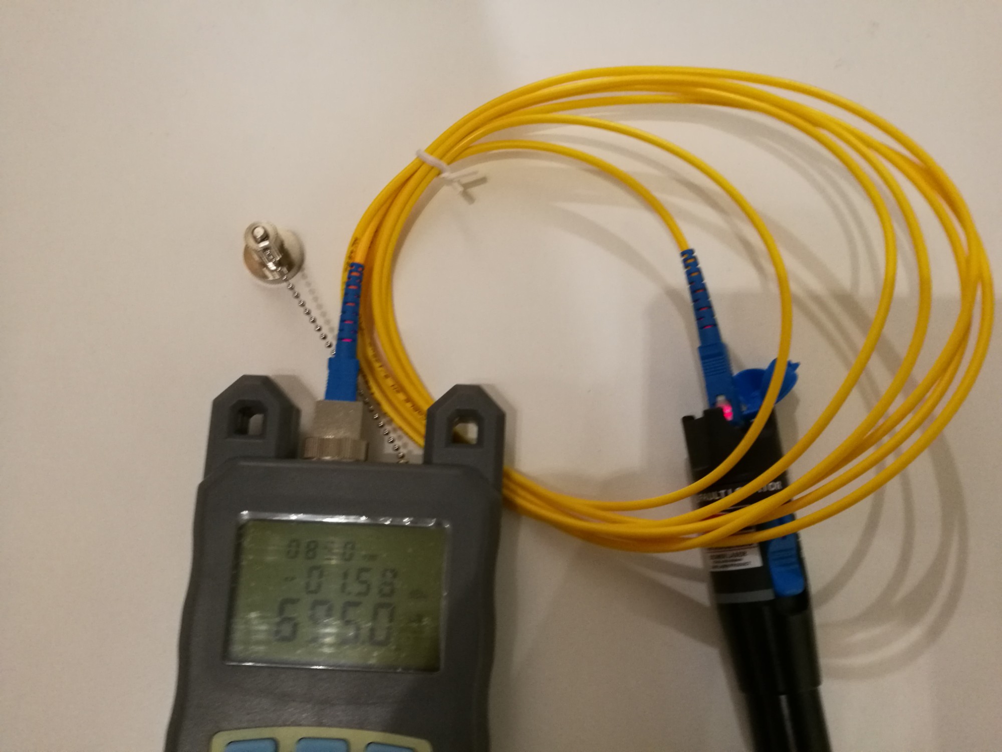
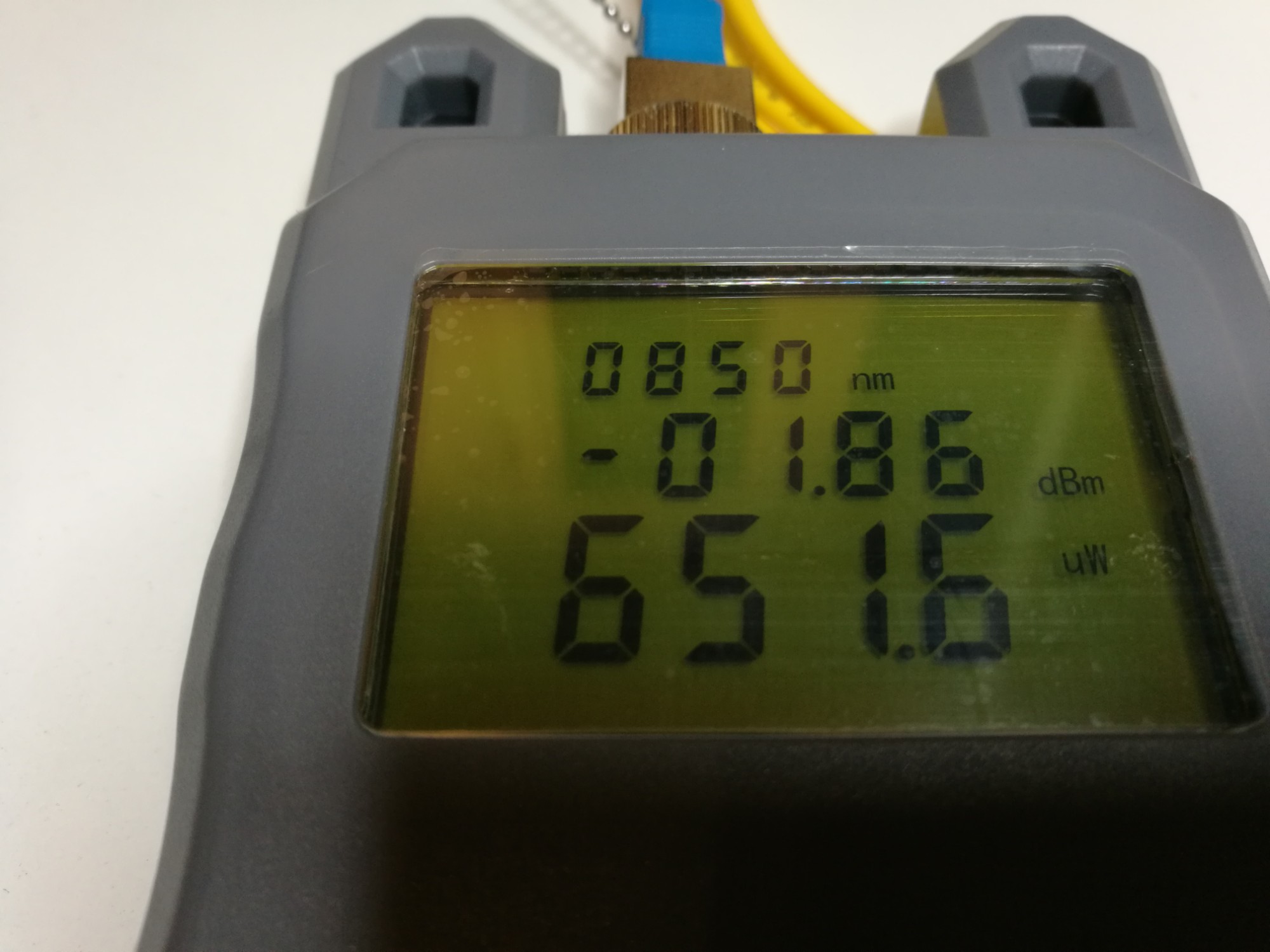
All the signal wavelenghts are measured with the same sensor, which I quess is InGaAs detector. Basically this meter consists of a photodiode, amplifier and display unit. This meter is traditional optical power meter that responds to a broad spectrum of light, however the calibration is wavelength dependent. Before making measurement, you need to set the meter to correct wavelength (test wavelength is usually known so not usually an issue) before you can get accurate results – if you select wrong wavelenght you will get wring results. For example with exactly same signal I get at 850 nm settings several times higher power reading than with 1310 nm setting.
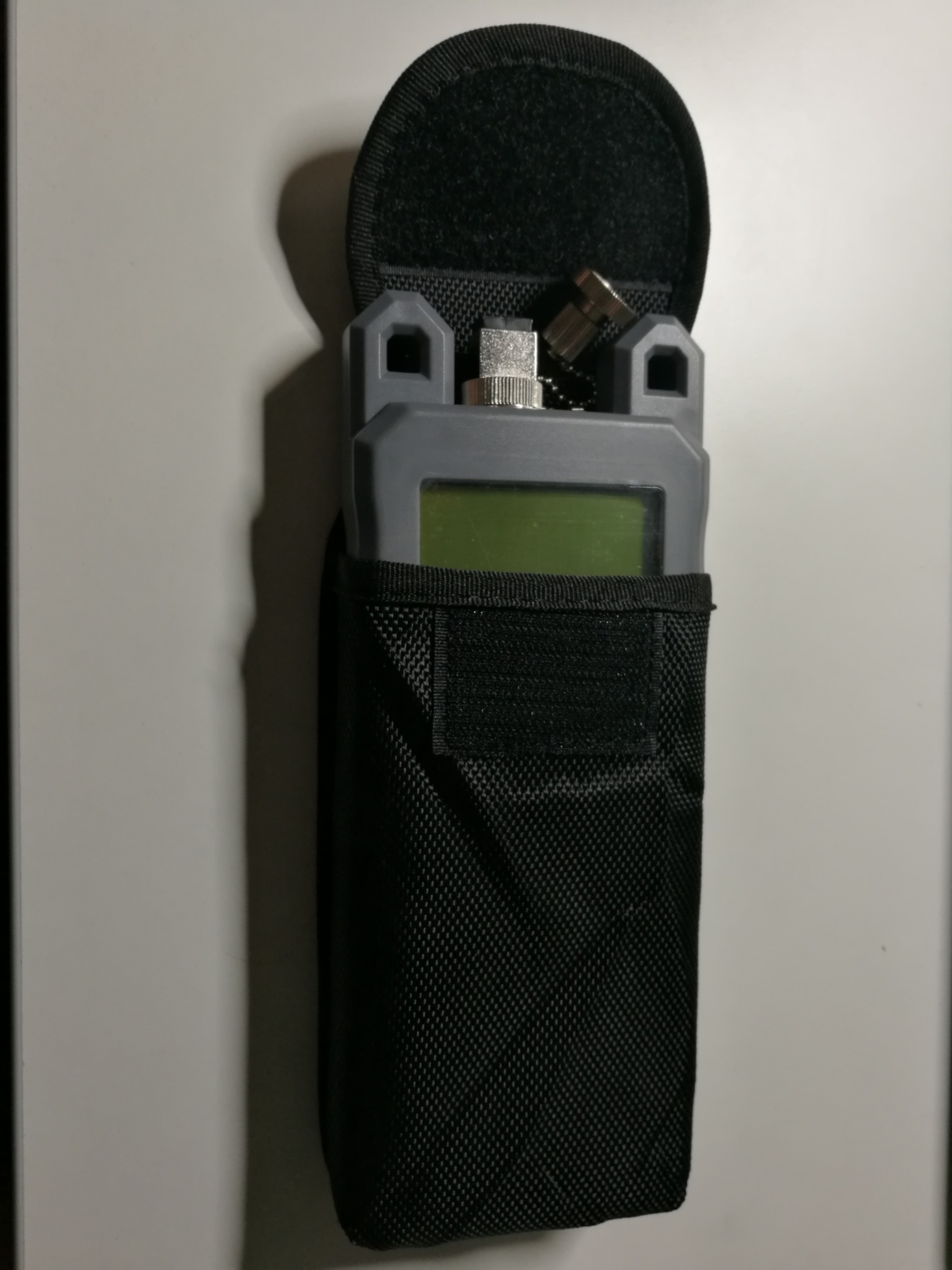
The meter comes with small bag that provides some protection to the device:
Pros:
- Meter works well
- Cheap
Cons:
- The case plastic is feels cheap, does not feel high quality
- What is actual accuracy this provides?
More related material: Links to information on fiber Ethernet signal levels:
https://www.ccontrols.com/pdf/abc3.pdf
http://etherealmind.com/can-fibre-optic-ethernet-cables-be-longer-than-the-standard/
28 Comments
Tomi Engdahl says:
Here is an interesting article on DIY fiber power meter alternative (considering the cheap price of ready made it might not make sense trying to build your own):
Hackaday Prize Entry: An Optical Power Meter
https://hackaday.com/2017/09/14/hackaday-prize-entry-an-optical-power-meter/
This is the type of crowd that’s famous for building their own test equipment. If you need a way to program a flash chip, don’t go out and buy one — you can just build one. Need a spectrum analyzer? You can build that out of copper clad board. For his Hackaday Prize entry, [oakkar7] is building an optical power meter, capable enough to do futzy fiber work, but still completely DIY.
[oakkar]’s optical power meter uses these SPF transceivers, tied together with a fairly simple circuit consisting of an Arduino, a few tact switches, a Nokia LCD, and an FTDI UART.
Optical Power Meter (with SFP and DDM protocol)
https://hackaday.io/project/21599-optical-power-meter-with-sfp-and-ddm-protocol
DIY Optical Power Meter with SFP (Small Form-factor Pluggable transceiver) and DDM (Digital diagnostics monitoring ) protocol
To build DIY optical power meter with standard SFP module and Arduino
- Can measure optical power in dbm and watt
- Can Enable/Disable TX power output (laser source)
- Can debug via UART
And Arduino Library
- a lib for SFP/DDM interfacing (not only optical sfp transceiver
- to interface and interpret DDM (Digital Diagnostics Monitoring ) protocol (which used in most optical fiber communication) scheme and format
- to debug, monitor, detect alarm and control SFP via DDM
- to extend the capability of handling data TX/RX interface (Arduino data over optical fiber)
Initial concept
- Most optical fiber module in today communication used from factor called SFP (small form-factor pluggable) physical interfacing. SFP is widely used in many switches, routers and many telecom devices. SFP modules comes with various transceivers option from electrical to optical interfaces such as Ethernet, Giga-bit Ethernet, optical fiber , SONET, STM, etc.
- Although transceivers are different, all SFP modules are controllable with a standard protocol named DDM (Digital Diagnostics Monitoring).
- DDM is The operating and diagnostic information is monitored and reported by a microcontroller inside the transceiver, which is accessed via a 2-wire serial bus (also known as “I2C” or “I2C” protocol).
- I2C bus interfacing is easily done by Arduino
Tomi Engdahl says:
here are four special wavelengths that you can use for fiber optic transmission with low optical loss levels, which this table lists:
Windows Wavelength Loss
1st wavelength 850nm 3dB/km
2nd wavelength 1310nm 0.4dB/km
3rd wavelength 1550nm (C band) 0.2dB/km
4th wavelength 1625nm (L band) 0.2dB/km
Source: https://www.cisco.com/c/en/us/support/docs/optical/synchronous-digital-hierarchy-sdh/29000-db-29000.html
Tomi Engdahl says:
Troubleshooting TechNotes
Introduction to Optical Fibers, dB, Attenuation and Measurements
https://www.cisco.com/c/en/us/support/docs/optical/synchronous-digital-hierarchy-sdh/29000-db-29000.html
Anthony says:
Buongiorno,
vorrei sapere se esiste un libretto di conformità di questo prodotto
grazie,
Anthony
Tomi Engdahl says:
The product package had one A4 size paper written in Chinese. It looked like instruction.
I can’t read Chinese, so I don’t know if there is any conformity information in it or not.
Tomi Engdahl says:
Lightwave Multimeter Teardown
https://hackaday.com/2021/07/06/lightwave-multimeter-teardown/
Tomi Engdahl says:
Fiber Identifier
https://www.huihongfiber.com/fiber-optic-identifier.html
Fiber identifier is an essential installation and maintenance instrument which can identify the optical fiber by detecting the optical signals transmitted through them,during this process the fiber optic identifier generate no harm or damage to the fiber cable and it do not need opening the fiber at the splice point for identification or interrupting the service.This fiber identifier detects frequency tones at 270Hz, 1KHZ, 2KHZ, when traffic is present on the fiber under test, an audible tone can be heard. In the meantime, it can identify the traffic direction that indicated by LED with illumination.
This optical fiber identifier features core power display of the fibers (-30~+5dBm),low bending loss and high efficient output,easy to replace adaptors,hand held type,portable, compact size ,small weight and easy-to-use, it is a wonderful and much economic tool used in fiber optic network maintenance.
What is The Fiber Identifier
https://www.fiber-optical-networking.com/what-is-the-fiber-identifier.html
The Fiber Identifier acts as the fiber optic installer or technician’s infrared eyes. By placing a slight macrobend in an optical fiber or fiber-optic cable, it can detect infrared light traveling through the optical fiber and determine the direction of light travel. Some fiber identifiers can also detect test pulses from an infrared (800–1700nm) light source.
The fiber identifier typically contains two photodiodes that are used to detect the infrared light. The photodiodes are mounted so that they will be on opposite ends of the macrobend of the optical fiber or fiber-optic cable being tested. The electronics in the fiber identifier measure the detected light energy and display the direction of light travel through the optical fiber.
The fiber identifier can also be used with external light source. Often the external light source is an Fiber OTDR. Many OTDR manufacturers build or program in a pulsed output function. When set for a pulsed output, the OTDR emits a continuous pulse train at a predetermined frequency. The electronics in the fiber identifier can detect preset frequencies and illuminate the corresponding LED. This feature can be very helpful when you are trying to identify an unmarked tight-buffered optical fiber within a bundle of tight-buffered optical fibers.
The fiber identifier can be used with the OTDR to narrow down the location of a break in an optical fiber when a VFL is not available or when the light from the VFL is not visible through the jacket of the fiber optic cable.
Tomi Engdahl says:
https://www.huihongfiber.com/fiber-identifier.pdf
Tomi Engdahl says:
KFI 40 Komshine optical fiber identifier
https://www.youtube.com/watch?v=bR0G6Jy4YsY
Suitable for 0.25/0.9/2.0/3.0mm Easy test directly,convenient and efficient
Identifies dominant traffic direction, audible alarm
Low false detection & insertion loss
Battery low indication
KFI-40 Optical Fiber Identifier operation video
https://www.komshine.com/resources/video/17.html
Tomi Engdahl says:
Specification:
Identified Wavelength Range 750nm-1700nm
Insertion Loss 1.0dB
Fiber Type <3mm Fiber
https://www.aliexpress.com/i/32935059543.html
Tomi Engdahl says:
https://www.komshine.com/test/kfi-40.html
Tomi Engdahl says:
FTTH Making and Passive Node Fault Checking | How to detect and fix faulty FTTH | Cable Splicer Tech
https://www.youtube.com/watch?v=0fbBuDQrZKQ
Its an very important video.. At present single out passive node cost around Rs. 120 to 200.. If any small resistant/capasitor/diode problem can be rectified by Rs. 10 cost, no need to replace.. Most of the operator (including me) doesnt know, how to use multimeter, request you to make an brief video, will helpful for us… Thanks…
Passive FTTH Nodes Review – PART 3 | 1 OUT vs 2 OUT vs 3 OUT vs 4 OUT Comparison in Cable TV Tamil
https://www.youtube.com/watch?v=HpK9TZpb7W4
Tomi Engdahl says:
How to use Optical Fiber Identifier Orientek TFI 40 Live SingleMode Fiber Identifier Detector
https://www.youtube.com/watch?v=vIAi_ew5rUM
The TFI-40 Optical Fiber Identifier can quickly identify the direction of transmitted fiber and display the relative core power without any damages to the bended fiber.
● Suitable for 0.25/0.9/2.0/3.0mm Easy test directly, convenient and efficient.
● Small and Practical, No need to replace the chucks.
● Identifies dominant traffic direction, audible alarm.
● Approximate core power reading.
● Low false detection & inser-tion loss.
● Very easy to operate. Battery low indication.
Tomi Engdahl says:
Identificador de tráfico “ICOITM40″ marca Icoptiks | Fibra óptica
https://www.youtube.com/watch?v=VrSt39N4xEM
Tomi Engdahl says:
DIY fiber optic sensors, again
https://hackaday.io/project/152227-diy-fiber-optic-sensors-again
https://hackaday.io/project/152227/logs?sort=oldest
Tomi Engdahl says:
An optical power meter (OPM), also called optical power meter tester or OPM tester, is a testing instrument working to accurately measure the power of fiber optic equipment, or the power of an optical signal passed through the fiber cable.
The optical power meter reading expressed in units of dBm on the OPM screen is an intuitional way to measure optical power. The “m” in dBm refers to the reference power which is 1 milliwatt. Thus a source with a power level of 0 dBm has a power of 1 milliwatt. Likewise, -10 dBm is 0.1 milliwatt and +10 dBm is 10 milliwatts. The more negative a number is, the higher the loss. Although OPM testers measure a negative number for loss, it is conventionally said as a positive number.
https://community.fs.com/blog/optical-power-meter-an-essential-tester-for-fiber-optic-testing.html
Network Type Wavelength (nm) Power Range (dBm) Power Range (W)
Telecom 1310, 1550 +3 to -45 dBm 50 nW to 2 mW
Datacom 650, 850, 1300 0 to -30 dBm 1 to 100 uW
CATV, DWDM 1310,1550 +20 to -6 dBm 250 uW to 10 mW
Tomi Engdahl says:
Optical Power
https://www.thefoa.org/tech/ref/testing/test/power.html
Silicon photodiodes are sensitive to light in the range of 400 to 1000 nm and germanium and indium-gallium-arsenide photodiodes are sensitive to light in the range of 800 to 1600 nm.
Silicon detectors are very low noise detectors sensitive to light at approximately 400 to 1100 nm wavelength, depending on the exact method of fabrication. Thus, they are useful for standard datacom links using 820 nm LEDs and glass fiber or 665 nm LEDs and plastic fiber. They can also be used with older telecom systems that used 850 nm lasers.
Silicon detectors have inherently low noise, low leakage currents and therefore very low noise floors when used with transimpedance amplifiers in power meters. Typical noise floors on fiber optic instruments using Si detectors is -70 to -90 dBm, or about 1 to 100 picowatts.
Germanium detectors are sensitive to light in the 800 to 1800 nm wavelength, making them useful for all systems using glass fiber, including 1300 and 1550 nm single mode systems. Ge detectors are noisier however, creating a higher noise floor for low level measurements. This noise is proportional to detector area, so by using a smaller detector, one obtains a lower noise floor. However, smaller detectors require positioning the fiber end very close to the window of the detector and centered accurately over the detector sensitive area. The noise of a 2 mm Ge detector is typically 10 to 50 times lower than room temperature 5 mm Ge detectors.
Another solution for extremely low level measurements at 1300 and 1550 nm is to utilize InGaAs detector technology, , which has been developed for the receivers of high speed long wavelength communication systems. InGaAs detectors have the same sensitivity range as Ge, but are much less noisy. With InGaAs detectors, measurements can be made to -65 dBm (less than 0.5 nW) with ease. However, InGaAs detectors are very expensive, limiting their usage to only the most expensive instruments.
Instrument Resolution vs. Measurement Uncertainty
Considering the uncertainty of most fiber optic measurements, instrument manufacturers have provided power and loss meters with a measurement resolution that is usually much greater than needed. The uncertainty of optical power measurements is about 0.2 dB (5%), loss measurements are more likely to have uncertainties of 0.2-0.5 dB or more, and optical return loss measurements have a 1 dB uncertainty. Instruments which have readouts with a resolution of 0.01 dB are generally only appropriate for laboratory measurements of very low losses such as connectors or splices under 1 dB or for monitoring small changes in loss or power over environmental changes Within the laboratory, a resolution of 0.01 dB can be extremely useful, since one often measures the loss of connectors or splices that are under 0.10 dB or changes in loss under environmental stress that are under 0.1 dB. Stability of sources and physical stress on cables limits measurement uncertainty to about 0.02 to 0.05 dB per day, but 0.01 dB resolution can be helpful in determining small changes in component performance.
Field instruments are better when the instrument resolution is limited to 0.1dB, since the readings will be less likely to be unstable when being read and more indicative of the measurement uncertainty and especially important since field personnel are usually not as well trained in the nuances of measurement uncertainty
Tomi Engdahl says:
https://www.thefoa.org/tech/ref/testing/test/power.html
Non-Intrusive Power Measurements
Since one can induce loss in the fiber or cable by bending it, this lost power can be measured. By using a clip-on detector, such as used in fiber identifiers or fusion splicer LID (local injection and detection) systems, the induced loss can be measured. However, the uncertainty of the measurement is very high, due to the uncertain percentage of the power in the fiber that will be coupled out of the core by the induced stress, the amount of power that will be transmitted through the buffer of the fiber (especially with colored buffers) and the jacket of the fiber. Thus this type of measurement is only used as an qualitative indicator of systems power presence, not quantitative measure of system power.
Tomi Engdahl says:
https://www.fiber-optic-solutions.com/a-quick-guide-to-fiber-optic-power-meter.html
The fiber optic power meter is a special light meter that measures how much light is coming out of the end of the fiber optic cable. The power meter needs to be able to measure the light at the proper wavelength and over the appropriate power range. Most power meters used in datacom networks are designed to work at 850nm and 1300nn. Power levels are modest, in the range of –15 to –35dBm for multimode links, 0 to –40dBm for single mode links. Power meters generally can be adapted to a variety of connector styles such as SC, ST, FC, SMA, LC, MU, etc.
Generally, multimode fiber is tested with LEDs at both 850nm and 1300nm and single mode fiber is tested with lasers at 1310nm and 1550nm. The test source will typically be a LED for multimode fiber unless the fiber is being used for Gigabit Ethernet or other high-speed networks that use laser sources. LEDs can be used to test single mode fibers less than 5000 meters long, while a laser should be used for long single mode fibers.
Most fiber optic power meters are calibrated in linear units such as milliwatts or microwatts. They may also provide measurements in decibels referenced to one milliwatt or microwatt of optical power. Typically, fiber optic power meters include a removable adaptor for connections to other devices.
Tomi Engdahl says:
https://en.wikipedia.org/wiki/Optical_power_meter
http://electron9.phys.utk.edu/optics421/modules/m8/optical_fiber_measurements.htm
splicing machine price says:
Fiber optic splicing machine, the product is easy to use, can meet your various needss. In Canli.com, you can also find other good deals on splicing machine.
splicing machine price says:
Fiber optic splicing machine, the product is easy to use, can meet your various needss. In Canli.com, you can also find other good deals on splicing machine.
https://canli.in/splicing-machine/
Tomi Engdahl says:
Optical Power Meter (with SFP and DDM protocol)
https://hackaday.io/project/21599-optical-power-meter-with-sfp-and-ddm-protocol
DIY Optical Power Meter with SFP (Small Form-factor Pluggable transceiver) and DDM (Digital diagnostics monitoring ) protocol
To build DIY optical power meter with standard SFP module and Arduino
- Can measure optical power in dbm and watt
- Can Enable/Disable TX power output (laser source)
- Can debug via UART
And Arduino Library
- a lib for SFP/DDM interfacing (not only optical sfp transceiver
- to interface and interpret DDM (Digital Diagnostics Monitoring ) protocol (which used in most optical fiber communication) scheme and format
- to debug, monitor, detect alarm and control SFP via DDM
- to extend the capability of handling data TX/RX interface (Arduino data over optical fiber)
Initial concept
- Most optical fiber module in today communication used from factor called SFP (small form-factor pluggable) physical interfacing. SFP is widely used in many switches, routers and many telecom devices. SFP modules comes with various transceivers option from electrical to optical interfaces such as Ethernet, Giga-bit Ethernet, optical fiber , SONET, STM, etc.
- Although transceivers are different, all SFP modules are controllable with a standard protocol named DDM (Digital Diagnostics Monitoring).
- DDM is The operating and diagnostic information is monitored and reported by a microcontroller inside the transceiver, which is accessed via a 2-wire serial bus (also known as “I2C” or “I2C” protocol).
- I2C bus interfacing is easily done by Arduino
- So, initial idea is to build an Optical Power Meter from scratch by using Arduino and Optical SFP modules + LCD + keypad
Tomi Engdahl says:
What is a single-mode laser diode?
Single-Mode Lasers have a higher beam quality than multimode lasers. Typically, a laser with an M2 value less than 1.3 is regarded as ‘single-mode. ‘ The spatial mode structure of a diode laser is determined by the ridge width of the waveguide, similarly as the core of a fiber-optic cable.
https://www.rpmclasers.com/mode/single-mode-lasers/
Tomi Engdahl says:
https://en.wikipedia.org/wiki/Laser_diode
Tomi Engdahl says:
https://www.exfo.com/en/products/field-network-testing/live-fiber-detection/lfd-300btg-300b-fiberfinder/
Tomi Engdahl says:
You can make “nice” fiber signal attenuators by bending fiber optic cable.
You can even use fiber bending as a tool for measuring the signal flowing on the cable (put a suitable light sensor near the bent part)
Tomi Engdahl says:
FLUKE FiberLert optical power detector
https://youtu.be/UW0c7Y64ceU?si=zm9hETOzSRCOv86-