I got a comment that recommended this RF BRIDGE 0.1 – 3000 MHz from http://www.transverters-store.com/rf_bridge/rf_bridge.html. It looked really interesting as I was planning to build something similar myself. The price was very reasonable ($10) so I had to test out it. Did the ordering, and quite quickly I received a letter from Ukraine that contained this:
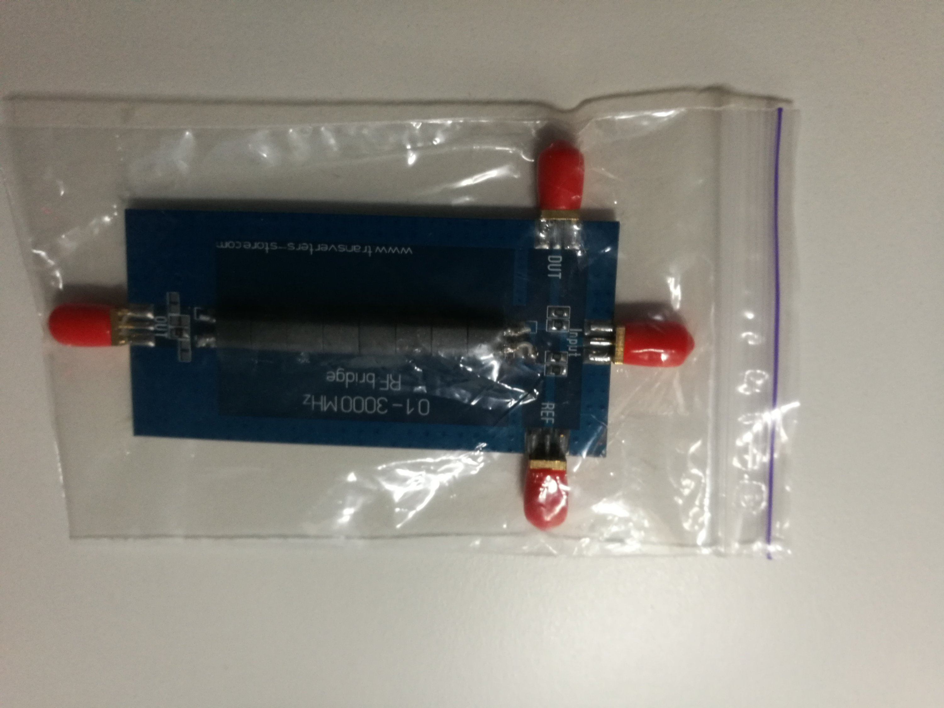
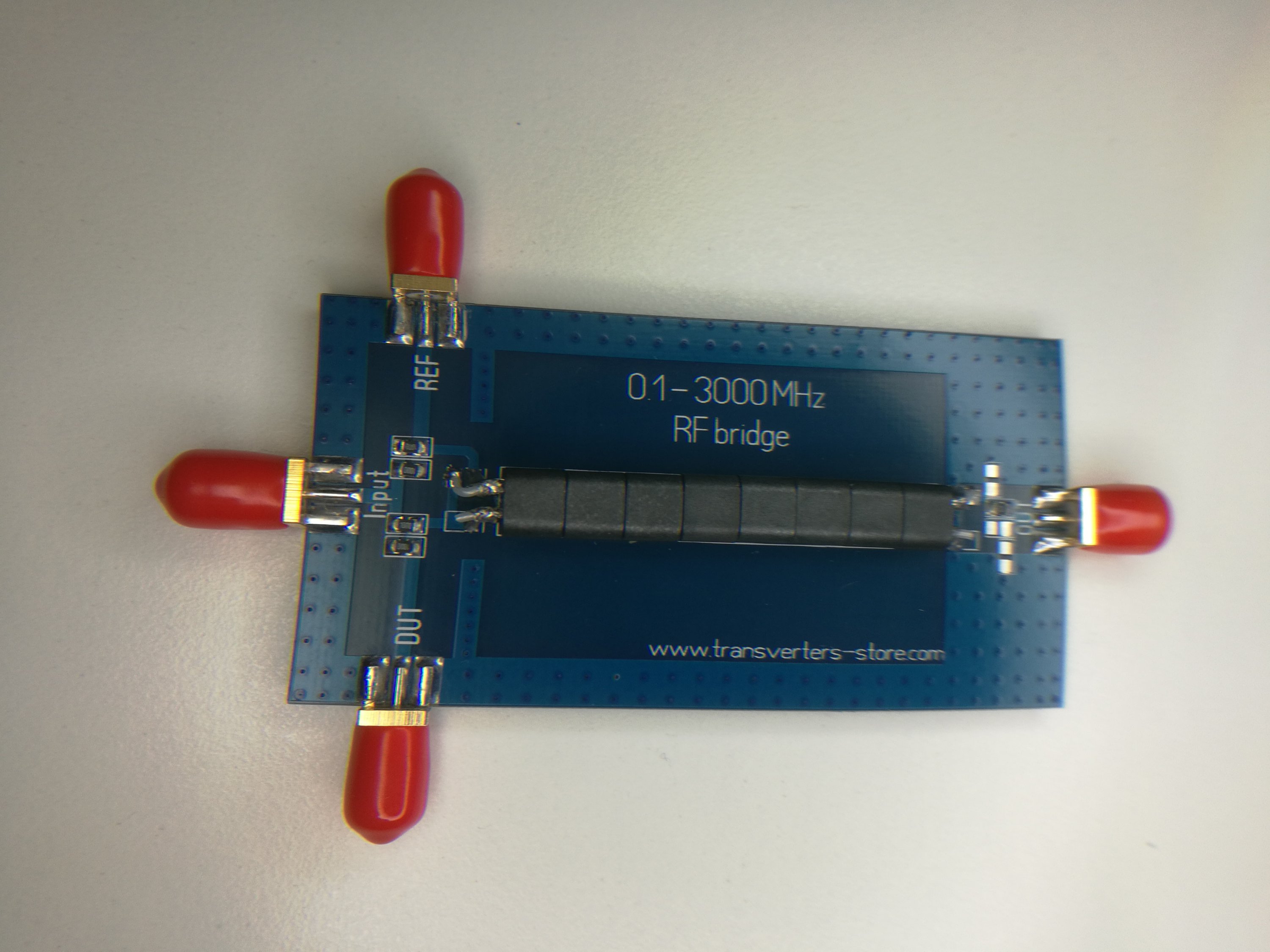
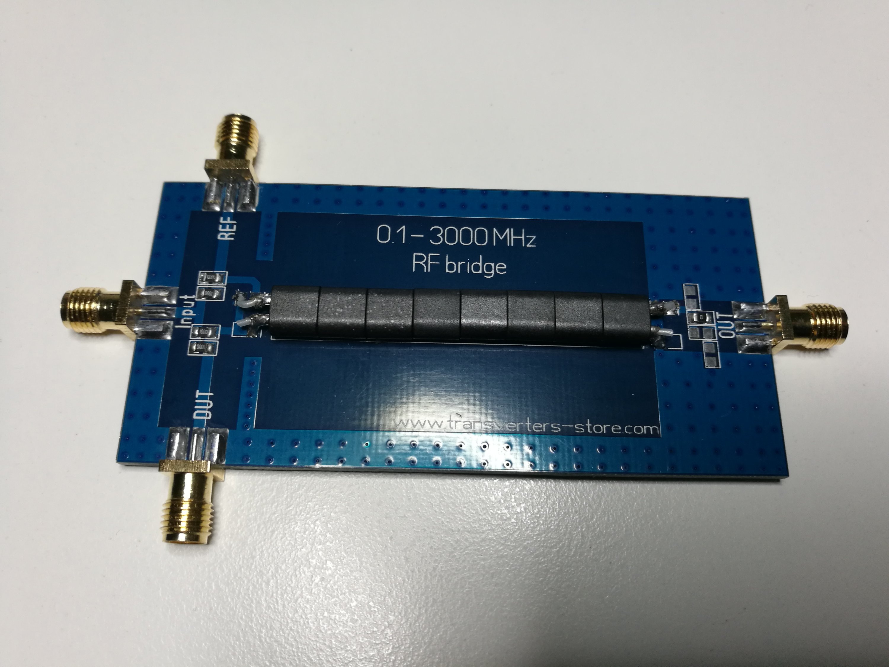
Here is the device:
Here is circuit diagram from the product page:

Here is test setup for testing a 450 MHz antenna with RF noise generator and RTL-SDR:
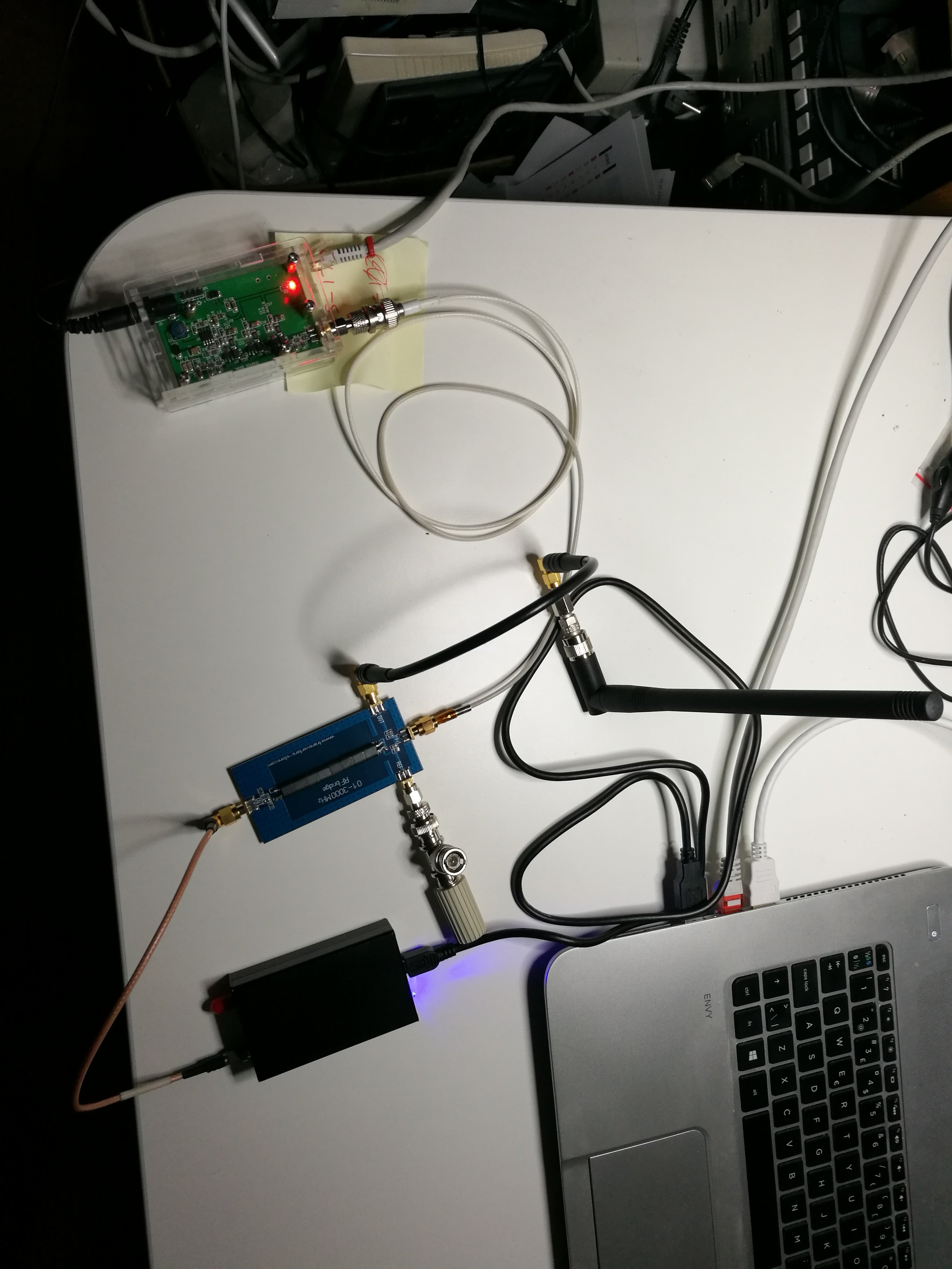
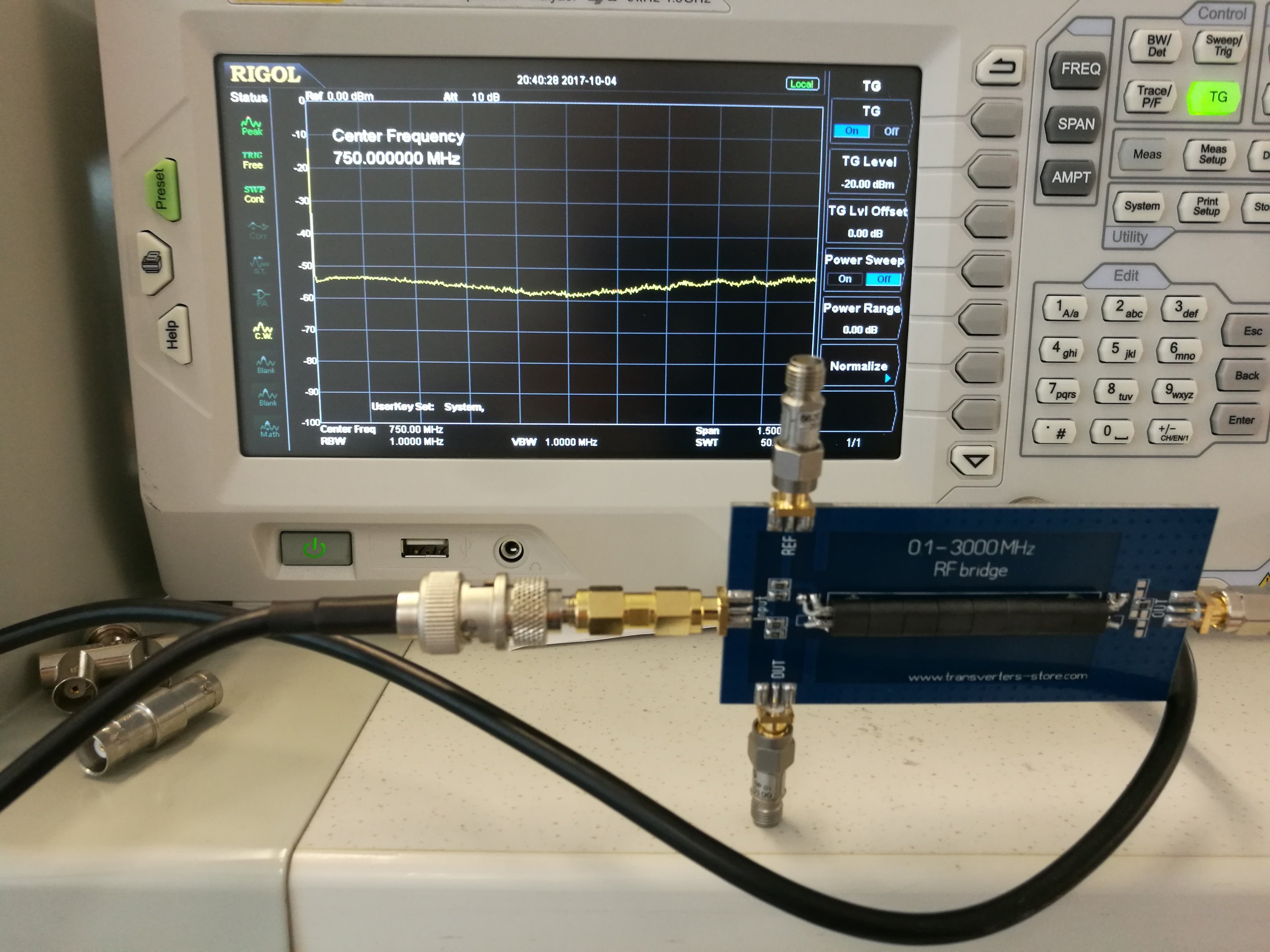
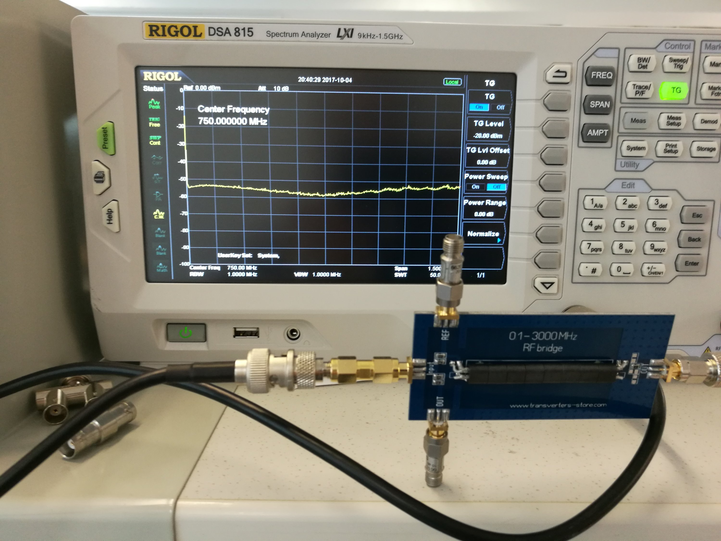
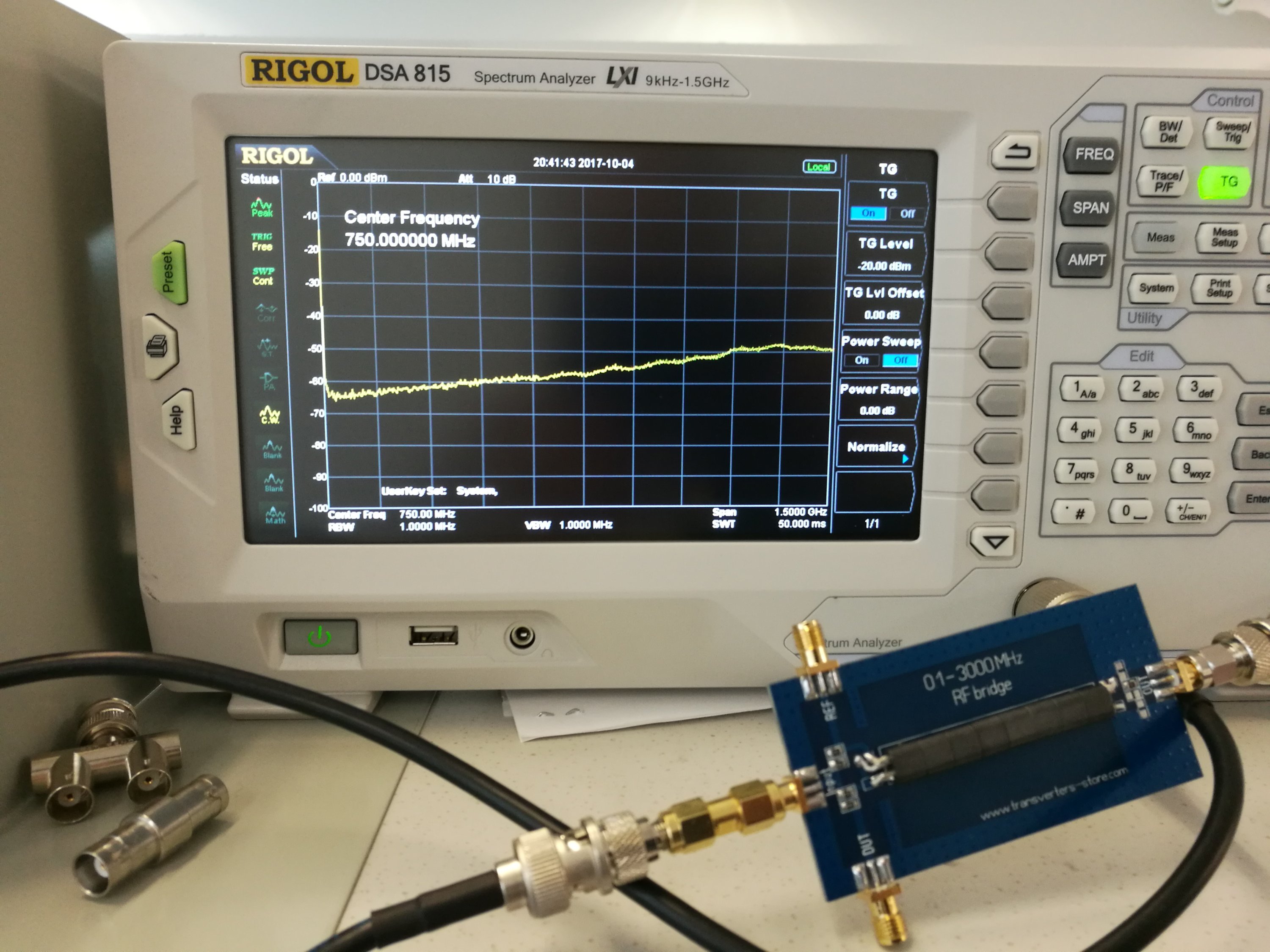
Here are two pictures: First is output terminated to 50 ohms and second with 450 MHz antenna connected to RF bridge output
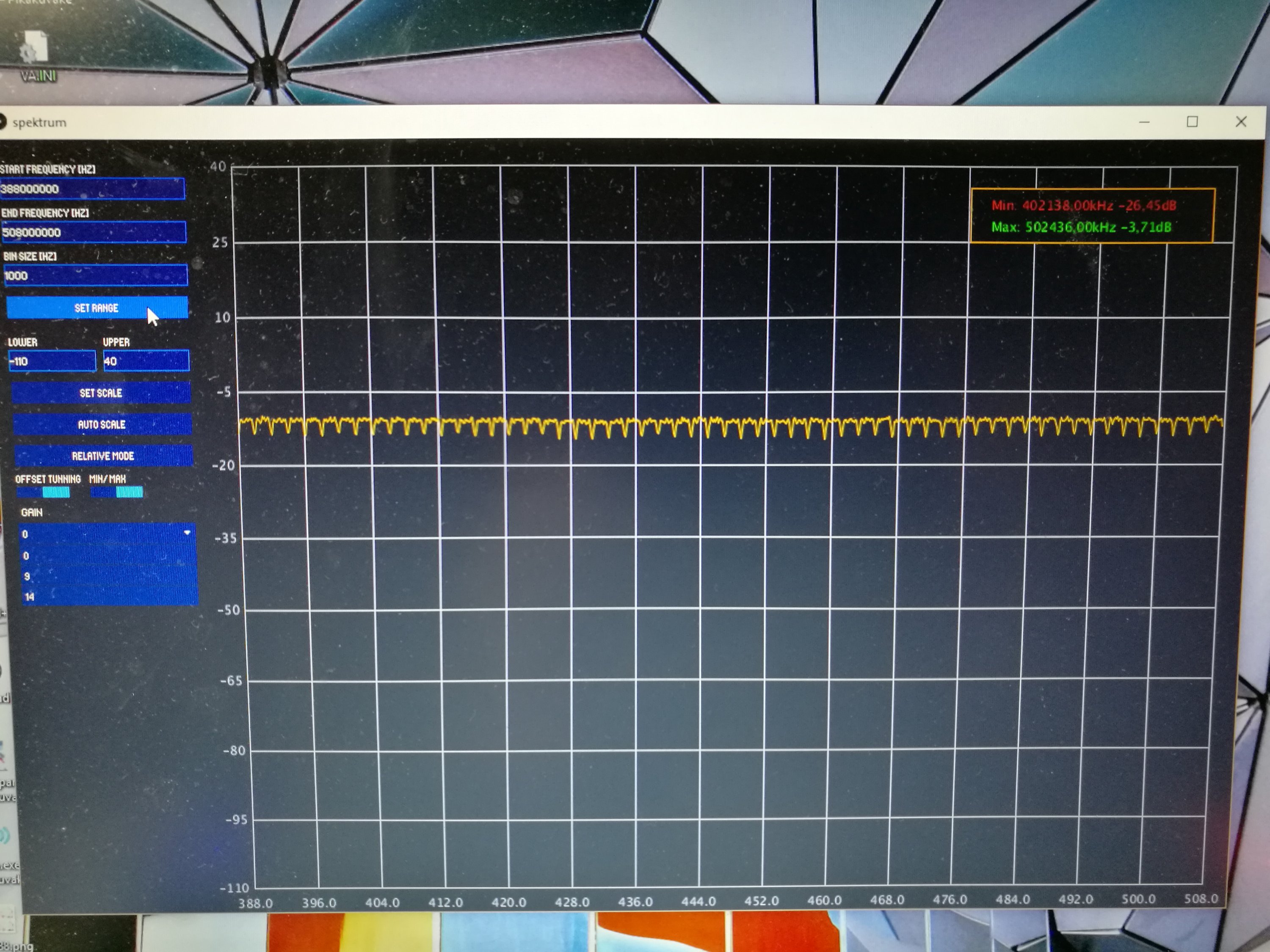
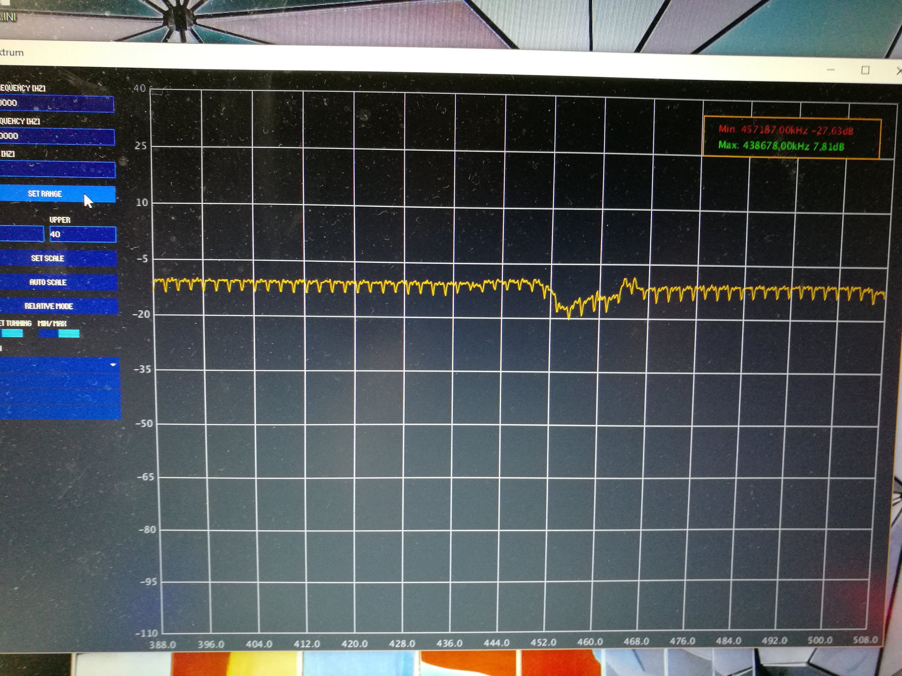
Those measurements show that this RF bridge can be used successfully for antenna measurements. It gives quite similar performance than my previous measurements with directional coupler. The advantage of this bridge is that this can be used to measure matching other impedance than just 50 ohms – just use a suitable reference against which you want to compare matching (it can be 75 ohms resistor or something mote complicated). Based on this tests the RF BRIDGE 0.1 – 3000 MHz from http://www.transverters-store.com/rf_bridge/rf_bridge.html seems to deliver what it promises.
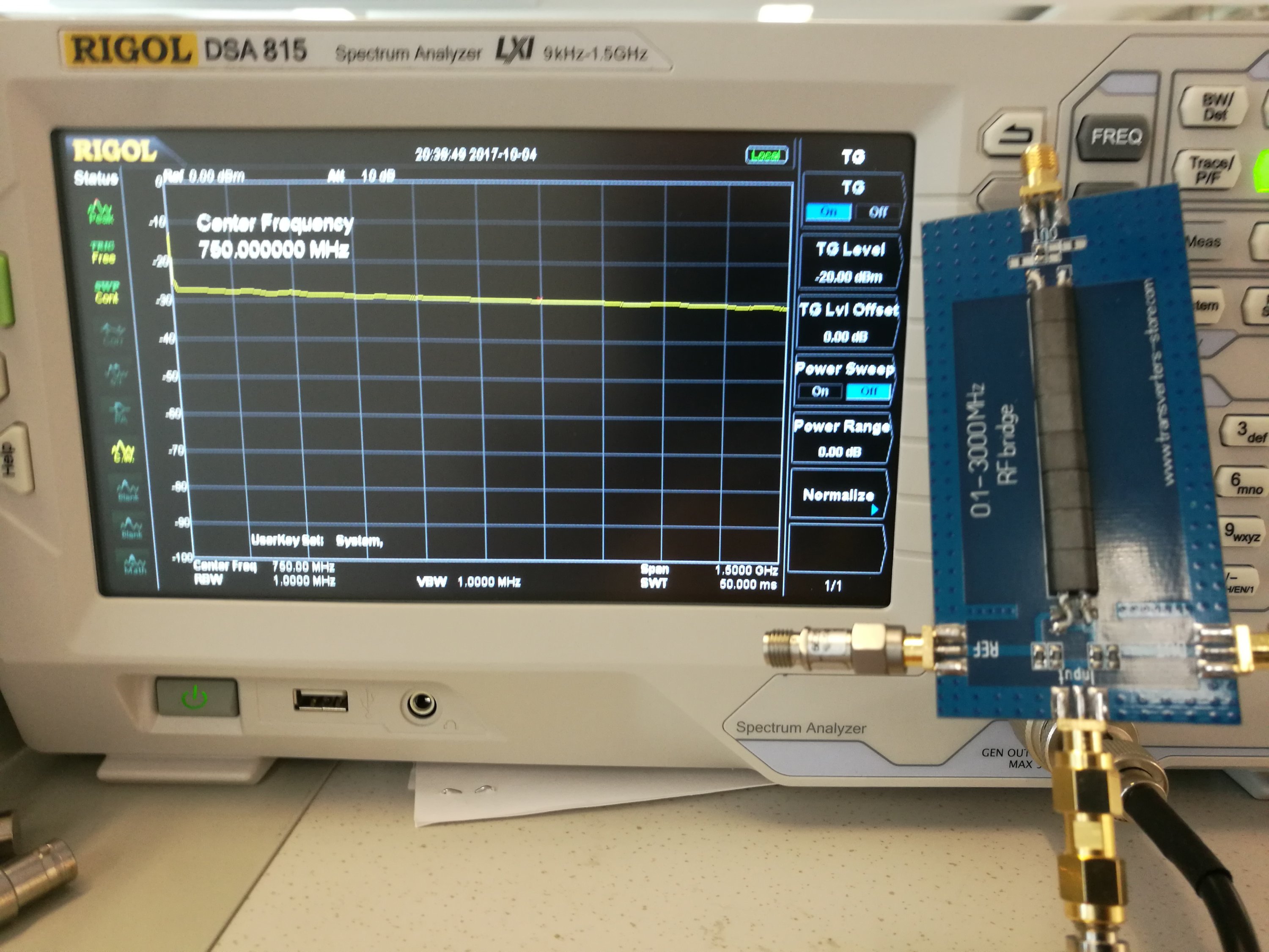
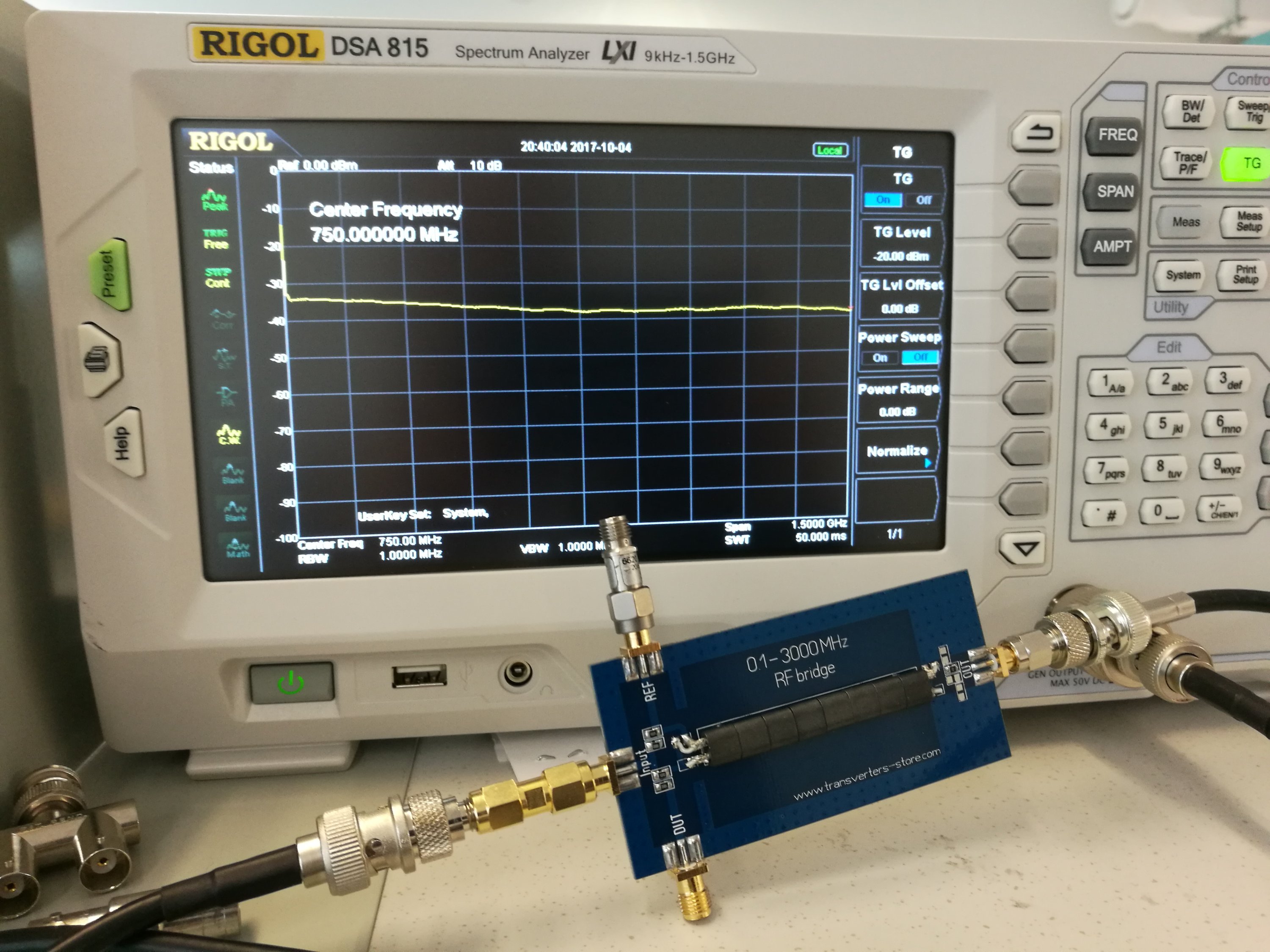
Here are some measurements on RF bridge with Rigol spectrum analyzer tracking generator up to 1.5 GHz. Those small grey adapters on the SMA connectors you see on the pictures are 10dB and 20dB 50 ohms attenuators that I use as close to 50 ohm terminator in this quick measurement…
22 Comments
Tomi Engdahl says:
$15 Ebay Return Loss Bridge
https://www.youtube.com/watch?v=ct_ZUYTRkOA
I evaluate a $15 RF Return Loss Bridge I purchased on Ebay and compare its performance against the $85 Directional Coupler I have previously been using for Return Loss tests.
Dan Nelson
4 kuukautta sitten
Hi James, I think you might want to review your DUT setup procedure, I’ve swept the ZFDC-20-5+ and a ZFDC-20-5 on my Agilent VNA and found them to be exceptionally flat, nothing like what you are showing here.
Tomi Engdahl says:
Boxed RF BRIDGE Compared
https://www.youtube.com/watch?v=lqd_6s8ZfqM
Evaluation of Ebay Boxed 500kHz-2500 MHz RF Return Loss Bridge with comparisons to the Mini-Circuits ZFDC-20-5 Direction Coupler used as a Return Loss Bridge, a $45 Boxed RLB and the $15 046 PCB bridge that I recently purchased on Ebay. Please note that the performance shown may not fully represent the capability of these RLB’s since I am not using 40dB Precision Reference loads or attenuators in this video since I do not have any available. I am using surplus Mil Spec loads however. These should provide better than 20dB return loss with most providing 25-30dB over the 0-1500 MHz frequency range of the DSA815-TG. I would recommend either of these RLBs for use below 500 MHz or so with the Boxed unit being the best performer from 500-1500 MHz. The boxed unit is available at: http://www.ebay.com/itm/121863951721 The PCB 046 unit can be found at: http://www.ebay.com/itm/332052527822
Tomi Engdahl says:
3MHz-1200MHz RF Reflection Bridge Directional VSWR SWR Bridge/Antenna Analyzer
https://www.banggood.com/3MHz-1200MHz-RF-Reflection-Bridge-Directional-VSWR-SWR-BridgeAntenna-Analyzer-p-1386844.html?p=27131452996820140438
Widely used in the antenna measurement debug, debug and test RF matching circuits. Device swept return loss measurements.
Microstrip circuit design, to meet the requirements of high frequency RF operating frequency range: 3MHz — 1200MHz.
High directivity. Typical directional 30dB and 500MHz, 27dB and 1GHz, 26dBa and 1.2GHz.
Specification:
Working frequency range: 1MHz – 1200MHz
High directivity: 1-30MHz 28dB
30-1000MHz 33dB
1000-1200MHz 27dB
Insertion loss: 13dB
Radio Frequency Interface: All three ports are SMA buses, and the general SMA buses with external threads and internal holes.
Tomi Engdahl says:
#158: Directional Coupler Basics & how to sweep SWR of an antenna | Return Loss | VSWR
https://www.youtube.com/watch?v=iBK9ZIx9YaY
This video describes the basic properties and specifications for directional couplers, and shows their basic operation on an oscilloscope. Typical applications are discussed, along with a practical example showing how to sweep the VSWR, or Return Loss, of an antenna using a directional coupler and a spectrum analyzer with a tracking generator.
D J Long says:
I bought one of these – it was useless Because:-
The pairs of 100R resistors where not connected together; The wring of the cables through the ferrite was wrong.
Tomi Engdahl says:
The I received worked and seemed to be built so that it matches the circuit diagram pretty closely.
The major difference is that that on OUT there is no attenuation resistors, just one 0 ohm resistor.
The 100 ohms resistors were wired as in circuit diagram.
The wiring through ferrites match the circuit diagram?
Do you mean your product was baddly build? (they need better quality control)
Or do you think that the original design as shown in the circuit diagram is flawed?
Tomi Engdahl says:
https://m.banggood.com/RF-SWR-Bridge-0_1-3000MHz-Return-Loss-Bridge-Reflection-Bridge-Antenna-Analyzer-VHF-VSWR-Return-Loss-p-1497170.html?akmClientCountry=FI&rmmds=search
Allan Wright says:
It looks like the link that you posted from banggood.com is for a counterfeit Chinese copy of the original bridge from the Ukraine. I recently bought one of the genuine ones from the designer’s website at http://www.transverters-store.com and the build quality is excellent, far superior to the counterfeit one. He discusses the issue of counterfeits on his website. I would encourage anyone wanting one of these devices to go to http://www.transverters-store.com and spend the extra few dollars for the genuine unit.
Alan VK2ZIW says:
I bought four from AliExpress, luckily one of them was a genuine one.
As mentioned above, there is two missing tracks joining the 100 ohm resistors.
A multimeter should show 25 ohms on the IN port. The REF and DUT should measure short.
When fixed the Chinese copies work but performance beyond 1300MHz is useless.
Also the bridge that came with the “Simple Spectrum Analyser & TG” marked 5 – 500 MHz
suffers from too much capacitance in the little transformer limiting it’s useful range to 5 – 100 MHz.
Obviously nobody actually tests anything. I wanted something for 2.4GHz.
neil says:
hi
having just bought the same device i have found some comments about the circuits not being wired correctly im interested in your results and diagrams, the circuit you show has several resistors near the output and like mine theres non on the actual board ?
mine also had the balanced line inner and outer connected and the output line is a near short to earth, yours being wired to the same points makes me think yours is similar.
now i did get a similar reading on the spectrum returns but dont believe its a true return loss
check out this page for a similar circuit
http://www.dicks-website.eu/return%20loss%20bridge_part1/part1.html
best regards
Tomi Engdahl says:
Return loss bridge. (part 1)
http://www.dicks-website.eu/return%20loss%20bridge_part1/part1.html
Circuit diagram of the return loss bridge.
Tomi Engdahl says:
Use this kit to test #antennas for your #wireless and #IoT products #review #VNA https://buff.ly/2DUbrqI
Tomi Engdahl says:
https://www.changpuak.ch/electronics/DIY-DualDirectionalCoupler.php
Tomi Engdahl says:
And original is shipped from Ukraine https://www.ebay.com/itm/ORIGINAL-RF-SWR-Reflection-Bridge-0-1-3000-MHZ-Antenna-Analyzer-VHF-UHF-VSWR-/292083525131
Tomi Engdahl says:
Some of the clones were improperly wired on the OUT side. You need two TinySA to make a measurement. One to output the signal and the other to receive the signal.
You can also use one TinySa to measure and a noise source or RF generator. This will only work as a scalar analyzer and not as a vector analyzer so you can only measure SWR, Return Loss and impedance magnitude.
You need to calibrate using short, open and 50 ohm loads. Accuracy will be worse than a NanoVNA.
Tomi Engdahl says:
From https://m.facebook.com/groups/368777730463838/permalink/642289483112660/
If you got bridge from China 99,9% chance it is a fake and not working due to serious errors in copying and bad ferrites. Luckily for you, errors can be easily fixed, but for 3GHz operation you´ll still have to replace coaxial cables with UT-141 rigid or something similar and replace ferrites with better. Fixed chinese fake can be used up to 1GHz.
Tomi Engdahl says:
Original store product page
https://transverters-store.com/rf_bridge/rf_bridge.html
Tomi Engdahl says:
This looks like an alternative:
10-3000MHz Standing Wave Ratio Reflection Bridge SWR RF Directional Bridge Network Circuit Antenna Ham Radio Amplifier
https://www.banggood.com/10-3000MHz-Standing-Wave-Ratio-Reflection-Bridge-SWR-RF-Directional-Bridge-Network-Circuit-Antenna-Ham-Radio-Amplifier-p-1789895.html?currency=EUR&utm_source=criteo&utm_medium=cpc_brand&utm_content=all&utm_campaign=electronics-emea-en&cur_warehouse=CN
Model: Standing wave bridge
Frequency range: 1MHz ~ 3GHz (1MHZ-2.6GHZ is relatively flat)
Characteristic impedance: 50Ω
Directionality: ≥30dB
Maximum input power: ≤0.2W
Tomi Engdahl says:
1.8M-30MHz 3.5-30MHz SWR Bridge RF SWR Reflection Bridge For RF Network – Finished board
https://www.banggood.com/1_8M-30MHz-3_5-30MHz-SWR-Bridge-RF-SWR-Reflection-Bridge-For-RF-Network-p-1881641.html?currency=EUR&utm_source=criteo&utm_medium=cpc_brand&utm_content=all&utm_campaign=electronics-emea-en&cur_warehouse=CN&ID=6303183
Specification:
- Condition: 100% brand new and high quality
- Item Name: SWR Bridge
- Color: as shown
- Frequency: spare parts: 1.8M-30MHz; finished product: 3.5-30MHz (default)
- Size: 45mmX 29mm
- Type:
A: DIY Kit (optional)
B: Finished board
Tomi Engdahl says:
1.8M-30MHz 3.5-30MHz SWR Bridge RF SWR Reflection Bridge For RF Network – DIY Kit
https://www.banggood.com/1_8M-30MHz-3_5-30MHz-SWR-Bridge-RF-SWR-Reflection-Bridge-For-RF-Network-p-1881641.html?currency=EUR&utm_source=criteo&utm_medium=cpc_brand&utm_content=all&utm_campaign=electronics-emea-en&cur_warehouse=CN&ID=6311493
Tomi Engdahl says:
https://www.makeuseof.com/tag/how-to-make-a-wifi-antenna-out-of-a-pringles-can-nb/
Tomi Engdahl says:
Log‑Periodic Dipole Array Calculator
https://hamwaves.com/lpda/en/index.html