Light Dimmers are devices used to lower the brightness of a light. Light dimmers are generally used to control light output from resistive incandescent, halogen, and sometimes also compact fluorescent lights (CFLs) and light-emitting diodes (LEDs). Dimming LEDs have their own set of challenges and dilemmas. Modern dimmers are built from semiconductors that are often controlled with micro-controllers and other digital circuit. Those digital dimming circuits typically need information on mains power timing to work correctly. Here is where zero-cross detection circuits are needed. They come in many forms. I have described some ideas on my Four channel dimmer rack and Light dimmer circuits documents.
This article deals with potentially dangerous topics, so a little warning here: Mains voltage can be lethal. This applies both 110V AC and 230V AC and other popular voltages. Direct connection to mains wiring can be tricky, and dangerous. Know for sure what you are doing and be very careful! This article gives some ideas, and there is no guarantee that all the ideas are correct or safe.
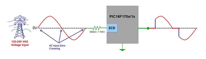
In applications where there is no need for safety isolation from mains power, zeros cross detection could be in simplest case implemented by feeding mains voltage through suitable high resistance resistor to suitable micro-controller input pin. For example this Microchip offers this block diagram of the idea:
Elprojects article 220V zero crossing detection using AVR microcontroller with minimum components this image taken from Atmel application note AVR182:

This circuit might look a bit strange, because this idea is basically feeding high voltage mains to micro-controller input pin through just one resistor. But it should be safe, because 230 AC through 1M ohm resistor, being fed directly to the AVR microcontroller will not do any harm to it. This is because this micro-controller has an internal clamping diodes that limits the high input voltage to micro-controllers operating voltage as long as the current is kept at reasonable range (and here 1Mohm resistor does that).
But what if you want safety isolation from mains power? Things get somewhat more complicated. On my Four channel dimmer rack circuit I used method, where I did the zero-cross detection on the low voltage signal from mains power transformer (here you get short 10V pulses from Q1 collector at every main zero cross).
But what if you don’t want to use transformer for this isolation task? Then the next idea is to use opto-isolator where you drive the input LED with mains power through suitable resistor… Like for example in this circuit from AVRFREAKS detecting zero-crossing discussion:

The the basic idea is good. You rectify the mains power, and then feed the power through resistors to opto-coupler. This simple circuit has a big down-side that is power loss: that schematic with two 22K resistors, you will have 1.1W dissipation only on those two resistors. There is another more severe potentially problem on the circuit design: the specified W005G bridge rectifier is rated for only 50V, while it is connected here to 230V mains voltage! A huge oveload on voltage so it will fail sooner or later dangerously.
I was looking for a lower power and otherwise improved circuit idea. After some searching I found two interesting looking circuits for low power isolated mains power zero-cross detection: Mains-driven zero-crossing detector uses only a few high-voltage parts published in EDN magazine and DIY – Isolated High Quality Mains Voltage Zero Crossing Detector circuit from Dexrel. Both of those circuits use pretty much similar ideas for low power zero-cross detection. From those circuits I decided to test this DIY – Isolated High Quality Mains Voltage Zero Crossing Detector circuit because it looked a bit simpler and consumed less power.

This circuit promises ultra-low power consumption; worst case power dissipation < 120mW. The circuit promised to produce constant and well defined zero crossing pulses, centered symmertically around the zero crossings, with pulse length is virtually independent of the mains voltage. In addition to that the circuit promises using very little power and just a few plain vanilla components: The circuit design is nice such that only resistors R1 and R2 and opto-isolator need to be designed to withstand mains voltage, all other parts can be low-voltage normal components.
I built the circuit prototype to a solderless breadboard:
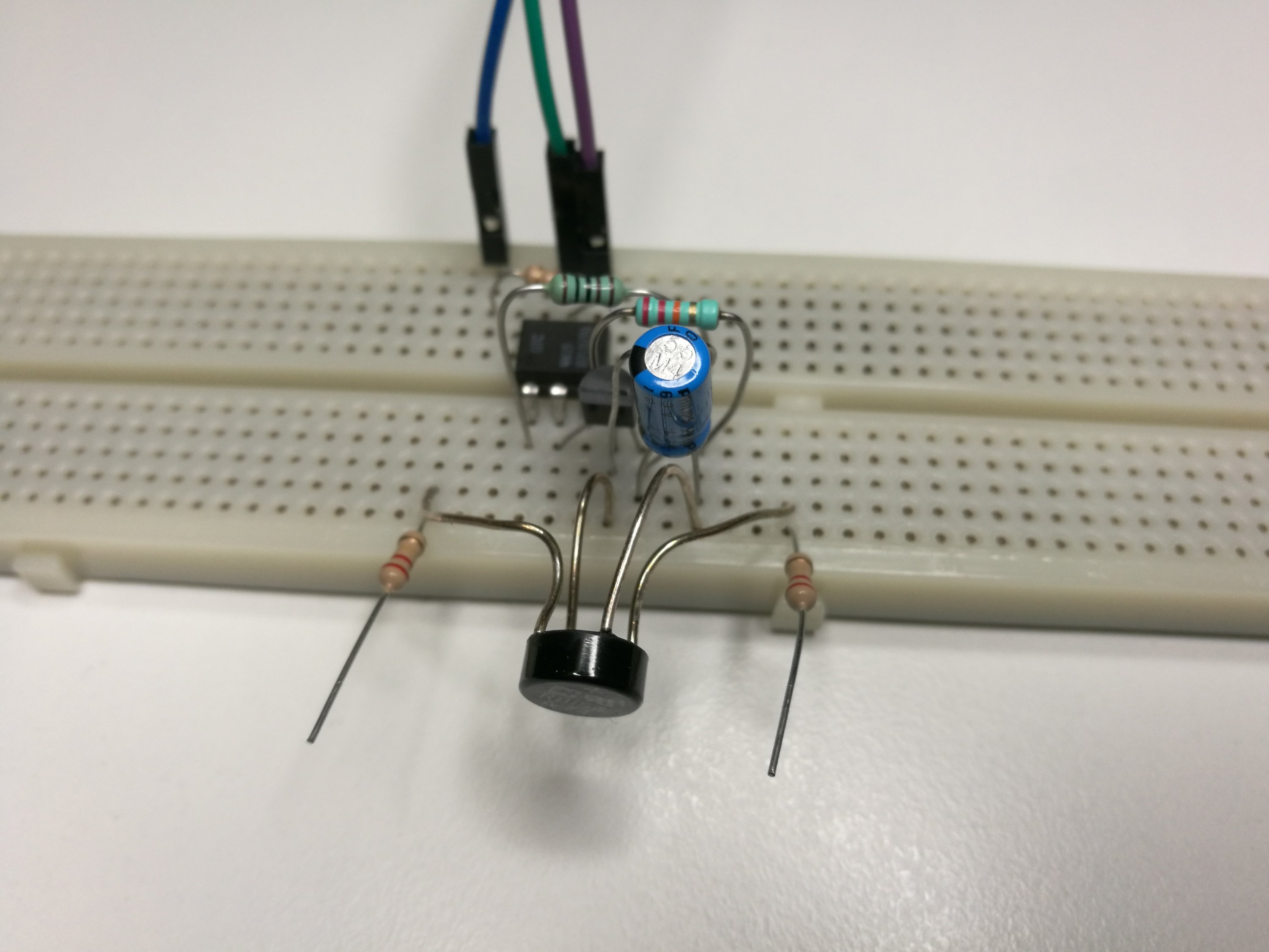
I first tried the circuit at safer lower voltage (12V AC with lowered R1 and R2 values). Then I tried the circuit with full 230V mains power from safety isolation transformer. The circuit worked as expected. The typical pulse width is 1ms at 50Hz. Please note that it is not generally a good idea to try to build any mains voltage circuit to a breadboard because they are generally designed to be used with low voltage circuits only.
Circuit operation: The zero crossing circuit consists of the voltage to current converting resistors R1-R2, full-wave rectifier diodes D1-D4, a voltage averaging and storing capacitor C1, the opto-coupler U1, and transistor Q1 that functions as a voltage comparator. Transistor Q1 stays off during the majority of the mains cycle, during which C1 is charged. Q1 turns on and feeds current from C1 to the opto via R4, whenever the mains voltage (divided by (R1+R2)/R3) is lower than the voltage across C1.
2 Comments
Rob says:
Hi – You are using and showing a Bridge rectifier rated at 50V for the 230V input – and the resistors are on the input on the breadboard before the bridge – but after it on the circuit… Even with an isolating transformer, 230V on a breadboard is not advisable! When we look at a breadboard, we typically think “low voltage – can poke about”…
Tomi Engdahl says:
You are right on that rectifier issue.
I did not spot that when picked the circuit idea. Not good at all. I have to add note on that.
You are right that generally mains voltage at breadboard is not a good idea, but can work sometimes of you know what you are doing.