Years ago you had to either build your own signal generator or buy usually a quite expensive signal generator. Lately there has been a push for very cheap ($15-25) digital function generator kits available from China. I wrote about some interesting function generator devices few years ago, and here is a closer look to one such function generator.
Some time ago I received DDS Function Signal Generator Module Sine Square Sawtooth Wave Signal generator. It is just a circuit board with components and no case type module. This product is a generic type that can be found from a variety of the usual online stockists. It takes the form of a PCB about 100 mm by 80 mm with one of the ubiquitous alphanumeric display modules atop it, and a couple of BNC sockets for output.
Some generic similar products come with no name printed to them, the device I got has GeekTeches FG-050 brand and model name printed to circuit board. I just put it into the case I happened to have to get this kind of device a result.
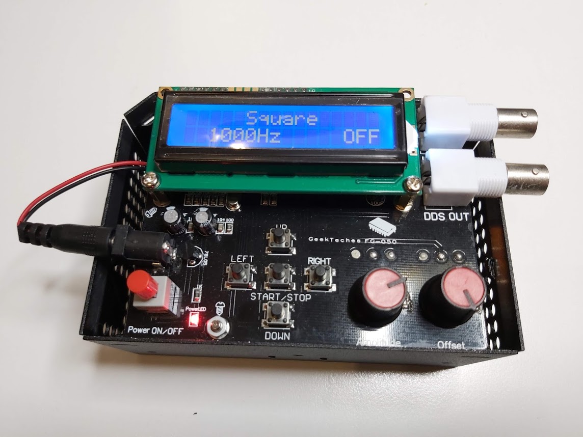
This is a function (waveform) signal generator designed with 1602 LCD screen and 5 buttons user interface. It can promises to produce many often used periodic time function waveform (sine, square, triangle, sawtooth, and pulse wave, etc.) where you can adjust frequency, amplitude and DC offset. The frequency range is 1HZ-65534Hz controlled with buttons. The amplitude and DC offset amount are adjusted with two potentiometers. The signal output is BNC connector. In addition to those analogue signals, this signal generator can generate 1-8 HHz square wave signal.
Buttons Functions:
UP: Output waveform select
DOWN: Output waveform select
LEFT: Output frequency -
RIGHT: Output frequency +
START/STOP: Output stop / start
Select the desired waveform with the UP and DOWN buttons and the desired frequency with the LEFT and RIGHT buttons. With LEFT you reduce the frequency, with RIGHT you increase this quantity. It is a good idea to ‘Frequency Step’ (1 Hz, 10 Hz, 100 Hz, 1 kHz and 10 kHz) first so each LEFT/RIGHT control changes the frequency some sensible amount. Finally, press the START/STOP button until ‘ON’ appears on the display so you get the signal from BNC output. When signal output is on, user can’t change the signal parameters. Ti make any changes to signal with the buttons, output needs to be turned off first.
After switching on the unit, the output goes to the last set parameters, which is a good feature.
Operating voltage: DC7V-9V
Size: Approx. 100*80mm (Length*width)
Template thickness: 2mm
DDS frequency range: 1HZ-65534Hz.
High-speed frequency (HS) Square Wave: 1MHz/2MHz/4MHz/8MHz
DDS signals: sine wave, square wave, sawtooth, reverse sawtooth, triangle wave, ECG wave and noise wave
Section into the Value: 1,10,100,1000,10000 Hz
Offset: 0.5pp-5Vpp
Amplitude amount: 0.5Vpp-14Vpp
Output impedance: 20-200 ohms
Color of PCB: black and blue random delivery
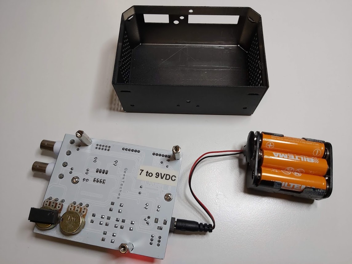
For power there is a 2.1 mm barrel jack through which it will accept 7 V to 9 V DC with centre pin to as positive. I powered my function generator with 9V DC that comes from six AA batteries.
Here is the video (not made by me) of the function generator:
Here is view to the back side of circuit board:
This digital function generator is a typical low frequency signal source. This circuit works very well simple signal generator for example for audio signal tracing through a circuit. Basically this generator does exactly what it claims. From its 1 Hz lower end to its 65.5 kHz upper end, the sine wave shape remains the same and the amplitude and offset I selected on the two potentiometers is consistent. The other waveforms are the same, square, triangle, sawtooth, random noise, ECG waveform.
It is a quite capable little function generator, it’s not quite a perfect function generator. There are few limitations on the circuit and implementation:
Signal waveform is no always perfect and setting the signal parameters accurately is not easiest. You need to use the buttons to select the waveform and frequency and then use potentiometers to set amplitude + offset. The waveform and frequency can be adjusted only when signal output is off. There is no continuous frequency adjusting potentiometer like in many analogue function generators.
At the higher frequencies its sample step becomes visible on the ‘scope, but most annoyingly in operation, the potentiometers lack a fine control. So getting the amplitude and offset right on the mark can be a frustrating process if you have accurate needs. A simple potentiometer is not usally very useful for practical applications in the lab.
With incorrect potentiometer settings you get easily distorted signal. FG-050 reproduces a 1 kHz sine wave without problems and visible distortion. However, if you set the amplitude potentiometer to the maximum value, the signal get stuck against a positive threshold of +8.0 V and a negative threshold of -6.9 V. Setting a DC offset at this value of the output voltage makes no sense at all.
If you turn the potentiometer of the FG-050 back so far that the generator delivers a voltage of 100 mV, but the 1 kHz sine wave is completely distorted by remnants of the microcontroller’s clock signal. If you need low level signals, it is a good idea to connect a 1/10 or even 1/100 resistance divider to the output.
When reading on the specifications, you can notice that the output impedance not 50 ohms as many better signal generators have. The output impedance was not very clearly defined, so I did some testing. I found out that the output impedance was very low (few ohms) at low signal levels. When I added 50 ohm load to output, the output signal did not change noticeably at some cases, and on some other test cases adding that load distorted the signal very much.
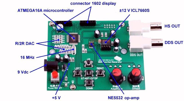
To the circuit operation next. Chinese electronics products tested page has a nice overview of what is in the circuit board:
Chinese electronics products tested page also provided a nice circuit diagram:
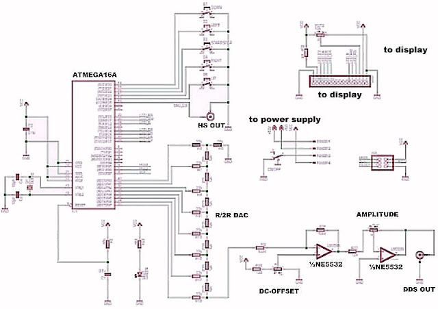
Circuit diagram of DDS generator is very simple using AVR Atmega16 micro-controller clocked with 16MHz, standard HD44780-based 2×16 LCD module, R2R DAC made of simple resistors and NE5532 dual op amplifier output buffer. NE5532 dual op amplifier output buffer implements DC offset and amplitude adjusting circuits. The output is driven directly from NE5532 output pin. This output gives quite clean and low impedance output if the output is not overloaded. With high impedance loads (few kilo-ohms or more) I could get up to 5.4 V RMS with sine-wave signal without noticeable distortion. If you are driving low impedance loads, there is limitations. On my tests the output was able to drive only up to around 700 mV RMS sine-wave to 50 ohms load before distortion to the signal.
The NE5532 is a high-performance operational amplifier with Unity-Gain Bandwidth of 10 MHz, low distortion and output short-circuit protection. The output impedance is typically just 0.3 ohms (@10 kHz RL=600 ohms). Output short circuit current is typically 38 mA (10-60 mA). The NE5532 is powered with +- power supply. The negative voltage from +7-9V DC is made with an ICL7660 switched-capacitor voltage doubler chip.
All the signals are generated using software running at AVR microcontroller that is powered with 5V regulator. The output frequency limitations of the DDS output are probably limited by the software speed and bandwidth limitations of output operational amplifiers.
ATmega16A is 8-bit Microcontroller with following characteristics:
16KBytes of In-System Self-programmable Flash program memory̶
512Bytes EEPROM
1KByte Internal SRAM
Operating Voltages 2.7 – 5.5V
Speed Grades 0 – 16MHz
That ATmega16A can be viewed as the little cousin of the ATmega328 used in popular Arduino Uno development board. There many signal generator designs that use ATmega328, but this board has decided just to do the same with less expensive controller.
The DDS output signal is generated with software running on the ATmega16A. The output signal is driven to eight output pins and the result is converted to analogue signal with 8-bit R2R ladder DAC circuit.
The quality of the output signal is determines with the accuracy of the resistors used in the DAC circuit. On a printed circuit board, using discrete components, resistors of 1% accuracy would suffice for a 5-bit circuit and for for 8 bits, the accuracy required will be better than 1/256 (0.4%) to guarantee monotonicity of output at least on the most significant bits. Resistors used with the more significant bits must be proportionally more accurate than those used with the less significant bits. I do not know or I have not measured the accuracy of the resistors used in this board, but based on waveform on the oscilloscope screen the quality looked decent.
There is also a second output, HS OUT, where only rectangular High Speed signals appear with four fixed frequencies up to 8 MHz. The High speed (HS) signal is direct output from Atmega16 OC1A(PD5) pin. When not loaded, it is 5V TTL level signal. When I added a 50 ohms load, the high level voltage dropped to around 3.3V.
Other reviews of similar devices:
https://chinese-electronics-products-tested.blogspot.com/p/fg-050-function-generator-tested.html
https://hackaday.com/2020/02/25/review-unnamed-chinese-dds-function-generator/
https://www.epanorama.net/blog/2015/09/15/interesting-signal-generators/
2 Comments
Dakota Ingram says:
Wow, looks great, especially the end. I was searching for that subject for a couple of days
across the nest, however there was nothing precious.
So pleased to reach your post at the end. I’m excited about this subject, and I need
to be always conscious of the latest news. That is a joy to see your post and finally clarify the issue myself.
Tomi Engdahl says:
Help!!! My Electronics Project Doesn’t Work… AGAIN! 10KHz – 255MHz RF Signal Generator
https://www.youtube.com/watch?v=a5MNlbG8eRw&t=0s
Build A Low Cost 10KHz-255MHz RF Signal Generator Project – Part 2
https://www.youtube.com/watch?v=btsEM8XNmuk&t=1879s