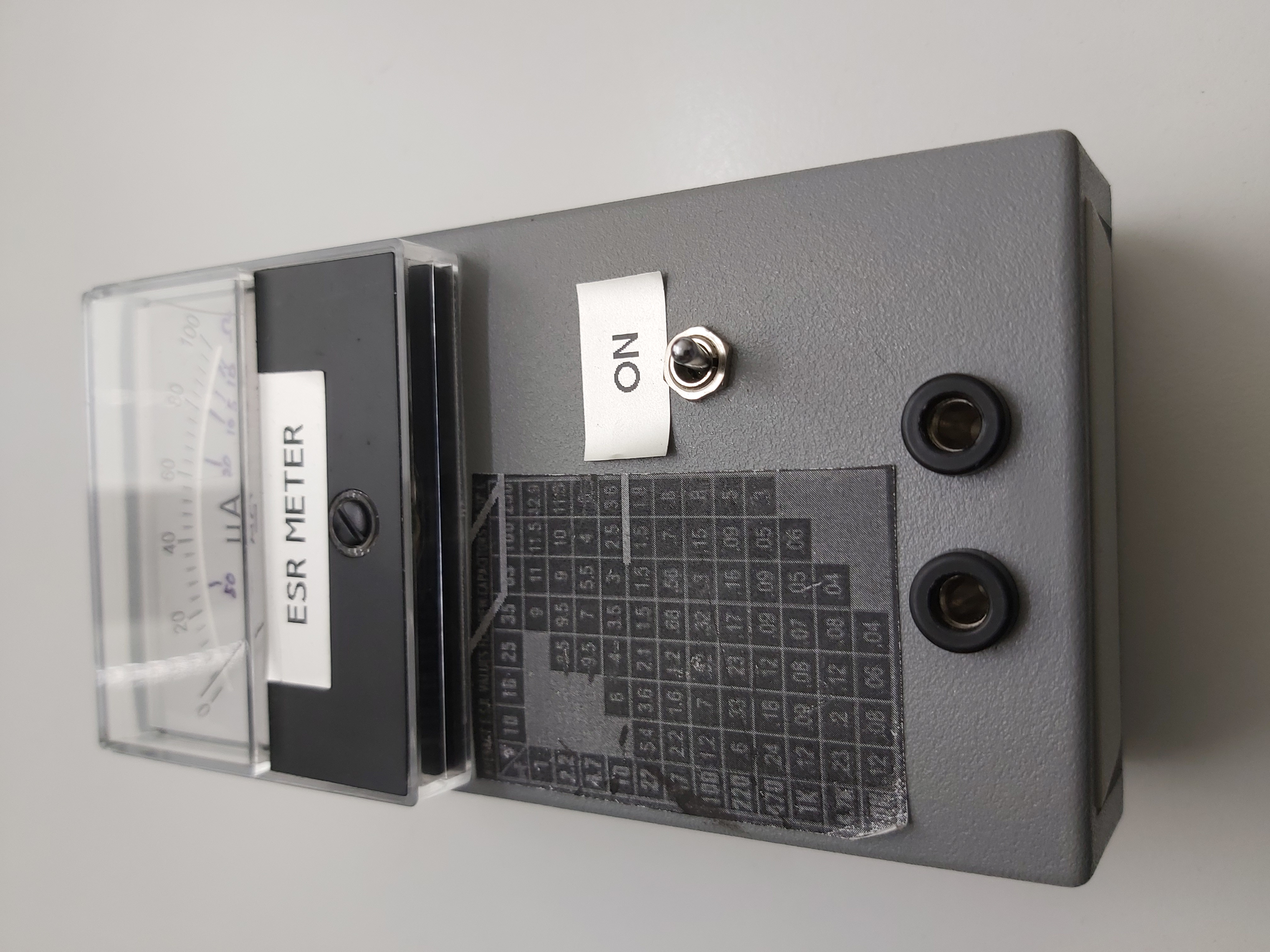
One way to test electrolytic capacitors is to measure their capacitance. It does not tell the whole story of capacitor condition. Another usually more useful way to measure electrolytic capacitor condition is to use an ESR meter. Here is ESR meter I built years ago based on instructions from http://ludens.cl/Electron/esr/esr.html
but I built the transformer differently from parts I had (took toroidal inductor and wound extra coil).
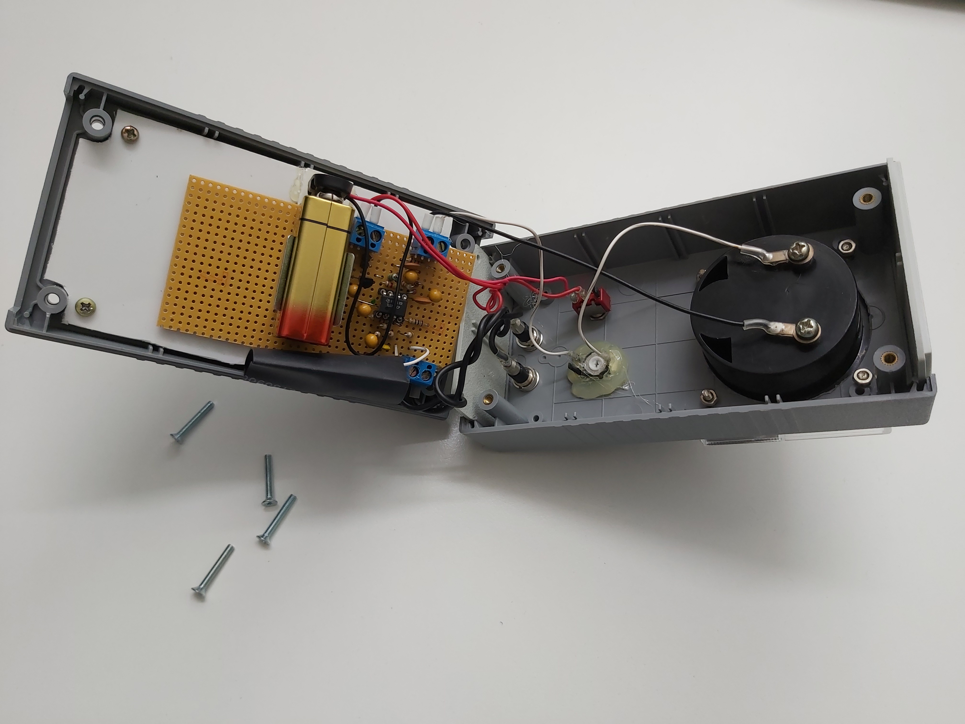
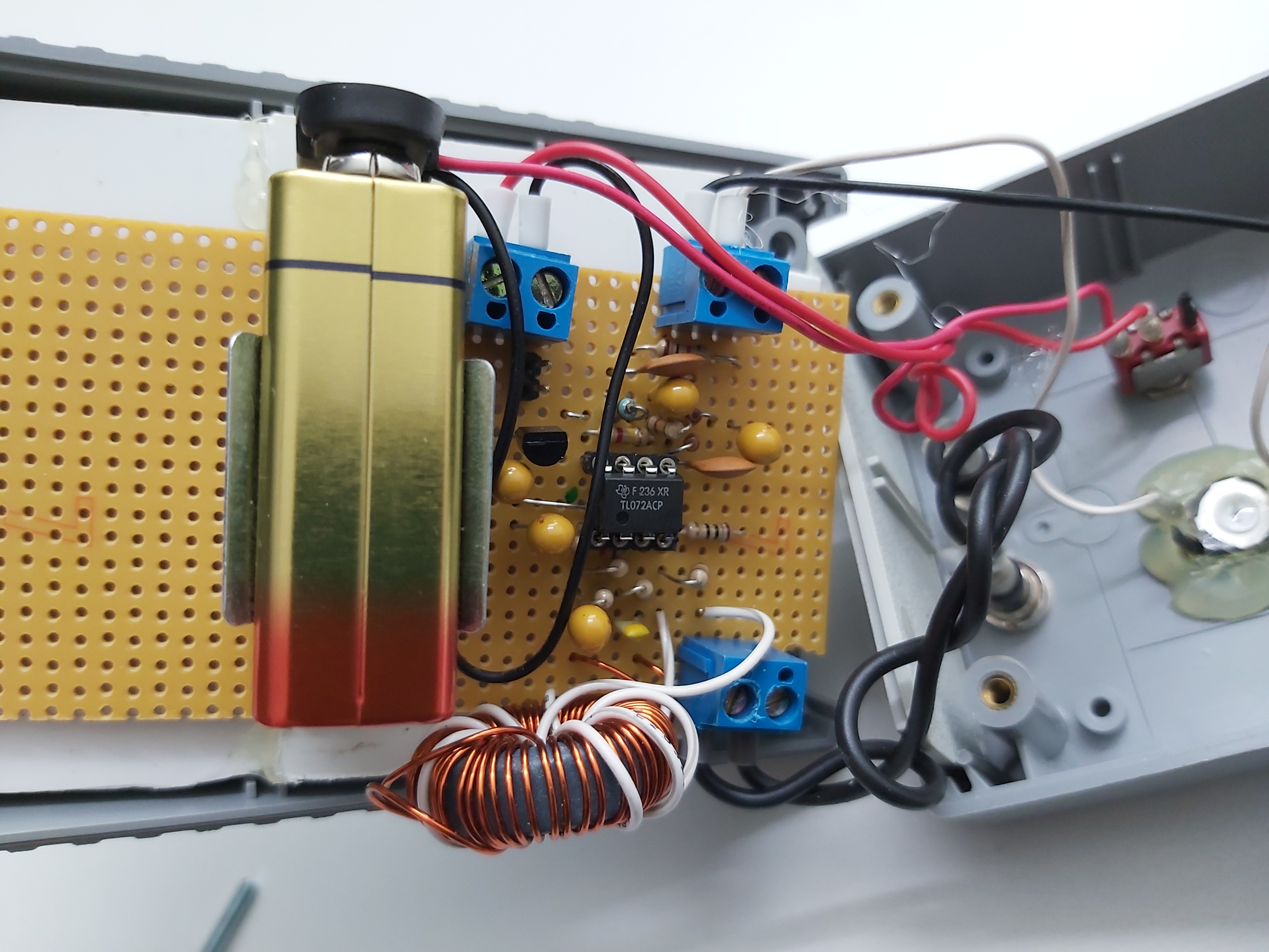
Inside
Circuit diagram
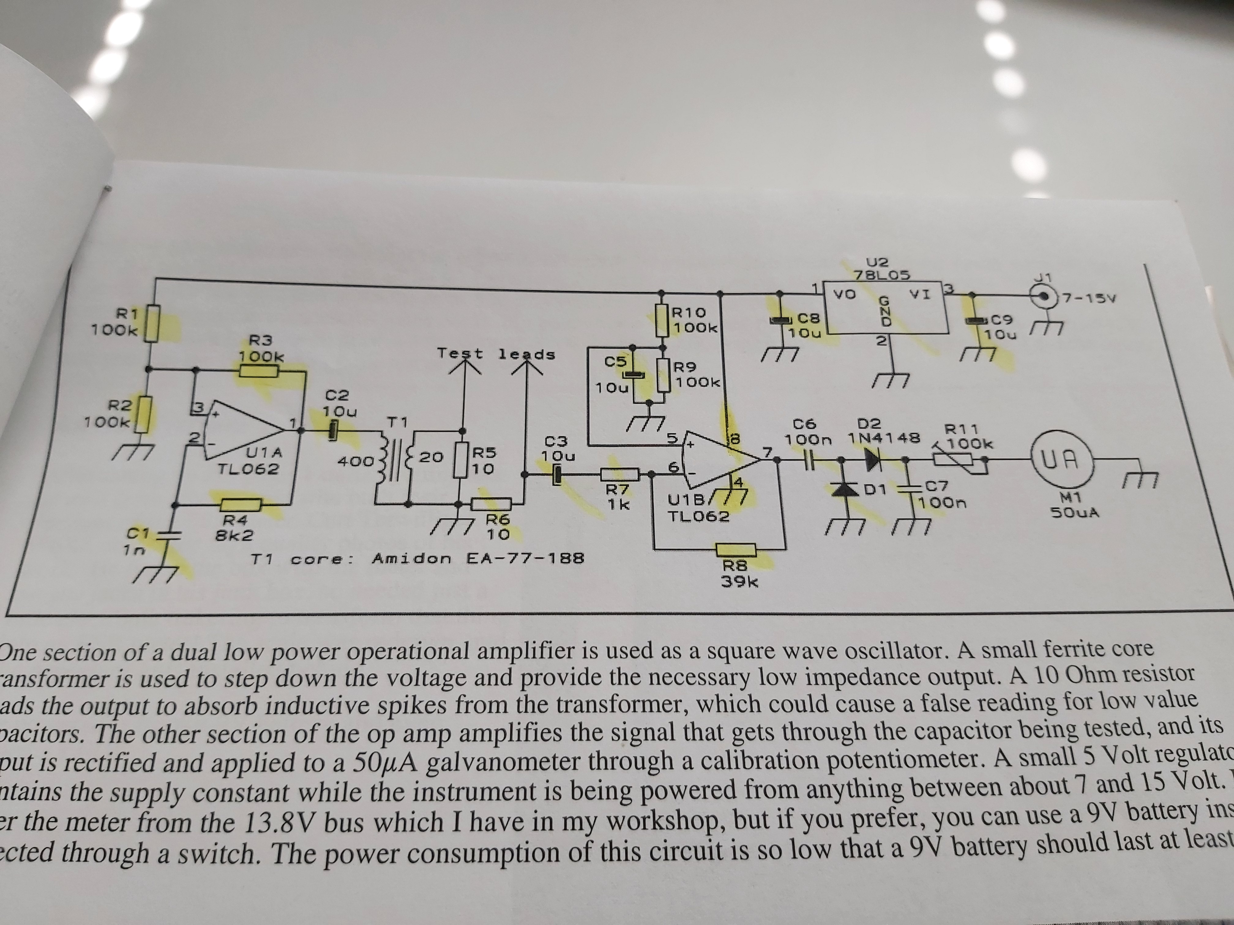
The design presented here works by applying a 50kHz, 200mV square wave to the capacitor under test, in series with a 10 Ohm resistor.
The circuit diagram shows a transformer with very many turns on primary and secondary. I replaced the transformer with my ow transformer that had the same turns ratio, but when I used a large ferrite toroidal core, I could build transformer with similar other specifications with less turns.
Some more ESR meter material
https://www.epanorama.net/blog/2013/01/17/esr-meters/
This ESR meter has advantage of working better with in-circuit capacitors than smart multi component testers.
Those smart testers can measure nicely ESR from bare components not in circuit board:
https://www.epanorama.net/blog/2019/09/17/component-tester-case/
https://www.epanorama.net/blog/2015/09/09/component-tester-m12864/
https://www.epanorama.net/blog/2018/03/26/transistor-tester-m12864-advaced-version/
https://www.epanorama.net/blog/2014/08/18/diy-electronics-tester-kit-m168/
12 Comments
Tomi Engdahl says:
When posted this project to Facebook at
https://m.facebook.com/groups/electronichobycircuits/permalink/3715685108456171/
I received request:
“Please upload digital ESR TESTER”
Google search gave me those digital ESR meter project links (have just took brief look and not tested so I can’t say for sure if good or not)
https://www.instructables.com/Arduino-CAP-ESR-FREQ-Meter/?amp_page=true
http://www.i4cy.com/m0oox/esrmeter/
http://www.pittnerovi.cz/jiri/hobby/electronics/esr_meter/index.html
https://subcase.ru/en/cifrovoi-izmeritel-emkosti-i-eps-pristavka-k-multimetru-esr-metr.html
https://www.eevblog.com/forum/projects/digital-esr-meter-design/
CM Tan says:
You are lucky to get this ESR to work. Technically TL062 requires a minimum of +5V and -5V, which means that 9V with virtual ground at +4.5V is insufficient. Please refer to datasheet at para 6.3. Refer also tp para 6.7 under VICR and VOM. Technically 9V is not enough under all cases. You might happen to have use some very good spec TL062. TL082 is slightly better specs on these points, but even with TL082, 9V is not enough. I would use at least 12V (+6V and -6V) if the signal translation is not more than 3Vp-p at the input or output. Any larger signal will cause signal distortion or worst output inversion.
CM Tan says:
I have a greatly improved design, based on Luden’s design. There are several issues with Luden’s design which I have corrected. It will help you improve your mid scale deflection to 5 ohms or less instead of the 25 ohms you are having now.
Refer to https://electronicsdesignfun.blogspot.com/p/esr-meter.html
Tomi Engdahl says:
https://en.m.wikipedia.org/wiki/ESR_meter
Tomi Engdahl says:
Build This AMAZING $1 DIY ESR Meter Project!
https://www.youtube.com/watch?v=fqrWoamhvIM
An ESR Meter is a very useful tool – but a proper one will cost you about $40-50. So let’s see if we can build a simple ESR meter using a few components are that are easy to salvage from broken electronics. In this video I build the ESR meter from a circuit I found on the internet, then modify it to get it to work better and finally look at a few ways we could enhance it further while still keeping the cost to around $5
Let’s build an ESR Meter!
Chapters
00:00:00 Intro
00:01:00 PCBWay Shared Projects
00:04:00 The Original Schematic
00:09:15 Selecting The Salvaged Components
00:20:55 Building The Project Prototype
00:47:08 Testing The Original Circuit
01:05:24 The LER Modification
01:08:36 Testing The LER Version
01:12:07 Analyzing The Results
01:12:46 Calibration
01:18:53 The $1 ESR Meter
01:20:54 The LER ESR Meter V2.0
Tomi Engdahl says:
All You Need To Know About ESR METER To Fix Stuff. How To Use Test Capacitors Inductors Short Finder
https://www.youtube.com/watch?v=bMUzTGnvrbU
Here we take a look at the various and curious ways we can use an ESR Meter! Learn how to test and recognise bad capacitors, test and measure unknown inductors and even trace short circuit MOSFETS using an ESR meter
CHAPTERS
00:00:00 Intro
00:00:47 What Is ESR
00:05:06 Testing Capacitors
00:10:34 How Does ESR Meter Work?
00:12:00 Bad Capacitors (type 1)
00:14:19 Bad Capacitors (type 2)
00:16:56 Measuring Inductors
00:30:39 Short Circuit Finding In VRM
00:38:04 That’s Not A Knife!
00:40:04 Conclusion
Tomi Engdahl says:
https://www.eevblog.com/forum/beginners/esr-values-for-electrolytic-caps/
Tomi Engdahl says:
need to consider also the frequency they are measured for that ESR specification. Data sheet will tell you the ESR at a particular frequency.
Tomi Engdahl says:
How To Use an ESR Meter to Test Capacitors
https://www.youtube.com/watch?v=SjOfNJhKAPg
Tomi Engdahl says:
All You Need To Know About ESR METER To Fix Stuff. How To Use Test Capacitors Inductors Short Finder
https://www.youtube.com/watch?v=bMUzTGnvrbU
Tomi Engdahl says:
https://caps.wiki/wiki/Measuring_Capacitance_and_ESR
ESR
Normally, a lower ESR is better. There is no magic number for what “correct” ESR is because it’s a rated value for them. The value should be less than a kΩ, and depending on the quality of the capacitor should probably be less than 100Ω. Identifying the type of capacitor and finding new examples with similar ratings online to compare to will be a helpful option here. Looking at similar capacitors from DigiKey, Mouser, etc and seeing what values the manufacturers rate them for can give you an idea of what “normal” is.