I got an old HP mixed signal oscilloscope HP54645D. This is over 20 years old test instrument with CRT display. The 54645D is a 100 MHz, 2+16 channel Mixed Signal Oscilloscope from Agilent. Measure voltage or current signals over time in an electronic circuit or component to display amplitude, frequency, rise time, etc. Applications include troubleshooting, production test, and design.
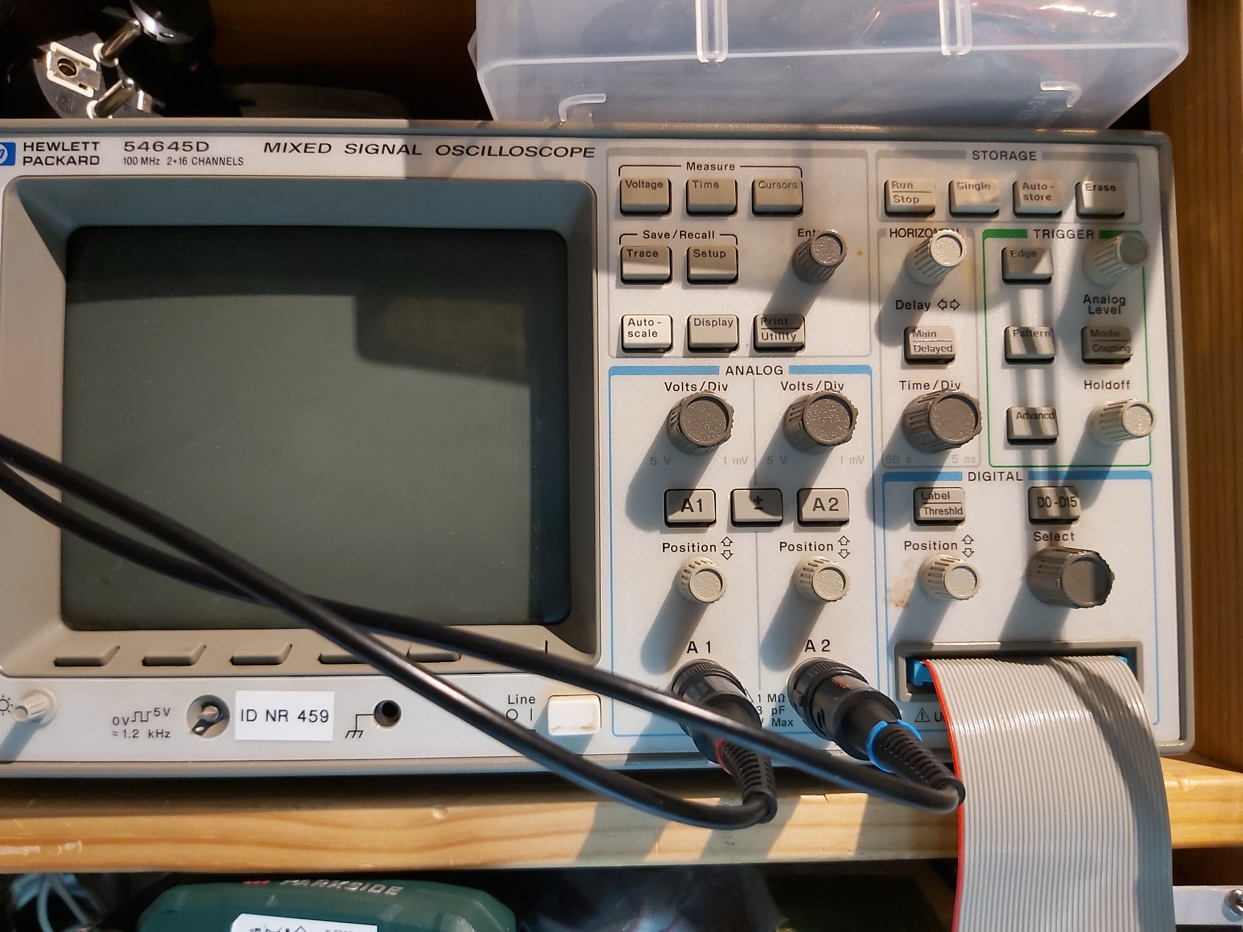
The 54645 was the first of the ones with MegaZoom so it has 4 megapoints memory both on analog AND digital combined. Megazoom is , apart from the large memory, basically a huge resampling asic that resamples the ‘slot’ you define in the memory and creates a 540 pixel wide image to screen.
Unfortunately I received the device without any cables. The oscilloscope probes are easy and cheap to buy. The bigger problem is the right cable for the logic analyzer channels. The device has 40 pin connector for 16 channels. The device says that you should only use recommended cables. O fear I’d take more effort and money to find the right pod for my scope than to buy a separate analyzer.
But I don’t give up. So I started to look for information how to get or build the right cables. I found the following pinout of 40 pin HP logic analyzer connector posted EEVblog Electronics Community Forum.
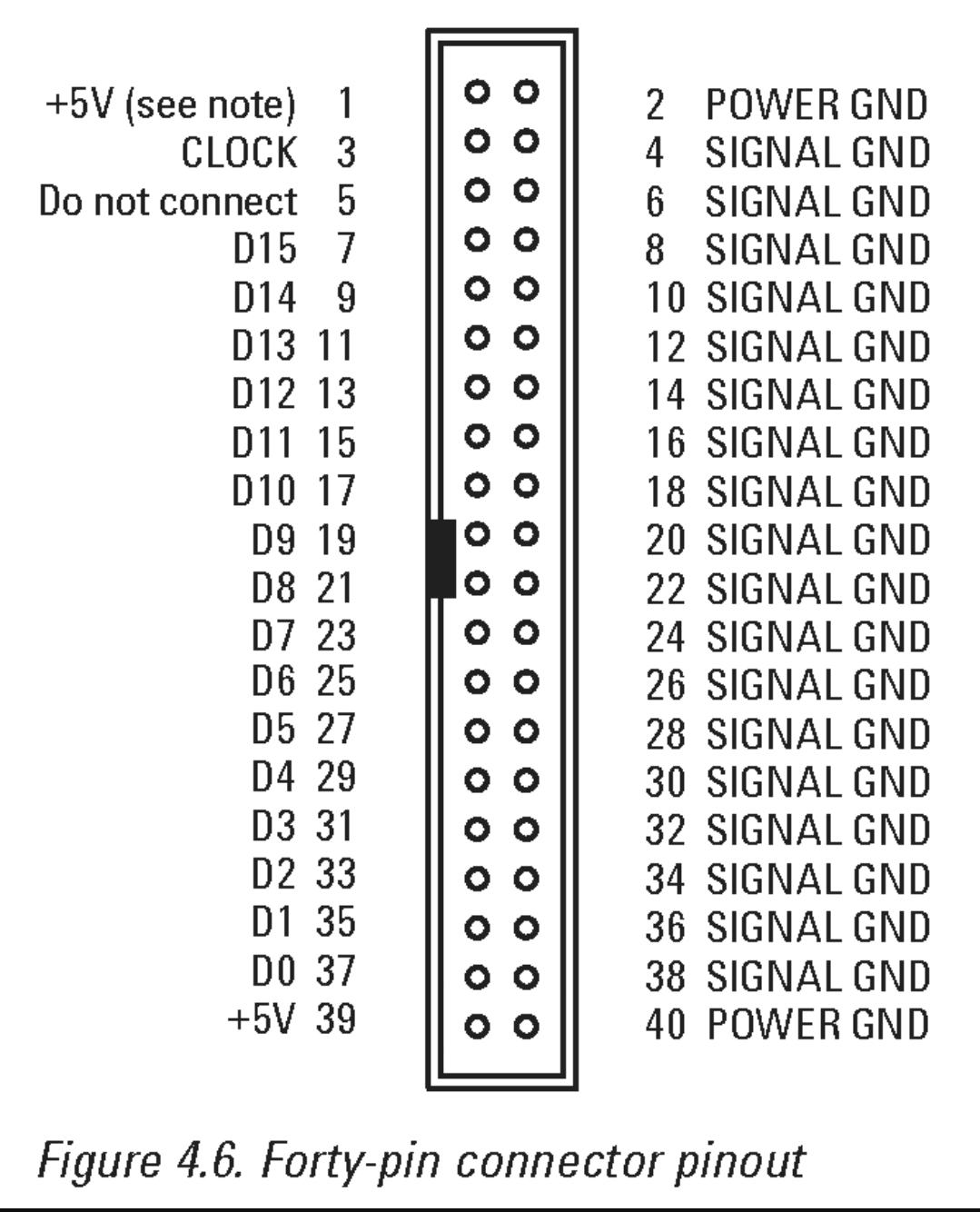
Even through the pinout was listed to be different device, HP has used pretty much identical pinouts on many different logic analyzer products and seemed to have cable sets that work with many different device models. That pinout above seems to match what I have in my device at least for data channel and ground pin usage.
The next thing is what else than just the cable there is. Discussion at EEVblog tells about the probes: They are not active, but do have components inside – simple RC networks. You can improvise with ribbon cable & resistors if necessary. Nothing in the box.
A few passives in each probe cable.
There is some material on probes for other HP model at https://www.eevblog.com/forum/projects/hp-e2310a-logicdart-probes-how-to-build-your-own-probes/
The description above clearly states that a resistive transmission line is used. Maybe I could live without one with somewhat reduced performance. At least I can plug 40 pin flat cable with connector to the connector on the front panel. And if I connect some logic signal to the right pins (from scope front panel test pin) I can get the logic analyzer to react to them. With more testing it seems that the voltage levels to what the scope reacts are not exactly the ones that I expect them to be (the scope turns on digital signal at considerably lower voltage than I expect it should).
There must be some tricks going on the cable or at the probe end. Could they be something like oscilloscope probes? The A wideband 1:21 DIY 1 kΩ oscilloscope probe article has the following description on scope probe suitability for logic analyzers:
If you have used conventional 1:10 oscilloscope probes to measure logic signals, you probably know that they have several limitations when edge rate falls. As logic signals get all the time faster, those ordinary probes become less and less useful. The main problem with 1:10 probes is their capacitive loading. At DC, the input impedance of 1:10 probe is 10 MΩ. 10 MΩ is a good thing when measuring high-impedance DC circuits like vacuum-tube amplifiers. For digital circuits, this figure is meaningless. It is the AC-loading which matters. Typical load capacitance value for 1:10 probe is 10-20 pF. At 100 MHz and 10 pF, that equals to 159 ohms. At 1 GHz, impedance is only one tenth of that figure, 15.9Ω!
So it seems that what is uses is different than normal oscilloscope probes. After some googling I found the following picture at https://www.eevblog.com/forum/testgear/diy-logic-analyzer-probe-and-pods-for-siglent-scopes/
That gives the idea what there could be. But it would be better if I could find some information from the right manufacturer. HP measuring equipment company is now called Keysight, and they have a relevant document at https://www.keysight.com/fi/en/assets/7018-06707/data-sheets/5968-4632.pdf
The document has some technical material on Keysight/HP 40 pin logic probes. There is this very good descriptive circuit diagram on the probe operation:
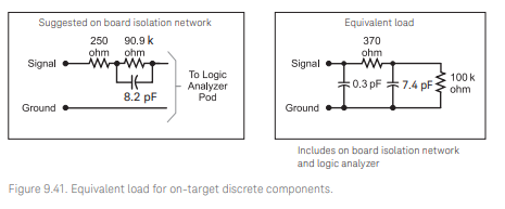
For testing purposes I built one test circuit that used 250 ohms resistor, 100 kohms resistor and 8 pF capacitor. It seemed to work somewhat acceptably on signal levels and also quite fast signals got though. Next plan is to built some more of those probe networks and do more testing. Here are my first channels wired with flat cable to the mixed signal scope.
In ended this experimenting with DIY cable when I got my hands to an original probe cable.
Links to more somewhat related info:
Hackaday has some interesting information on logic analyzers and logic probes.
EEVblog #44 Part 1 – Logic Analyzer Tutorial
https://www.youtube.com/watch?v=TWKY6W1C9yM
EEVblog #44 – Part 2 – Logic Analyzer Tutorial
https://www.youtube.com/watch?v=nAlNP-Z4QAQ
Digital Oscilloscope Set Up and Tutorial using HP 54645D Digital Storage Oscilloscope
https://www.youtube.com/watch?v=SrZtC6Yl3U0
HP54645D Mixed-Signal Oscilloscope
https://metalab.at/wiki/HP54645D_Mixed-Signal_Oscilloscope
29 Comments
Tomi Engdahl says:
HP 54645D Pushed to the MAX!
https://www.youtube.com/watch?v=SuOEWapx62c
In this video, I wanted to demonstrate how responsive and capable a vintage (1998) digital HP scope (HP 54645D) is. I’ve also demonstrated the FFT function from the Measurement module (HP 54659B), integration, derivative, XY mode, and lastly, pushed the scope with a 400 MHz signal with surprising results!
Highlights:
02:02 Horizontal MegaZoom
02:39 XY Mode (function gen and mic together)
04:13 HP 54659B Measurement Module (FFT and more)
09:40 Derivative measurement
10:38 Integral measurement
13:46 Spectrum of interrupted data
14:52 RF Measurement (starts at 10 MHz)
18:51 50 MHz, and limit of time division knob
19:36 80 MHz, and some interesting artifacts indicating how the ADC is timed
20:12 100 MHz
20:41 150 MHz
22:55 300 MHz!
24:42 400 MHz!
26:49 More fun with XY Mode
Tomi Engdahl says:
EEVblog #591 – Agilent 54622D Retro Mixed Signal Osciloscope Review & Teardown
https://youtu.be/aVNfFewFn_Y
Tomi Engdahl says:
How To fix the Buttons on an Oscilloscope (old Agilent Oscilloscope)
https://m.youtube.com/watch?v=sMPHIAu5zxw
Tomi Engdahl says:
Probing Solutions for Logic Analyzers
https://xdevs.com/doc/HP_Agilent_Keysight/agilentprobing.pdf
Tomi Engdahl says:
https://www.tek.com/en/datasheet/tektronix-logic-analyzer-probes
Key features
Low total capacitive loading minimizes intrusion on circuits
20 kΩ input resistance
7.5 Vp-pdynamic range supports a broad range of logic families
Variety of attachment mechanisms including the high-density D-Max®, Mictor, square pins, and flying leads.
Applications
Digital hardware validation and debug
Monitoring, measurement, and optimization of digital hardware performance
Embedded software integration, debug, and verification
https://www.tek.com/en/products/oscilloscopes/probes/logic-probe
Tomi Engdahl says:
Logic Analyzer Probes & Connectors Tutorial
Logic analyzer probes are the interface between the analyzer & circuit under test – their performance is critical for in electrical performance and usability.
https://www.electronics-notes.com/articles/test-methods/logic-analyzer/probes.php
Tomi Engdahl says:
Logic Analyzer Tutorial: Probe Setup
https://articles.saleae.com/logic-analyzers/logic-analyzer-tutorial-probe-setup
Types of Probes
Most logic analyzer probes can be organized into two categories: built-in and after the fact.
If you are designing a printed circuit board (PCB) for the purposes of prototyping, you may consider adding a special footprint for hooking up a logic analyzer connector.
If you are debugging a PCB that does not have a built-in logic analyzer connector, you can use “flying lead” probes. These probes are simply wires that you connect to the circuit in any configuration. Often, you will find flying lead probes with attachment heads that have a hook or grabber. These grabbers allow you to connect to a variety of wires, pins, and test points.
Tomi Engdahl says:
https://hackaday.com/2017/07/29/everything-you-need-to-know-about-logic-probes/
Tomi Engdahl says:
PCI Express™ Logic Analyzer Probing
Design Guide for Agilent Technologies
https://www.keysight.com.cn/cn/zh/assets/7018-08749/data-sheets-archived/5989-1172.pdf
Tomi Engdahl says:
https://www.eetimes.com/opinion-your-logic-analyzer-can-probe-those-forgotten-signals-2/
Tomi Engdahl says:
Digital Oscilloscope Set Up and Tutorial using HP 54645D Digital Storage Oscilloscope
https://www.youtube.com/watch?v=SrZtC6Yl3U0
Digital Oscilloscope Tutorial. Learn how to set up and use a digital oscilloscope using the HP Digital Storage Oscilloscope. Although this tutorial use one particular scope, the techniques should be helpful for most models of digital scopes.
Tomi Engdahl says:
HP 54645D Manuals
https://www.manualslib.com/products/Hp-54645d-2960596.html
Tomi Engdahl says:
https://www.eevblog.com/forum/testgear/should-i-sell-my-54645d-for-a-new-rigol/
Tomi Engdahl says:
https://www.eevblog.com/forum/testgear/16-channel-digital-probe-for-hp54645d-mso/
Tomi Engdahl says:
Some other model in this series had this feature
PLAYING TETRIS ON AN OSCILLOSCOPE
https://hackaday.com/2014/04/26/playing-tetris-on-an-oscilloscope/
Have engineers stopped putting Easter eggs into technology lately? It’s always been a fun way to connect with your more advanced customer base (i.e. hackers) — anyway, here’s a great Easter egg you can find on the Hewlett Packard 54600B Oscilloscop — Tetris!
Tomi Engdahl says:
https://www.cnx-software.com/2022/07/12/using-raspberry-pi-pico-as-a-logic-analyzer/
Tomi Engdahl says:
https://hackaday.com/2014/04/26/playing-tetris-on-an-oscilloscope/
https://imgur.com/a/343yN
Tomi Engdahl says:
Tom Verbeure Upcycles a Compact Sony CRT From an HP Logic Analyzer for a Retro Gaming Build
https://www.hackster.io/news/tom-verbeure-upcycles-a-compact-sony-crt-from-an-hp-logic-analyzer-for-a-retro-gaming-build-8e9f2f762ac3
Destined to provide a smooth picture for vintage games, this old Sony CRT is being freed from its home in an old HP logic analyzer.
Hardware engineer Tom Verbeure found himself with a long-outdated Hewlett-Packard logic analyzer, and after taking it apart found himself face-to-face with a compact Sony cathode-ray tube (CRT) — so set about turning it into a functional monitor for a compact retro gaming machine.
Tomi Engdahl says:
HP 16500A Logic Analyzer Teardown
https://tomverbeure.github.io/2022/06/17/HP16500a-teardown.html
Tomi Engdahl says:
https://metalab.at/wiki/HP54645D_Mixed-Signal_Oscilloscope
http://www.test-and-measurement.net/hp54645d.htm
Tomi Engdahl says:
https://www.keysight.com/us/en/product/54645D/100mhz-200msas-mixed-signal-oscilloscope.html
Tomi Engdahl says:
http://sine.ni.com/apps/utf8/niid_web_display.download_page?p_id_guid=E3B19B3E93B4659CE034080020E74861
Tomi Engdahl says:
Set up and tutorial
https://youtu.be/SrZtC6Yl3U0
Tomi Engdahl says:
https://www.manualslib.com/products/Hp-54645d-2960596.html
Tomi Engdahl says:
Pushing to max
https://youtu.be/SuOEWapx62c
Tomi Engdahl says:
https://www.eevblog.com/forum/testgear/hp54645d-print-screen-via-rs232/
Tomi Engdahl says:
https://hackaday.com/2022/11/10/computer-space-flies-again/
Part one is the intro, and [Sean] started with an HP logic analyzer, just probing the many TTL chips on the board looking for floating or otherwise suspicious outputs. Figure out the obviously faulty chips and replace each with a socket and new chip. Just about every diode in the machine needed replacing.
https://www.youtube.com/watch?v=EBnZJXByNCc
Tomi says:
https://sensepeek.com/webshop-1
Tomi Engdahl says:
https://www.eetimes.com/a-brief-recap-of-popular-logic-standards/