A valve amplifier or tube amplifier is a type of electronic amplifier that uses vacuum tubes to increase the amplitude or power of a signal. In audio applications, valves continue to be highly desired by most professional users, particularly in recording studios’ equipment and guitar amplifiers. Among stereo enthusiasts, there is a subgroup of audio buffs who advocate the use of tube amplifiers for home listening; they argue that tube amplifiers produce a “warmer” or more “natural” valve sound. Tube sound (or valve sound) is the characteristic sound associated with a vacuum tube-based audio amplifier.
Before the rise of the transistor in the 1950s, all amps used vacuum tubes. Still the audible significance of tube amplification on audio signals is a subject of continuing debate among audio enthusiasts. Audiophiles disagree on the relative merits of tube vs solid state amplification. Tube amplifiers have retained a loyal following amongst some audiophiles and musicians. Some musiciansprefer the distortion characteristics of tubes over transistors for electric guitar, bass, and other instrument amplifiers.
Today tubes are the incandescent light bulb of the audio world: an older, relatively inefficient technology that consumes a good deal of energy to output a modest amount of power. For power amplifiers solid state designs can be manufactured without output transformers and are therefore immune to speaker-dependent impedance mismatches and transforer effects. I have been long the person who has usef transistors for hifi applications and considered they to be better for hifi amplifiers.
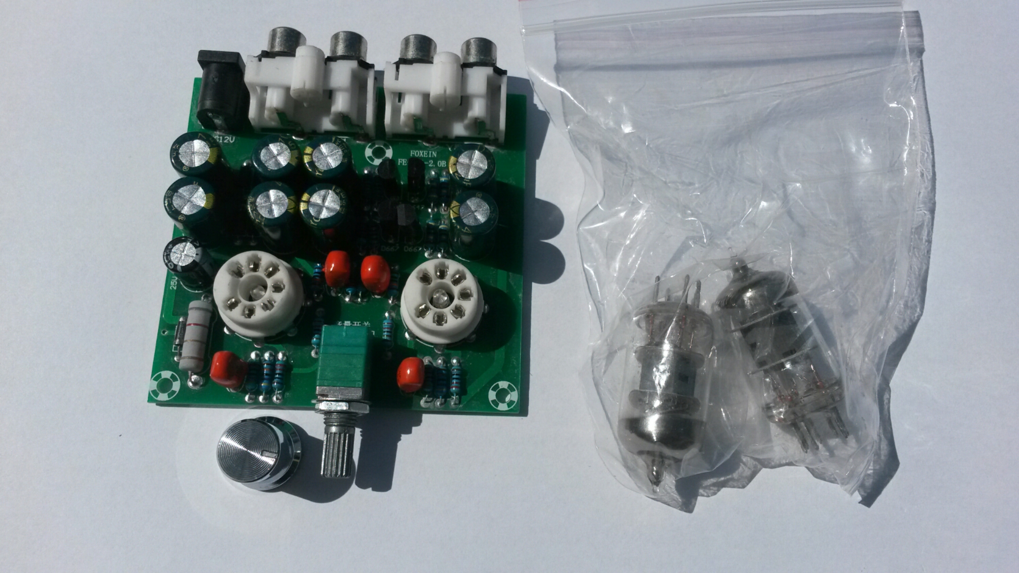
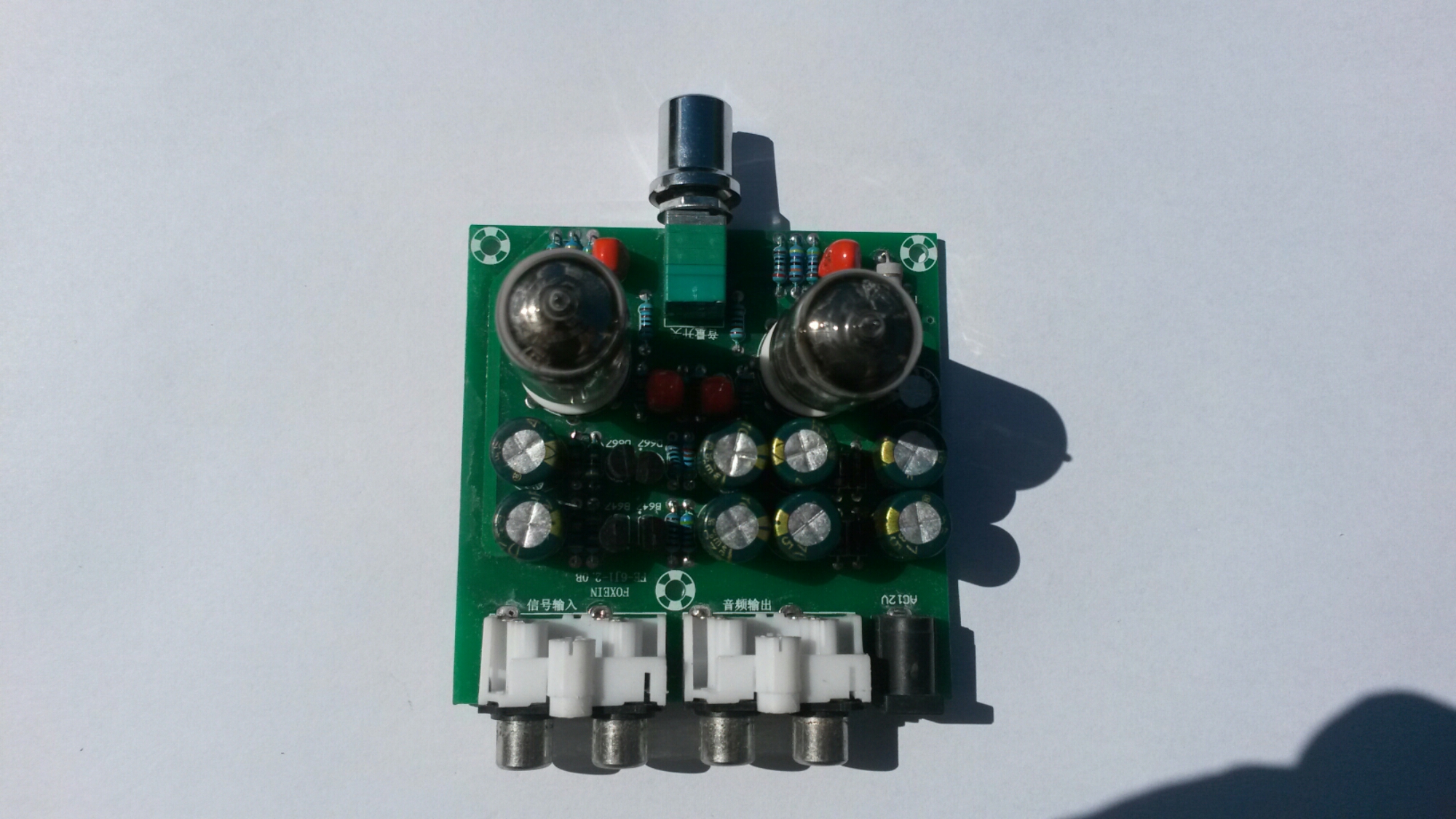
Tubes have their place in audio processing where you want to add to the sound the “warm tube distortion” sound (for example in guitar amplifiers). For preamplifer use tubes can work well. To get the idea of tube sound and how tube preamps works, I got this cheap kit for experimenting: AC12V/1A Stereo 2.0 Pre Amplifier Headphone Module Amplifier Buffer Board. It is a preamplifer that is suitable for conntrolling volume of line level audio signals (attenuate or amplify) and maybe add some magic tube sound to audio. Cheap way though of experiencing ‘tube sound’!
Type: FE-6J1-2.0B
Channel type: 2.0/ stereo
Power input: AC12V 1A / 5.5*2.5 plug
Knob function: Power switch / volume control
Size: 76 x 74 x 20mm
Pre-amp tube diameter: 18mm
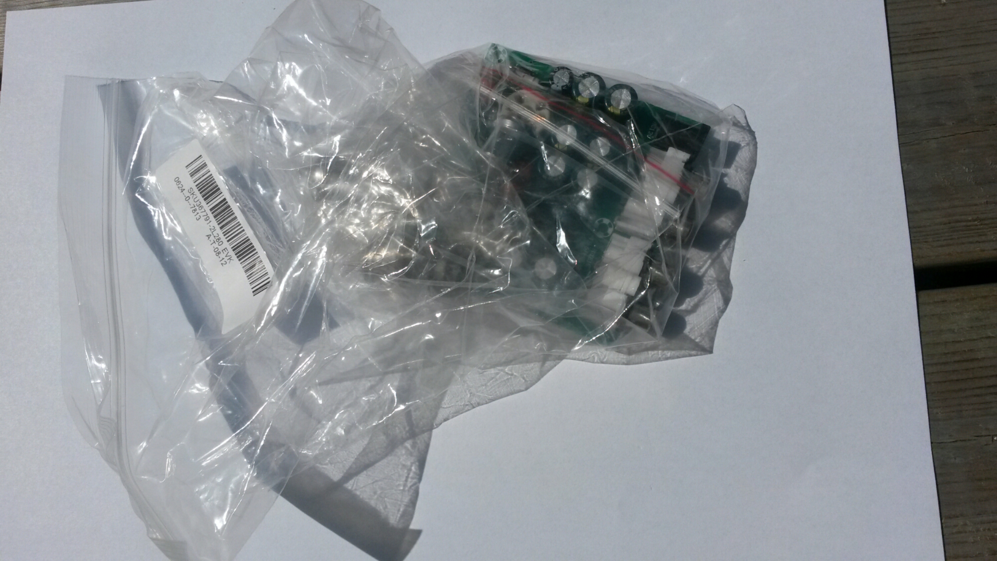
Everything was packed to a plastic bags.
There seem to be some small LEDs in the center of tube sockers. Those are blue LEDs that make the tubes to glow in blue color.
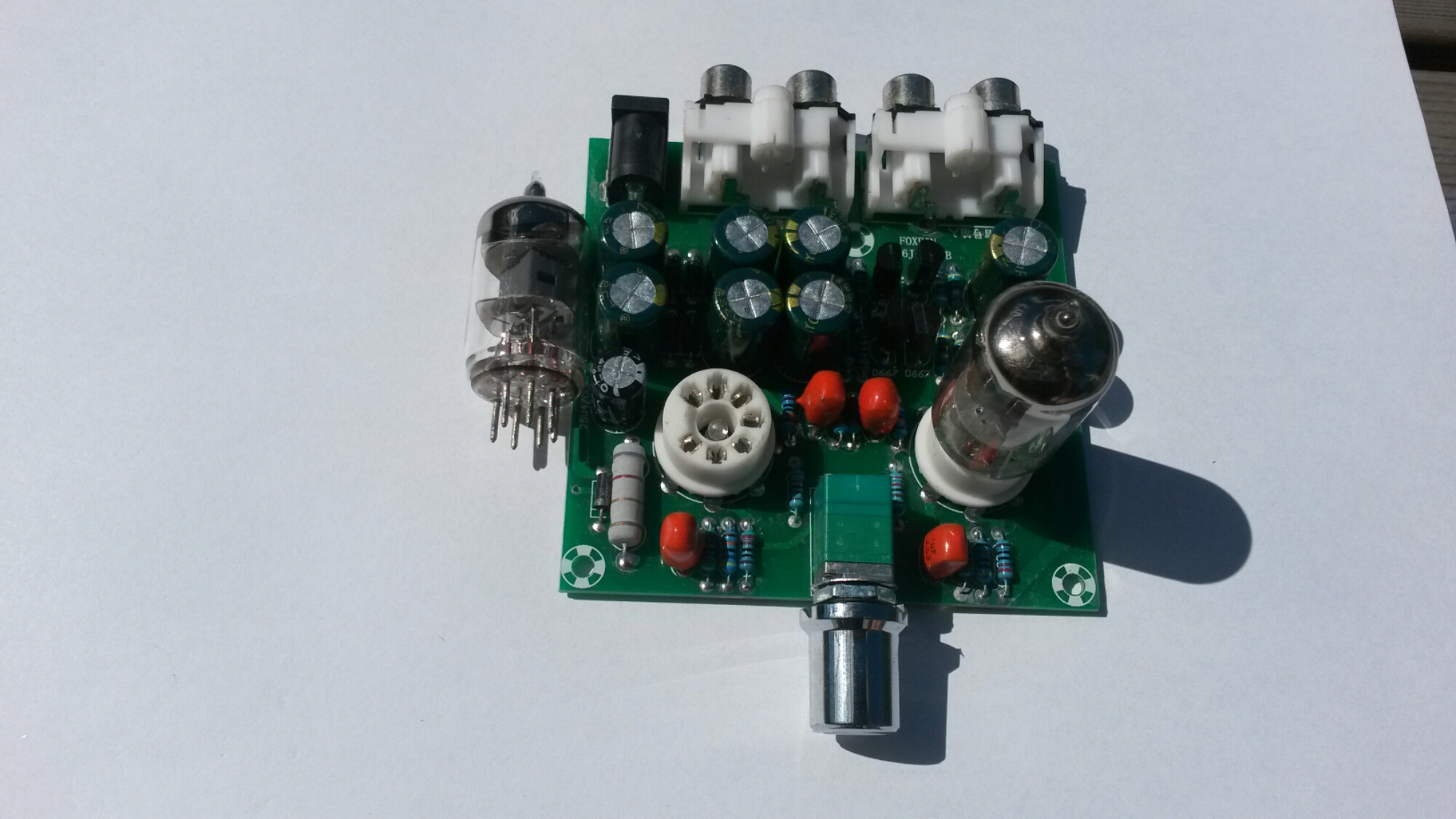
One tube installed.
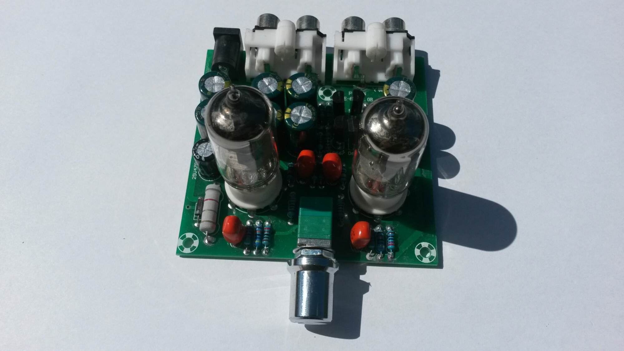
Two tubes installed.
The volume control in this board is combined volume control and power switch: The knob rotates counterclockwise to reduce the volume, when the volume to the hour, continues to rotate, until the “tick” sound, then power off, lights out.
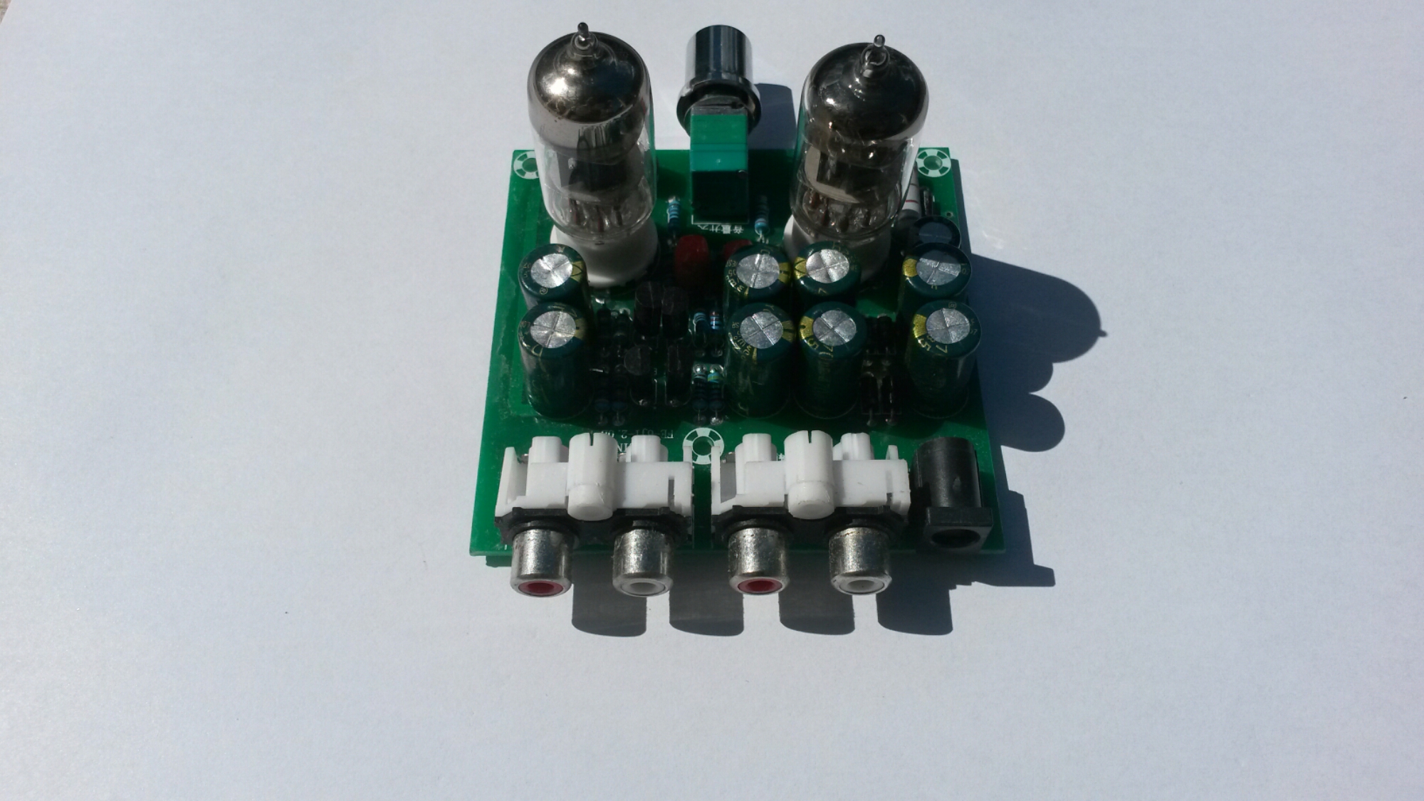
A look to the connectors…
On the left side: Audio signal input terminals that can be connected to mobile phones, computers, MP3, MP4, and other music player.
On the right side: The output terminal of the audio signal can be connected to an audio signal input terminal of a power amplifier and a power amplifier board. And next to them power input (12V AC 1A).
When I powered the amplifier, it did what it promised. It worked OK as a preamplifier.
Voltage amplification can be controlled from zero to around 6 times (around 15 dB).
The output worked on testing well to over 2Vpp input signal amplitudes at maximum amplitude without noticeable distortion on oscilloscope screen starting to appear.
The signal output impedance is around 3 kilo-ohms. That works well as line level signal preamplifier that drives power amplifier. This circuit is not headphone amplifier that drives headphones (if you thing if that from product name), it would would be pretty non-ideal headphone amplifier for low impedance headphones.
Does what it describes as preamplifier for audio signals. It sounds good, but I can’t find it to be adding any magic “tube sound” to the audio. The circuit adds some slight huming though (at more than about 1/3rd volume).
Note on powering: you need an (not DC) 12V plugpack or transformer. The kit says it needs 12V 1A power supply, so that what I used (I did not measure the actual power this circuit takes).
Ti get better idea how this circuit amplifier works, a circuit diagram would be nice. With some Googling I found that there are several pages that tell about this or very similar tube amplifiers:
https://www.circuitlab.com/circuit/9vnehk/fever-6j1-tube-pre-amp-circuit/
http://www.diyaudio.com/forums/tubes-valves/286349-6j1-tube-buffer-circuit-diagram.html
The best circuit diagram I could found was this at https://www.circuitlab.com/circuit/9vnehk/fever-6j1-tube-pre-amp-circuit/
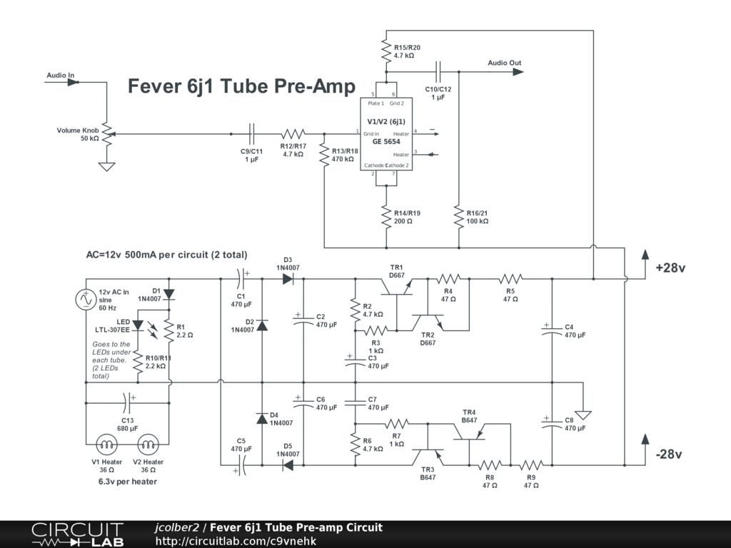
It seems to be mostly correct (shows only one channel), but has some small details that do not seem to be correct (for example connection of resistor on amplifier output should be connected to ground and not -28V). By the way the circuit diagram can be edited at https://www.circuitlab.com/editor/#?id=9vnehk
As you can see in the circuit diagram the power supply part converts the 12V AC input to +28V and -28V power rails that are used to power the tube. This means that the tube is run at 56V voltage (which is quite low voltage for an audio tube circuit, they typically operate at 100-300V voltage depending on tube type). This 56V voltage is good for safety – it does not hurt too much if you accidentally come in contact with this voltage when you test the board before putting it to case.
The power supply circuit consists of voltage multiplier + rectifier circuit followed with filter capacitors, some transistor circuitry (emitter follower with current limiting, somewhat resembles gyrator circuit) and more filter capacitors.
The tube heaters are directly powered from input 12V AC (two 6.3V heating coils in series can be powered from 12V AC).
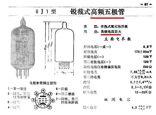
Information on the 6J1 tube used can be found at http://www.radiomuseum.org/tubes/tube_6j1.html and http://greatsound168.pixnet.net/blog/post/254453398-%E4%BA%8C%E5%8F%B06j1%E7%B7%A9%E8%A1%9D%E7%B4%9A%E7%9A%84%E5%88%86%E6%9E%90
Another preamp circuit using 6J1 tube at http://www.yunwt.net/1mydiy/qt14.htm
The basic design of this AC12V/1A Stereo 2.0 Pre Amplifier Headphone Module Amplifier Buffer Board seems to be sensible. If I had designd this I would maybe had designed few things slightly differently (for example power supply filtering and maybe tube heating) – that could have maybe reduced the slight mains humming on the output. Anyways as it isC12V/1A Stereo 2.0 Pre Amplifier Headphone Module Amplifier Buffer Board seems to be good quality cheap tube preamplifier.
317 Comments
Tomi Engdahl says:
Making tubes
https://www.facebook.com/share/v/1M9sf6ATYz/å
Tomi Engdahl says:
Subminiature Tubes: The Future of Audio!
https://www.effectrode.com/knowledge-base/subminiature-tubes/
Tomi Engdahl says:
Motorboating (electronics) – Wikipedia https://share.google/H6HkLvnCYlF2Ss3Y2
Tomi Engdahl says:
You could get more direct sound by skipping the tube preamp (as all of them are distortion making devices, some of which can be subjectively pleasing), and using a USB DAC with a volume control to feed your power amp directly.
Tomi Engdahl says:
écoute | A Tubeless Vacuum Tube https://share.google/NdYva3tLGEWMJM6Pz
Tomi Engdahl says:
Your mix listened to Chuck Norris, took notes, and remixed and mastered itself while deleting all other deliverables you were about to send the client.
Tomi Engdahl says:
An industry insider reveals that companies are already stockpiling to survive and warns that the market is closer to collapse than most realize.
Full story: https://www.headphonesty.com/2025/09/ongoing-tube-shortage-breaking-high-end-audio/
Tomi Engdahl says:
tubes in Class D? | diyAudio https://share.google/8Te3wtec3G8h4RaDr
Tomi Engdahl says:
tubeamp-pwm.gif (800×598) https://share.google/aBPfFBWy0y3DLhOwv
Tomi Engdahl says:
https://www.valvewizard.co.uk/
Tomi Engdahl says:
Tubes in car
https://www.facebook.com/share/v/14VEPKiVbdh/
Tomi Engdahl says:
The only good opamp is a tube opamp!
https://tubes.mit.edu/6S917/2025/labs/lab06
Tomi Engdahl says:
Nuvistor tubes were invented by RCA in the 1950s to solve the many shortcomings of conventional tubes. Unlike them, Nuvistor tubes offer very high reliability, low microphony, low noise, consistency from batch to batch, small size, relatively low power consumption and great technical performance. The tube is made entirely out of metal and ceramic meaning making nuvistors requires specialist equipment but also means that Nuvistors are among the highest performing small signal tubes on the market with the results of which can be seen in the Musical Fidelity Nu-Vista range accross the board.
https://loom.ly/T-2gpx4
#musicalfidelity #nuvistortubes #nuvistor #homeaudio
Tomi Engdahl says:
Tube Op Amp
An Op Amp from Tubes!
https://tubes.mit.edu/6S917/2025/labs/lab06?fbclid=Iwb21leAPsSzJjbGNrA-xLKGV4dG4DYWVtAjExAHNydGMGYXBwX2lkDDM1MDY4NTUzMTcyOAABHqFMBLT7zVjeEQuyC6Zu1scM_xEmZMAH1GTHfON1SiqaMW7jQkOtFWkxbaPg_aem_oyeZPd_17mfKV8QPBi7MCQ