Solderless breadboards are one of the most fundamental pieces when learning how to build circuits and prototyping simple circuits. A breadboard is a construction base for prototyping of electronics. Breadboard are the ideal way to check out small bits of circuitry that you’re not sure about.
Originally it was literally a bread board, a polished piece of wood used for slicing bread: when electronics were big and bulky, people would grab their mom’s breadboard, a few nails or thumbtacks, and start connecting wires onto the board.
In the 1970s the solderless breadboard (AKA plugboard, a terminal array board) became available and nowadays the term “breadboard” is commonly used to refer to these. Because the solderless breadboard does not require soldering, you don’t need soldering iron to build circuits and all parts including the board are reusable. This makes it easy to use for creating temporary prototypes and experimenting with circuit design.
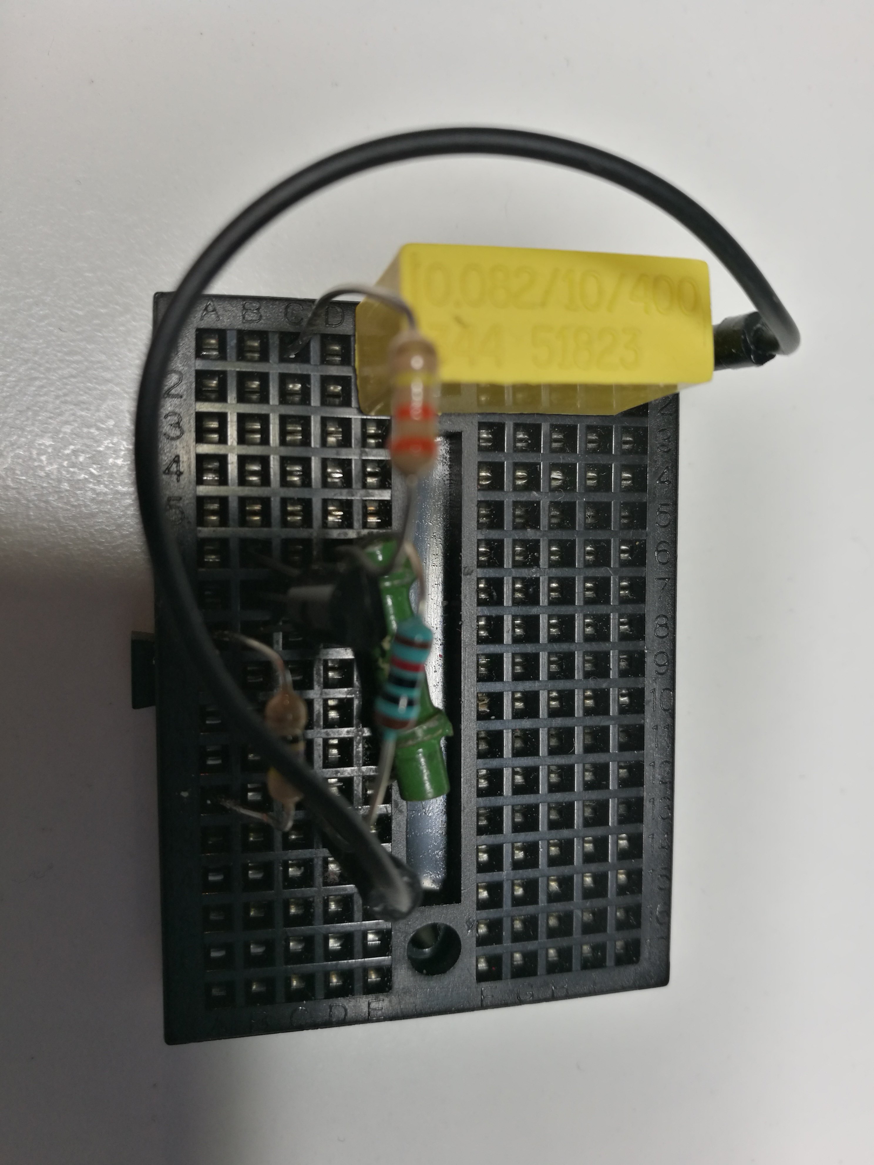
A modern solderless breadboard socket consists of a perforated block of plastic with numerous tin plated phosphor bronze or nickel silver alloy spring clips under the perforations. The clips are often called tie points or contact points. The spacing between the clips (lead pitch) is typically 0.1 in (2.54 mm). Integrated circuits (ICs) in dual in-line packages (DIPs) can be inserted to straddle the centerline of the block. Interconnecting wires and the leads of discrete components (such as capacitors, resistors, and inductors) can be inserted into the remaining free holes to complete the circuit.
Solderless breadboards are available from several different manufacturers. Jump wires (also called jumper wires) for solderless breadboarding can be obtained in ready-to-use jump wire sets or you can use any suitable solid conductor wire as jumper wire.
How to Use a Breadboard
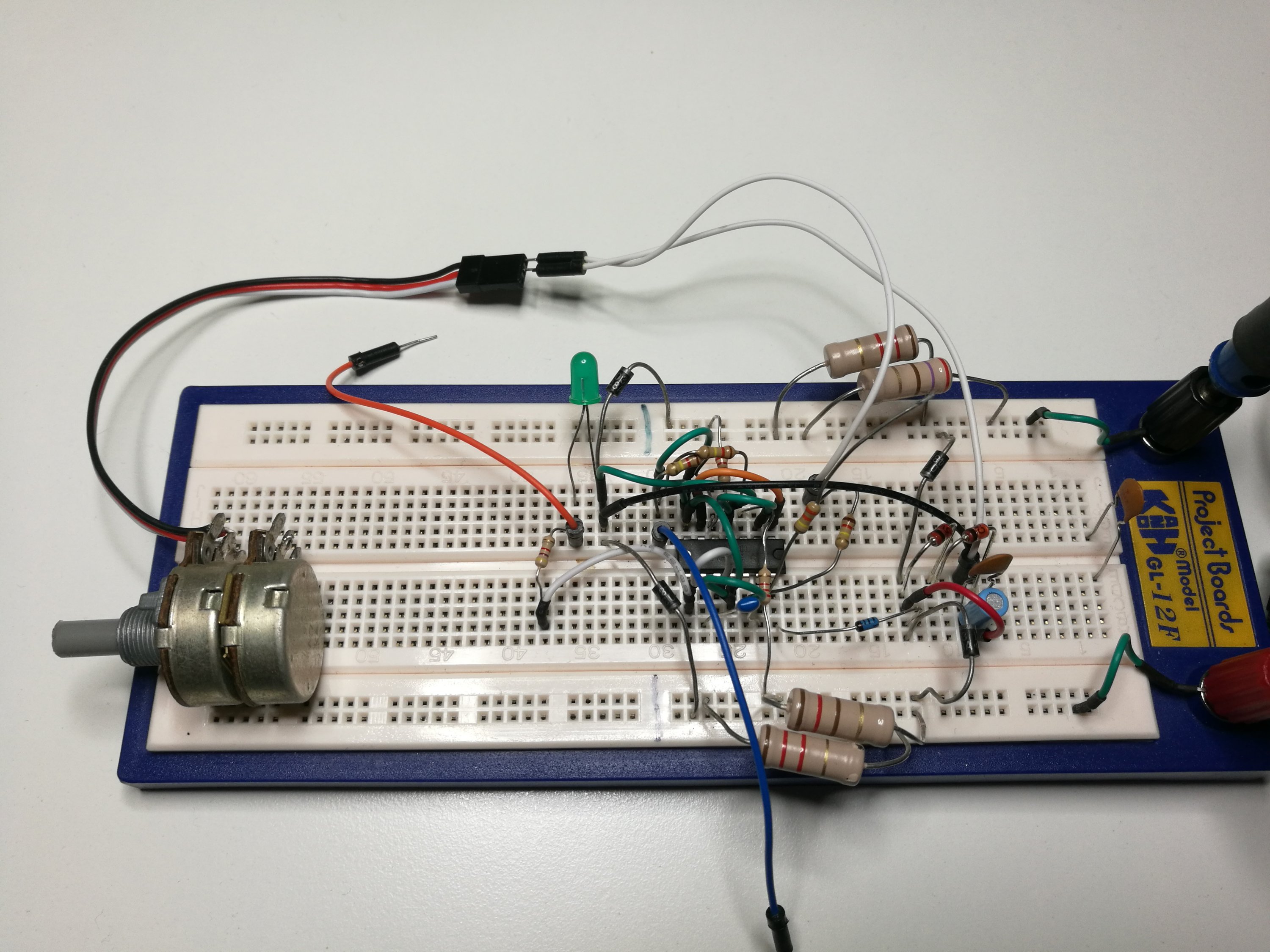
Prototyping is the process of testing out an idea by creating a preliminary model from which other forms are developed or copied, and it is one of the most common uses for breadboards. If you aren’t sure how a circuit will react under a given set of parameters, it’s best to build a prototype and test it out. The real beauty of breadboards is that they can house both the simplest circuit as well as very complex circuits.
Terminal strips metal rows have little clips that hide under the plastic holes. These clips allow you to stick a wire or the leg of a component into the exposed holes on a breadboard, which then hold it in place and make electrical contact. Once inserted that component will be electrically connected to anything else placed in that row. There is a ravine that isolates the two sides of a breadboard. This ravine serves a very important purpose allowing to connect ICs in DIP package to board – we can connect components to each side of the IC without interfering with the functionality of the leg on the opposite side.
You make the connections between metal rows with wired components and jumper wires. Typical board boards use 22AWG wire as jumpers. You can use solid 22 AWG wire pieces dirctly. Or you can buy ready made jumper wire set with connectors that plug nicely to board on their ends.
Links to some tutorials:
How to Use a Breadboard at Sparkfun
How to Use a Breadboard at Instructables
There are numerous options for powering breadboards. Some breadboards have binding posts that allow you to connect external power sources. The first step to using the binding posts is to connect them to the breadboard using some jumper wires. There are also special power supplies that plug to breadboard, like 3.3V / 5V Power Module for Breadboard I tested some years ago.
When IS it ok to use a breadboard? I’d say if the following cases are true it’s probably ok to use a breadboard.
- Rapid prototyping (not built to last)
- Few connections external to the breadboard
- Mostly thru-hole components
- Low voltage <= 12VDC
- Low frequency <= 10Mhz
Don’t try running lots of jumper wires from the breadboard to other devices or you will spend lots of time checking for broken connections.
Examples of interesting projects built to breadboard:
http://hackaday.com/2013/06/21/building-a-synth-on-a-breadboard/
http://hackaday.com/2013/09/26/breadboard-sequencer-does-a-lot-with-very-little-hardware/
http://hackaday.com/2013/09/28/breadboard-tetris-is-wire-artwork/
http://hackaday.com/2014/11/08/breadboarding-a-68000-computer-in-under-a-week/
http://hackaday.com/2016/03/07/breadboard-colecovision/
http://hackaday.com/2017/04/10/8-bit-breadboard-computer-is-up-to-8-hours/
Accessories and tips:
http://hackaday.com/2015/08/14/panel-mounted-breadboard-accessories/
http://hackaday.com/2011/09/27/diy-breadboard-modules-for-easy-prototyping/
http://embedded-lab.com/blog/diy-plug-in-modules-to-make-microcontroller-breadboarding-easier/
Electromechanical limitations
Breadboards cannot accommodate components with multiple rows of connectors if these connectors do not match the dual in-line layout—it is impossible to provide the correct electrical connectivity. Sometimes small PCB adapters called “breakout adapters” can be used to fit the component to the board.
http://hackaday.com/2012/11/13/make-dual-pin-header-footprints-into-breadboard-friendly-dip/
http://hackaday.com/2015/08/18/literal-breadboard-hack-forces-it-to-accept-dual-pin-headers/
Solderless breadboards usually cannot accommodate surface-mount technology devices (SMD) or components with grid spacing other than 0.1 in (2.54 mm). You typically need some adapter to connect SMD components to breadboard. Many SMD -> thru-hole adaptor boards are available online that will allow you to use SMD parts with a breadboard. SMD is easily handled with breakouts – SM discretes can be easily soldered to 0.1″ pin headers. The following web pages give tips for making and using such adapters:
http://hackaday.com/2014/07/25/using-surface-mount-devices-on-a-breadboard/
http://hackaday.com/2016/02/04/a-better-way-to-plug-a-cpld-into-a-breadboard/
http://hackaday.com/2016/04/20/make-your-own-esp8266-breadboard-adapter/
Electrical limitations
There are some limitations on breadboard performance for protyping that should be taken into account. Typically the spring clips are rated for 1 ampere at 5 volts and 0.333 amperes at 15 volts (5 watts). There are board with higher ratings, like for example 36V @ 2 Amps – if you plan to go to this powe range make sure that the board can handle it. General advice (unless you know for sure that it is OK) is never go above 1A since there is no restore button after you melted it. Breadboards are certainly not suited for mains voltage.
One thing that can also cause problems with these is the quality of the contacts. Some of those breadboards have quite weak mating points, so there are a lot of resistance variance. The relatively high and somewhat variable contact resistance can already be a problem for some circuits.
There is also a relatively large parasitic capacitance compared to a properly laid out PCB (approx 2pF between adjacent contact columns), high inductance of some connections and a relatively high and not very reproducible contact resistance. Because of those limitations solderless breadboards are limited to operation at relatively low frequencies, usually less than 10 MHz, depending on the nature of the circuit. Hackaday has article on Solderless Breadboard Parasitics. Heree are two videos on breadboard parasitic capacitance. First video shows capacitance measurements:
Second video tells about parasitics and shows what’s inside breadboard:
The inductance of the traces/wires also cannot be ignored especially for higher frequencies. This is another reason why breadboards are usually only suited for simple circuits well under 1Mhz, with higher frequencies may be possible if very carefully used). It’s one of those “it depends” things. For say TTL level digital stuff you can probably get away with running 10MHz on a breadboard if done carefully. On sensitive circuits even 100KHz is going to cause trouble due to the loop inductances, capacitance, and general dickiness. 2.5pF at 1MHz is about 63k ohms. If you have a circuit where stray 63k impedances are a problem then 1MHz is too high. A lot of digital circuits wouldn’t care about a stray 1k. Advice from eevblog discussion board: “In my experience, anything TTL that is readily available in DIL packages (say 74F/HCT/HC) is slow enough so stray capacitance of breadboard does not make much of a difference, you get effects of insufficient decoupling (which is not exactly trivial on breadboard) or even problems with correct probing much sooner than anything related to stray capacitance.”
Keep in mind that there is some capacitance between a contact and the ground plane formed by the metal plate that the board and binding posts are mounted on. Breadboard mounted on a metal plate can have ~2.5pF between contacts at 100kHz. If you are looking for a worst case scenario and add everything up: signal and ground on both sides (2*2pF) + power rail (1pF) + across center gap (1pF).
When to avoid using a breadboard
What are the cases where one should avoid using a breadboard? e.g. high frequency, noise prone circuits etc.
One thing you really shouldn’t try to use them for is any sort of switching regulator.
Areas where the common breadboard does poorly:
- High voltage
- High frequency (above 10MHz)
- Where the additional breadboard capacitance would present problems (oscillators, etc)
- Where glitches due to poor wire connections would result in poor operation
- Where most of the parts are not through hole 0.1″ (2.54mm) centers
- For anything but on-the-bench prototyping (ie, don’t take it out of the lab and expect it to work)
- Sensitive analog electronics, such as sensor usage
Particularly I’m almost not using more breadboard. It’s rare. – Daniel Grillo
Be warned that with any complicated circuit on breadboard you will end up spending lotsof the time troubleshooting the breadboard. The probability of dodgy connections means that larger designs are more prone to problems and should probably be avoided.
If you are building something that has may components, consider if it would make sense to hardwire the circuitry. It does not take too much longer with right tools. You can something like Veroboard or make PCB at home if I need a prototype quickly.
7 Comments
Tomi Engdahl says:
8-bit breadboard TTL CPU
https://hackaday.io/project/26350-8-bit-breadboard-ttl-cpu
Tomi Engdahl says:
Boobytrap breadboard from China.
https://www.youtube.com/watch?v=E5JlaC9m8Go
I was using this piece of breadboard for choosing component values for a simple circuit. I’d bought it some time back from a typical Chinese ebay seller. While testing the circuit I just couldn’t get it to work. I double and triple checked all the connections and swapped components, but it still didn’t work. It was only when I actually started metering it out that I discovered that the breadboard does not have continuous bus strips at the top and bottom. Instead they are divided into three sections each with no markings on the front to indicate that.
Tomi Engdahl says:
Collin’s Lab: The REAL Breadboard
https://www.youtube.com/watch?v=HrG98HJ3Z6w
Collin’s Lab: Breadboards & Perfboards
https://www.youtube.com/watch?v=w0c3t0fJhXU
Tomi Engdahl says:
Making Your Breadboard Projects A Little More Permanent
https://hackaday.com/2019/01/06/making-your-breadboard-projects-a-little-more-permanent/
Many a budding electronics maker got their start not with a soldering iron, but with the humble breadboard. With its push connections, the breadboard enables electronics experimentation without requiring the specialised skill of soldering or any dangerous hot tools. What it lacks is a certain robustness that can make all but the simplest projects rather difficult to execute. [Runtime Micro] have shared a few tips on making things just a little more robust, however.
The fundamental principle behind this process is replacing point-to-point jumper wires with custom cables, made using 0.1″ pitch headers and wire-wrapping techniques.
Permanent Solderless Breadboard Projects
https://runtimemicro.com/Construction/Permanent-Solderless-Breadboard-Projects
Permanent Solderless Breadboard?
The Permanent Solderless method combines Breadboards, thru-hole Headers and Wire-Wrap to make resilient electronic projects. Because flimsy push-wires (also called jumpers) are eliminated, circuits are more tolerant of impact and vibration. And that translates into long lasting builds with decent reliability.
Are Thru-Hole Headers Suitable for Wire Wrap?
Yes! Thru-hole Headers have tenth-center spacing and square .025 inch posts. They can be inserted (with care) into AWG #21-22 compliant Breadboards.
Tomi Engdahl says:
Custom Cables for Solderless Breadboards
https://runtimemicro.com/construction/custom-cables-solderless-projects
Building with Solderless Breadboards typically means using push-wires to make MCU, Module and Breadboard connections. Your Project eventually grows a wiring rats-nest. You might think there’s no way around this.
But what if you could use Custom Cables to make those Header-like connections? That rats-nest would shrink or perhaps even disappear! Project reliability and appearance would improve immediately.
Well, you can make those connections using Custom Cables of exact length and wire count! Its accomplished using thru-hole Headers, a Wire-Wrap tool and some 2-side sticky tape. The technique is low cost and easy to learn! Check this out…
Tomi Engdahl says:
Everything is a trade-off. On one side, you have holes available per row.
On the other, you have size and expense. Plus parasitic capacitance, of about 2-3pF row to row, and 20pf rail to rail.
Tomi Engdahl says:
Are you tired of using wires? Tired of putting chips in the board? Maybe you just want to pretend you’re using a breadboard when you’re not? There’s a solution for that!
https://hackaday.com/2023/08/25/hackaday-prize-2023-jumperless-the-jumperless-jumperboard/