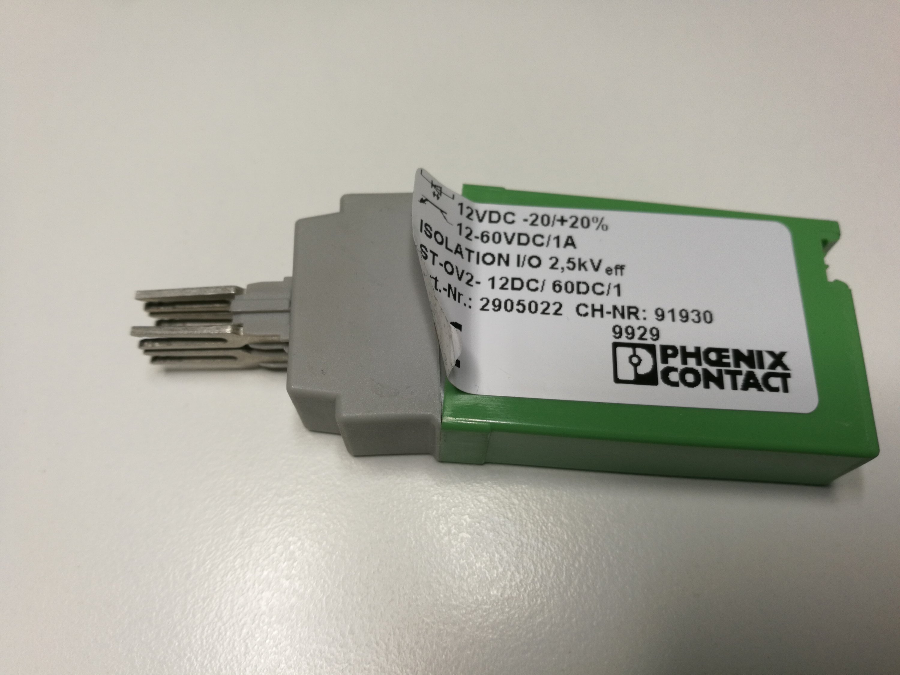
Here is a tear-down of ST-OV2- 12DC/ 60DC/1 – 2905022 solid state relay from Phoenix Contact. This product is old, obsolete and manufacturing has been discontinued.
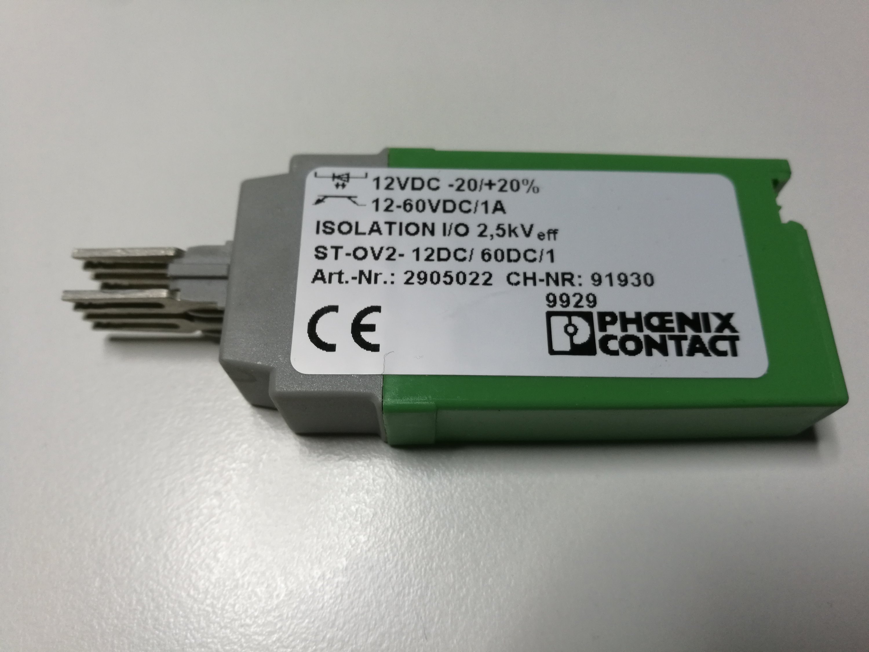
Solid-state relay ST-OV2- 12DC/ 60DC/1 – 2905022 is a plug-in power solid-state relay (plug to certain Phoenix Contact wiring terminals), with LED and protective circuit in input and output circuits. Here is a simplified circuit diagram (from manufacturer data) of this solid state relay model:

This relay model has nominal input voltage of 12V DC. The relay output is designed to drive load at 12 – 60 V DC voltage range and maximum 1A current. More detailed data:
Input data
Nominal input voltage UN 12 V DC
Input voltage range in reference to UN 0.8 … 1.2
Input voltage range 9.6 V DC … 14.4 V DC
Switching threshold “0″ signal in reference to UN ≤ 0.4
Switching threshold “1″ signal in reference to UN ≥ 0.8
Typical input current at UN 7 mA
Typical response time 20 µs
Typical turn-off time 200 µs
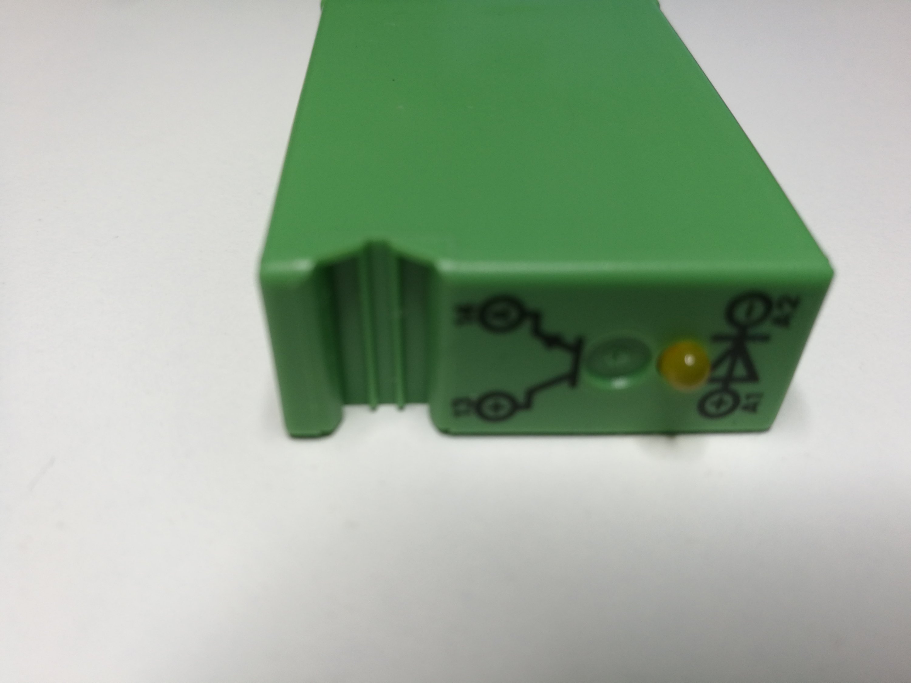
Status display Yellow LED
Type of protection Reverse polarity protection
Surge protection
Protective circuit/component Polarity protection diode
Transmission frequency 500 Hz
Output data
Output voltage range 12 V DC … 60 V DC
Limiting continuous current 1 A (see derating curve)
Surge current 5 A (t = 1 s)
Peak offstate voltage 60 V DC (Collector-emitter reverse voltage)
Voltage drop at max. limiting continuous current 1.2 V
Output circuit 2-wire, floating
Type of protection Reverse polarity protection
Surge protection
Protective circuit/component Polarity protection diode
General
Test voltage input/output 2.5 kV AC
Mounting position any
Standards/regulations DIN VDE 0110b, Gr. C for 250 V DC
DIN VDE 0160 (in relevant parts)
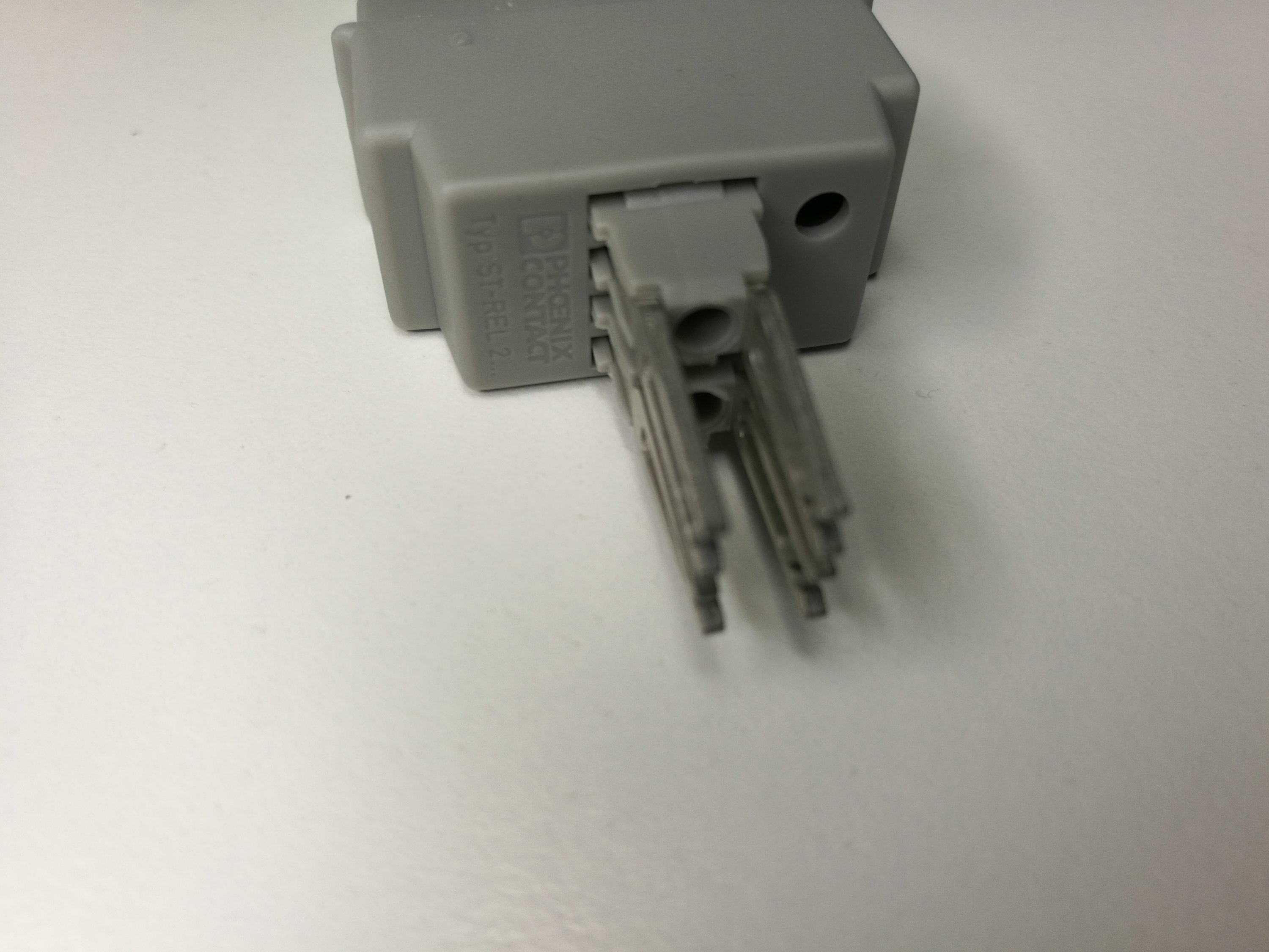
Let’s take a closer look at the product:

Let’s open the case:
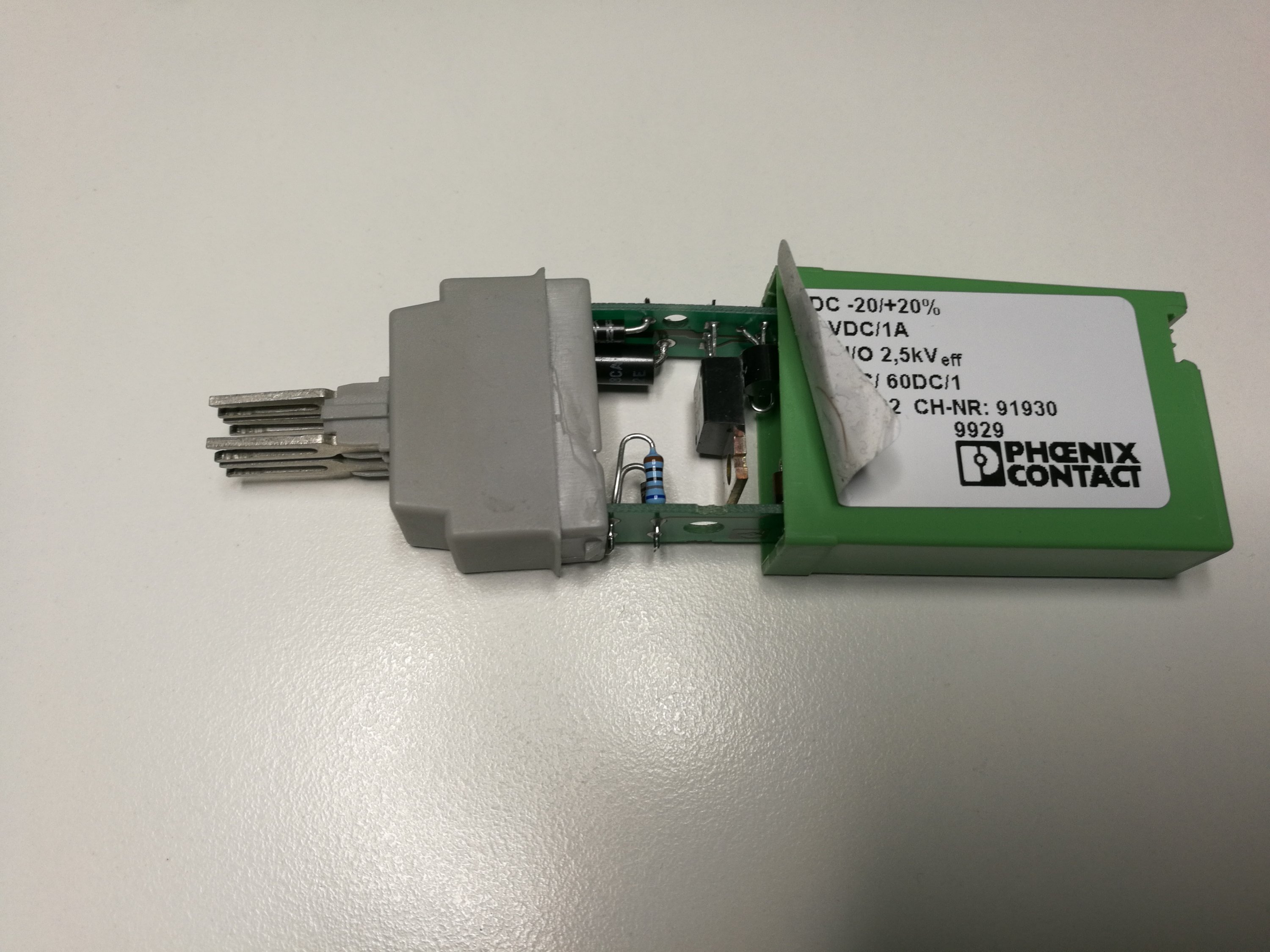
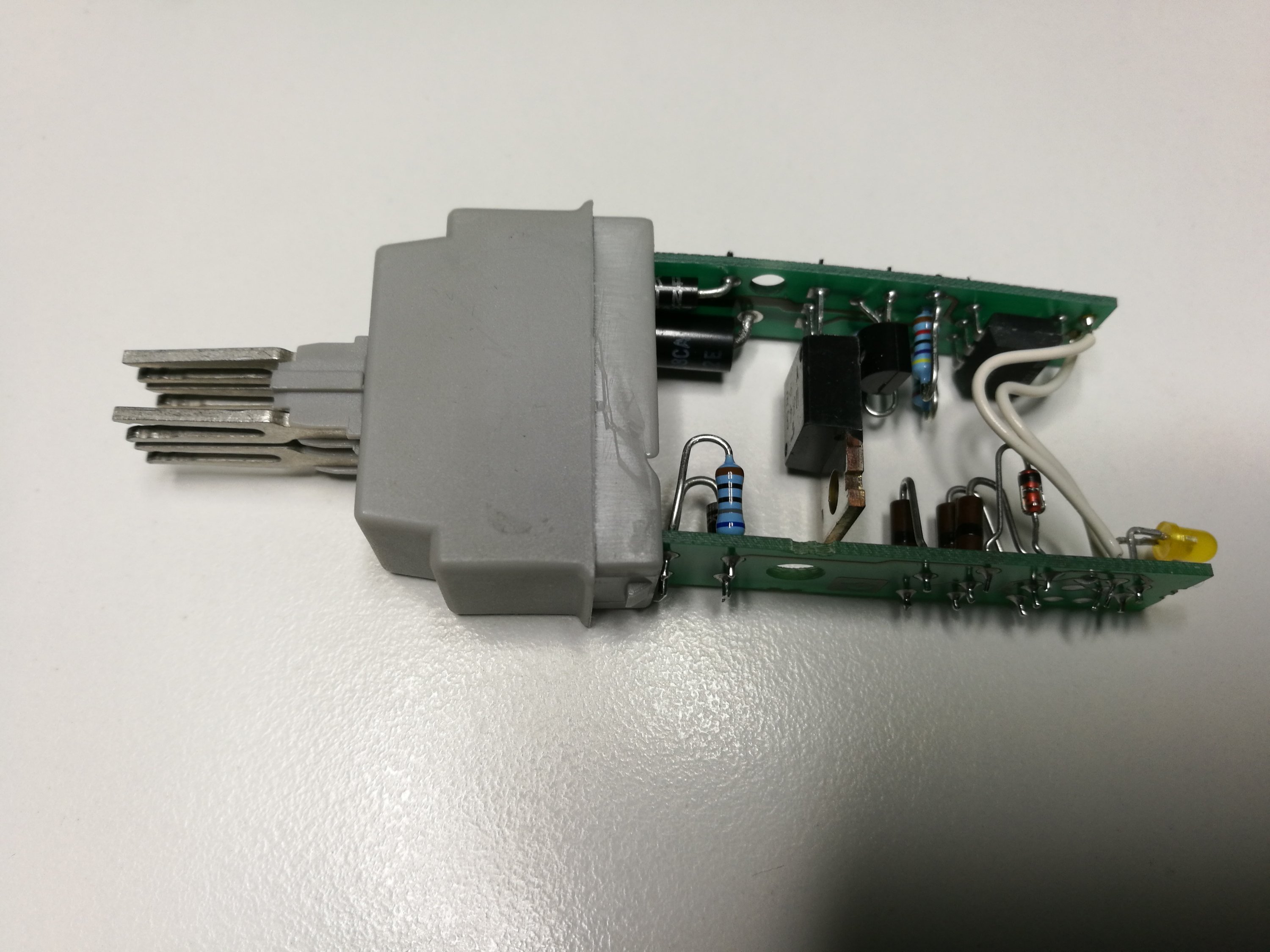
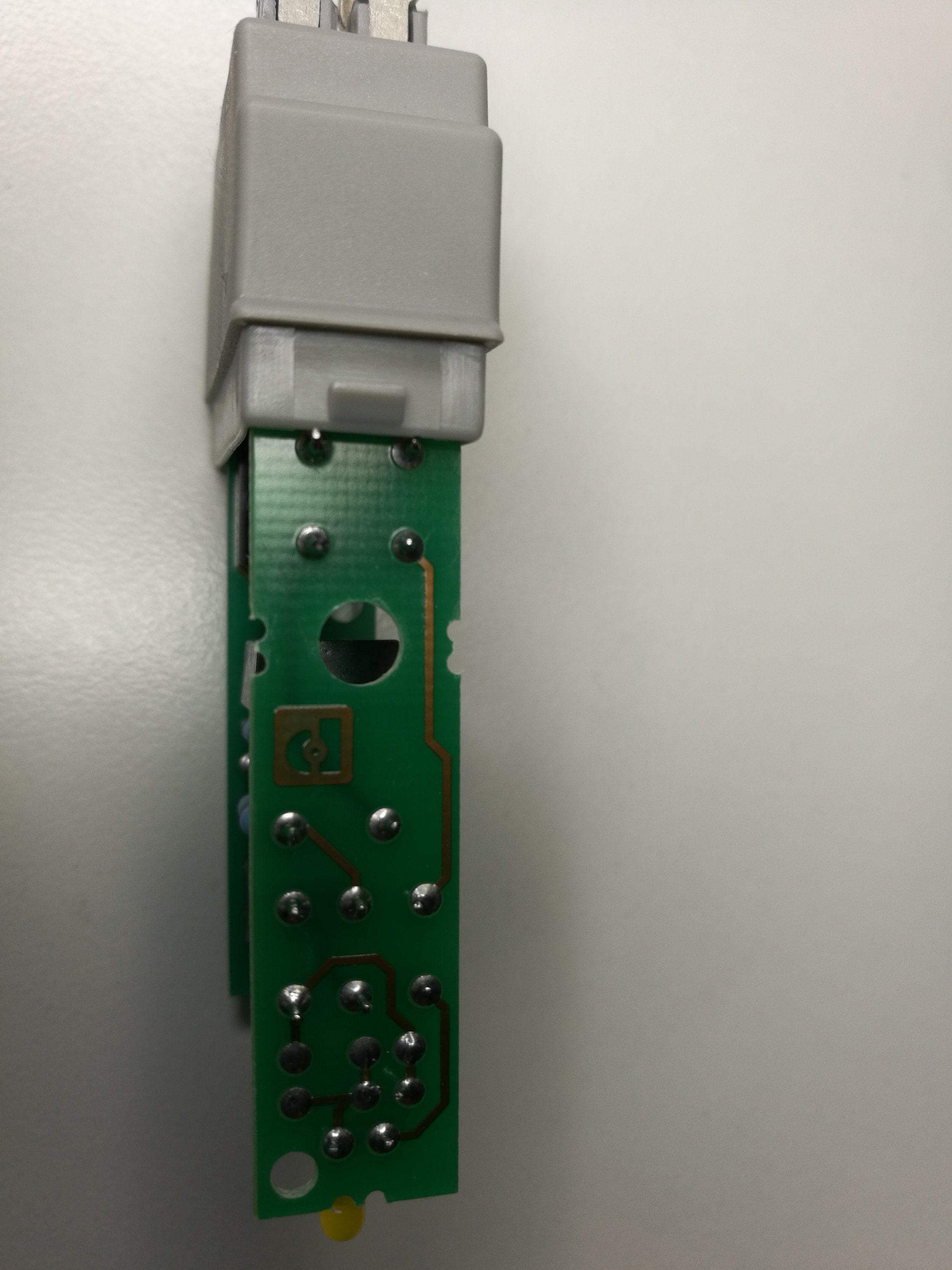
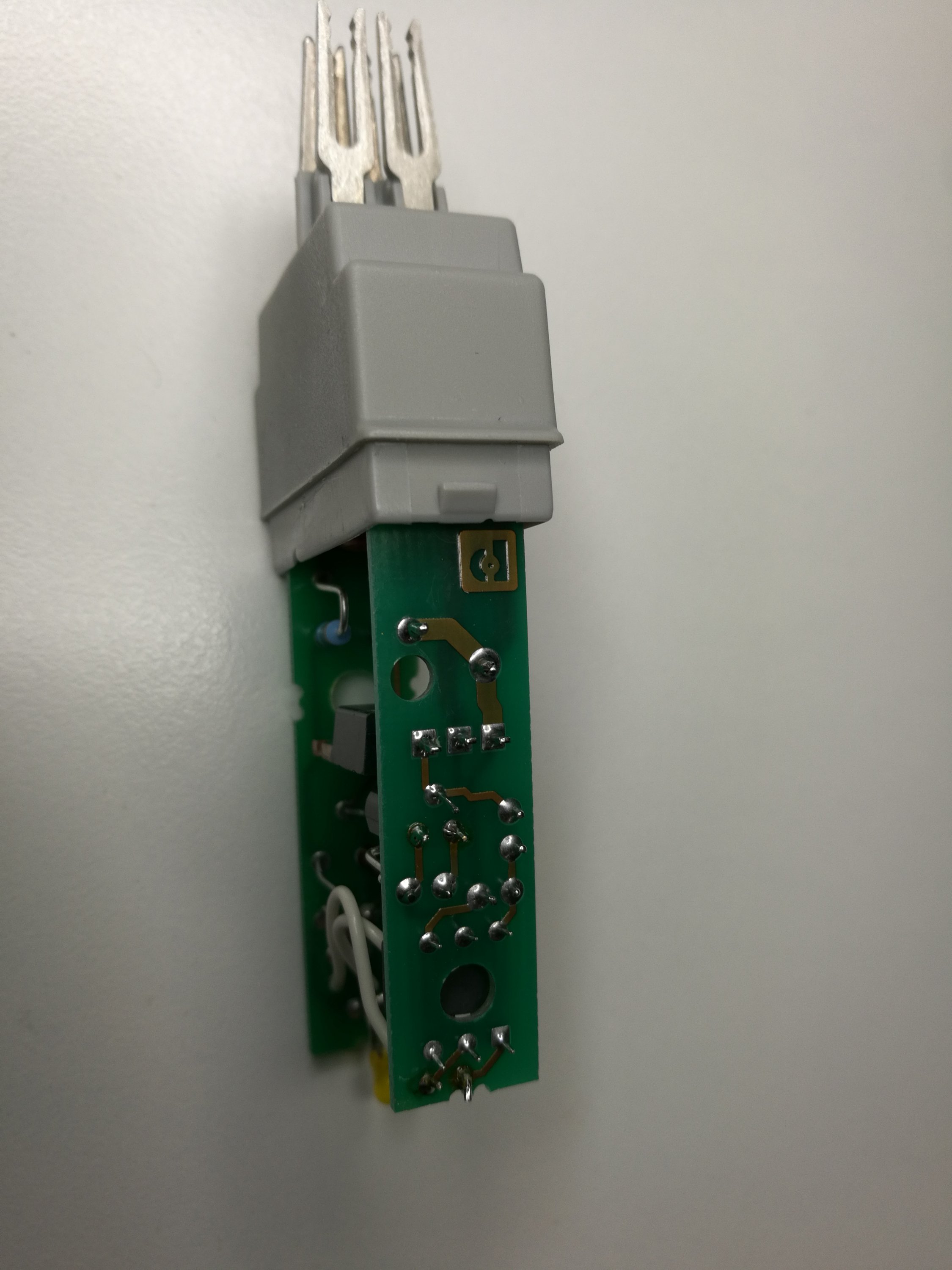
A look at electronics inside. This looks quite complicated construction that has many components and two circuit boards.
The product data also gives this kind of drawing that describes the circuit protection built into the relay:

Here is my hand drawing of the circuit inside SSR:
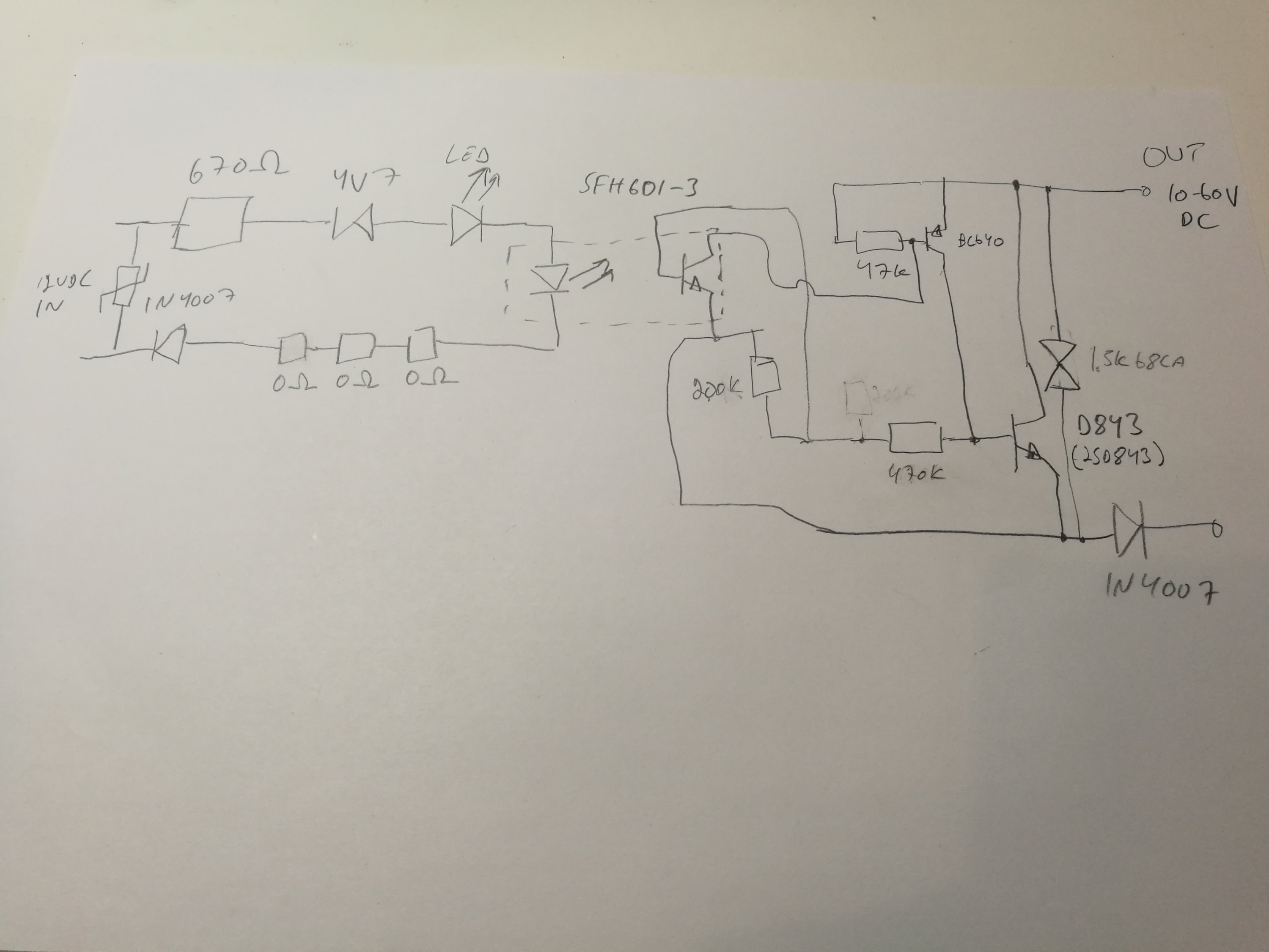
The signal input circuit is pretty basic consisting of polarity protection diode, current limiting resistor, zener diode and optocoupler LED. There is also a VDR between input pins for over voltage / surge protection. Those three zero ohms resistors make me wonder why they have used so many resistors. The reason for this could be that because there are variations of this relay also for other voltages (for example 24V DC input and 110V DC input), and on those higher voltage versions there could be need to use several resistors in series (to meet voltage and/or power handling ratings needed).
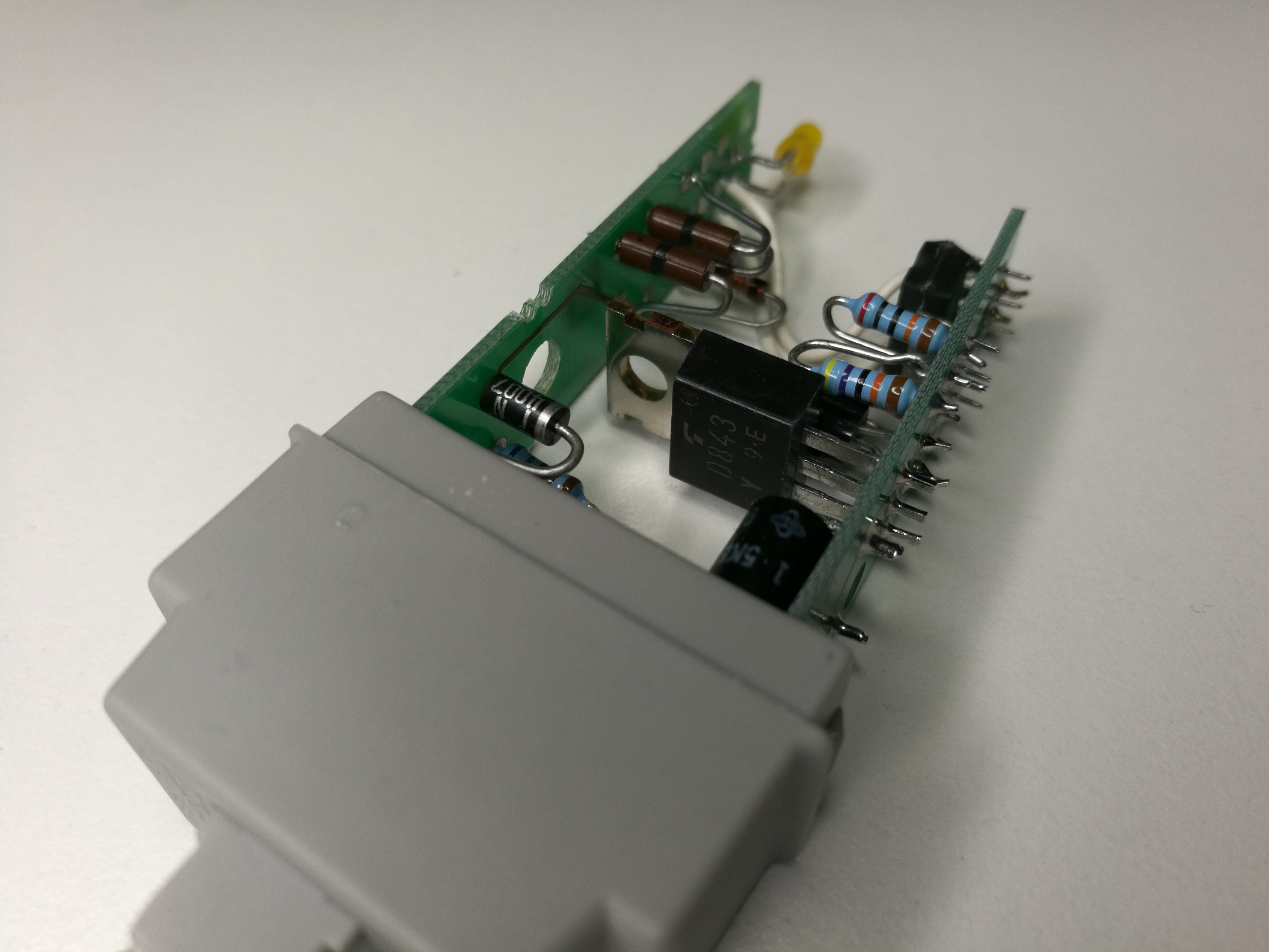
The output side is implemented with NPN power transistor that is driven with optoisolator output amplified with one PNP transistor. The all output transistors and optoisolator output have high enough rating to handle the full output voltage. On the output there is a surge protection component between output pins (striking voltage 65-71V). Theoretically the power transistor itself could handle much more current than 1A, but I think the output is limited to 1A because of thermal constraints (just transistor inside small case). Other limiting factor is that the IN4007 diode on the output is rated only for 1A current.
Component data of most important components:
2SD843 NPN power transistor (Vce 80V, Ic 5A , 40W, 10 MHz, hFE 70)
BC640 PNP transistor
SFH601-3 optoisolator
1.5K-68CA Transient Voltage Suppression Diode
2 Comments
Tomi Engdahl says:
The output circuit has somewhat interesting circuitry that goes to base of optoisolator output transistor.
My quess on the output circuit is there to introduce some hysteresis to the circuit operation (similar to electro-mechanical relays), meaning that when the control that turns on the output is reaches, the drive needs to be considerably lowered to to turn the output off again.
Tomi Engdahl says:
https://www.phoenixcontact.com/en-pc/products/solid-state-relays-st-ov2-12dc-60dc-1-2905022