I saw a request for circuit diagram in Facebook electronics group: Hello feds. Required surge protector circuit. Working on 220v. 50hz 10amps load.
I first offered this reverse engineering of one commercial mains surge protector “Ahlstrom 23 368″.
The manufacturee component codes of the exact components used.
S20K250 is a varistor for 250V AC / 320V DC (390V varistor operating voltage) 140J 8kA
UZ470B32 is a gas discharge tube surge arrestor with voltage rating of 470V
Unfortunately it seemed that the UZ470B32 TUBE was no longer available.
Then I mentioned that some commercial surge protectors and built in protection inside some power supplies have been built with only VDR between live and neutral (and some cases between neutral and ground, and sometimes even live and ground).
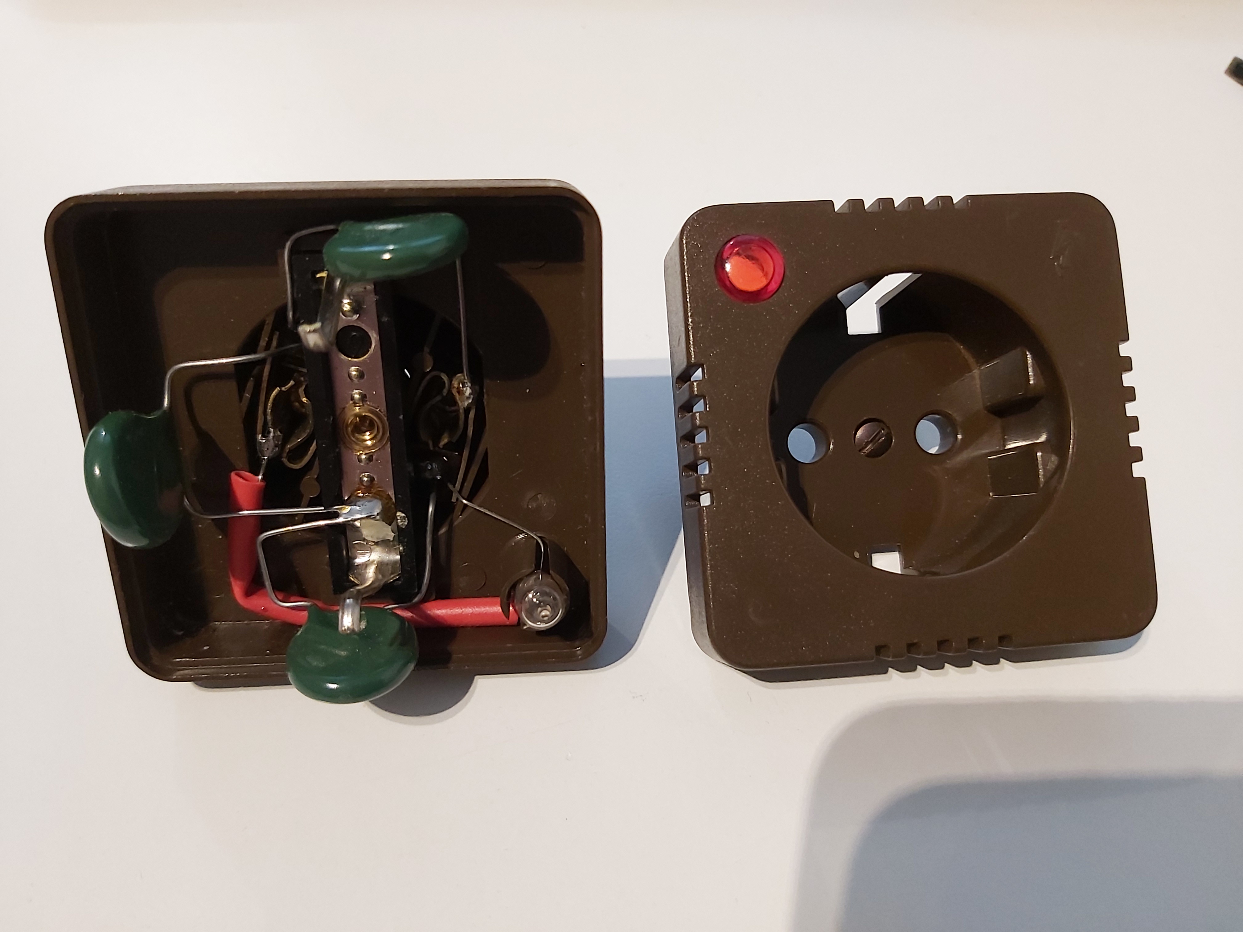
I decided to make a tear-down and reverse-engineering of another commercially sold surge protector (no brand name on case). It uses three 14D471 varistors and indicator lamp (glimm lamp with 120 kohms current limiting resistor). The 14D471 varistors are 14 mm diameter 470V DC rated (300V AC). One is between live and neutral. The other two are from live to ground and neutral to ground.
18 Comments
Tomi Engdahl says:
https://www.epanorama.net/documents/surge/surgesuppres.html
Tomi Engdahl says:
https://www.edn.com/a-circuit-simplification-for-ac-power-supply-surge-protection-devices/
Tomi Engdahl says:
Lightning/Surge Protector Circuit Using Gas Discharge Tube (GDT)
https://www.circuitstoday.com/lightningsurge-protector-circuit-using-gas-discharge-tube-gdt
Tomi Engdahl says:
Y08UZ-470B New plug-in ceramic gas discharge tube UZ470B 470V lightning pipe U-9B 2R470.
https://www.yoycart.com/Product/521928929749/
Tomi Engdahl says:
Never Use a Surge Protector with a Step-Down Transformer
https://www.gson.org/stepdown/
Tomi Engdahl says:
SurgeX Surge Protection Demo
https://www.youtube.com/watch?v=dlByve0r7GE
See how SurgeX Advanced Series Mode surge protection technology safeguards electronic equipment.
Tomi Engdahl says:
How different surge protectors respond to a surge
https://m.youtube.com/watch?v=fqR4N9LH0Qs&feature=youtu.be
This short white-board demonstration shows how various surge protection technologies acts when a surge passes through a power line.
Zero Surge is a USA manufacturer of series mode failure-free surge protection products for computers, TVs, gaming consoles, audio equipment, copiers, security systems, CPAP and medical equipment, laboratories, Point of Sale systems, digital menu boards, teleconferencing equipment, CNC machinery, and countless other sensitive electronics. The product line consists of plug-in point of use products, 20 Amp branch circuit panel mount models, and OEM open chassis modules for inclusion in a manufacturer’s product design.
Spectrum WVR – Wide Voltage Range Technology-
Typical surge suppressors use fixed clamping level components such as Metal Oxide Varistors (MOVs) that do not even begin to function until their clamping level is exceeded, allowing damaging energy through until that, often too high, level is reached. Using a patented dynamic clamp surge inversion system, Zero Surge’s Spectrum WVR effectively senses and suppresses surges on your 120VAC power line even when the power is low at 85 Volts or high at 175 Volts and anywhere in between. This is especially beneficial when the voltage is variable and unpredictable, during brownout and blackout conditions, and when standby generators are in use.
Tomi Engdahl says:
What you need to know about SPDs
https://www.youtube.com/watch?v=S85iSQ3_kQo
After one of our last videos, we had a lot of people wanting to know more about SPDs and how they actually work. With a lot of people still opting to not use them on their installations.
So we dig into the three main questions:
1) What are Type 2 SPDs
2) How do they work
3) Do they need Overcurrent Protection?
Tomi Engdahl says:
To protect against lightning induced power line surges, protective devices need to be installed at
the main service entry. For protecting sub-circuits or pieces of equipment, I highly recommend
series-mode suppressors, such as those made by Surge-X. Rather than diverting surge energy,
series-mode devices present a high impedance to the surge that limits its current and slowly
dissipates its energy. They don’t dump noise or potentially damaging high currents into the safety
ground system.
https://www.jensen-transformers.com/wp-content/uploads/2014/08/generic-seminar.pdf
Tomi Engdahl says:
The Benefits Of Series Mode Surge Suppression
https://www.prosoundweb.com/the-benefits-of-series-mode-surge-suppression/
It is often suggested that “surge suppressors” (devices which limit the magnitude of surge energy) might address these problems. Power “Outlet Bars” with internal “Shunt Mode” circuitry are obtained and installed in various equipment locations throughout the building.
While perhaps surprising, it is not unusual to find that the net results from these efforts often range from no difference at all through•vague “improvements” to outright worsening of the original problem(s). In some cases the “improvements” first realized will unpredictably disappear after some time for no apparent reason.
Shunt Mode Surge Suppressors
Shunt Mode surge suppressors operate by redirecting (shunting) incoming surge energy onto their associated EG conductors, with the result that the local ground reference potential rises due to the current flow through the impedance of the circuit path back to Building Ground.
For a ground path length of more than a few feet, this impedance can be substantial, resulting in significant voltages with respect to other “grounded” areas in the building.
Any and all equipment connected to a Shunt Mode surge protection device will thus experience an abrupt elevation of its local EG reference potential during surge events.
For non-networked standalone applications this may be an academic issue. The additional drawbacks described below are considerably more serious, however.
Metal Oxide Varistors (MOV’s), the principal component(s) which divert incoming surge energy into EG conductors in virtually all Shunt Mode surge suppressors, exhibit a “fixed clamping voltage” characteristic, above which they rapidly change from virtual open circuits into low resistance conductors.
For a transient surge duration of not more than a few milliseconds, the resulting power dissipation in MOV’s can be tolerated. In the event of a continuous overvoltage condition of any significant duration however, MOV’s rapidly heat up and then either permanently revert to their non-conductive state, or fail catastrophically with the attendant possibility of fire.
Irrespective of cost or manufacturer, the cumulative (sacrificial) effect of repeated surges over time will ultimately cause MOV’s to fail one way or the other. Recent MOV-based surge suppressor devices made to Underwriters Laboratories (UL) 1449–2 (2nd ed.) specifications incorporate a fuse element which disconnects the power in the event of catastrophic MOV failure.
Older MOV-based devices do not have this feature
Shunt Mode Surge Suppressors In Equipment Networks
It is not uncommon to encounter “Shunt Mode surge protected” equipment interconnected by network cables to other equipment elsewhere in a building which, for whatever reason are NOT connected to Shunt Mode surge suppressors.
During a surge event, “unprotected” equipment will experience little if any elevation of its ground reference potential, whilst “protected” equipment will experience an abrupt and often substantial rise in its ground reference potential.
The resulting surge currents flowing in network cable ground loops are thus considerably increased by the use of Shunt Mode surge suppressors at only one or some equipment locations•rather than all locations involved in the network.
The Series Mode Alternative
Series Mode surge suppressors act first as low pass filters which simply block the high-frequency (HF) components of powerline surges.
The remaining low-frequency (LF) surge energy is diverted into a bank of capacitors where it is stored for the duration of the event and then slowly discharged back across the incoming hot and neutral conductors without involving any connection to Equipment Ground.
Series Mode surge suppressors can thus be placed anywhere along a power circuit without the ground reference elevation disadvantage of Shunt Mode surge protection devices.
Series Mode surge suppressors incorporate “floating clamping voltage” circuitry which will withstand considerable overvoltage conditions of indefinite duration without damage or degradation of performance, and are UL certified to a Surge Endurance specification of A-1-1, the highest possible rating available2.
During a surge event, Shunt Mode surge suppressors located at the equipment load end of a branch circuit will cause an increase of local ground reference potential regardless of manufacturer and/or price.
Series Mode surge suppressors do not require periodic maintenance or testing, and do not cause an elevation of the local Equipment Ground reference potential during surge events regardless of where they are installed in an electrical power system.
Tomi Engdahl says:
https://acousticfrontiers.com/blogs/articles/what-is-series-mode-surge-protection
https://www.toruspower.com/ssp-series-mode-surge-protection/
Tomi Engdahl says:
Series vs. Parallel Surge Protective Devices (SPDs) – Which is Right for You?
https://blog.se.com/energy-management-energy-efficiency/electrical-safety/2022/11/16/series-vs-parallel-surge-protective-devices-spds-which-is-right-for-you/
When designing and installing power distribution systems, engineers and contractors select surge protective devices (SPDs) to protect electrical equipment and systems from transient overvoltages. To do so, specifiers must understand the differences between parallel-connected and series-connected SPDs, and where to best apply each type of device. The following narrative summarizes the design and function of parallel-connected and series-connected SPDs and describes some common applications for each.
In general, a parallel-connected device is installed on an electrical switchboard or panelboard, typically to a dedicated service disconnect, such as a circuit breaker. Alternatively, standalone series-connected filters are connected in-line near protected load equipment.
Parallel-connected SPDs are capable of clamping high-energy low-frequency transients. Their benefits include lower cost and smaller size than series-connected devices, and installation procedures that do not require interruption of power to loads. Their disadvantages include performance differences according to the length of installed leads, instantaneous let-through voltages that vary by phase angle, and lack of attenuation of high-frequency noise.
Series-Connected SPDs
Series-connected devices fall into the two broad categories of series-connected SPDs and series-connected filters. Typically, series-connected SPD designs are wired in series, but internal suppression components are connected in parallel to the circuit. The benefit of this configuration is that lead length is not added during installation, allowing the device to clamp impulses at tighter levels than a parallel-connect unit. The ampere ratings of series-connected units are limited by their lug or terminal block characteristics.
Series-connected filters are designed to protect sensitive equipment, such as computers and digitally controlled equipment, from high-frequency noise that could disrupt reliable operation. Manufacturers offer these products to provide protection from high-frequency, low-energy transient overvoltages as well as noise filtering. These devices mitigate voltage whenever transient voltages exceed the instantaneous nominal voltage by a specified amount, regardless of phase angle.
Series-connected filters use a low-pass circuit (consisting of series-connected inductors, capacitors, and resistors) to eliminate high-frequency noise. Because the entire load current passes through the components, the device must be designed to pass all of the current carried by the circuit it serves. As a result, series-connected filters are typically larger and more costly than parallel-connected devices.
Benefits of series-connected devices include mitigation of potentially damaging high-frequency noise, a tighter clamping voltage, and performance that is independent of installation practices.
Studies show that 20-30 percent of transient overvoltages originate externally, from environmental and utility sources, and are more likely to consist of high-energy, low-frequency impulses. That means 70-80 percent originate from equipment and operations inside of a facility and are more likely to consist of low-energy, high-frequency noise, such as ringwaves.
If destructive high-energy transients pose the greatest risks, then a parallel-connected device is likely to be the most cost-effective solution.
If sensitive equipment could be disrupted by high-frequency noise, then a series-connected filter may be the best choice.
Where multiple types of transients may occur or where the characteristics of any power disturbance are unknown, then a staged strategy involving both parallel-connected and series-connected devices should be used. Effective protection is often provided when parallel-connected SPDs are installed at service entrances and distribution panels, and series-connected devices are installed near load equipment.
Tomi Engdahl says:
https://www.avsforum.com/threads/series-mode-vs-standard-surge-suppression.209581/
Tomi Engdahl says:
https://www.reddit.com/r/electrical/comments/1kssinx/series_mode_zerosurge_surge_protector_for/
Tomi Engdahl says:
https://forum.allaboutcircuits.com/threads/brickwall-series-mode-surge-protector-schematic-no-movs.11533/
Does anyone have a complete schematic of the BrickWall Series Mode Surge Protector?
Here is a not complete review how does it work
https://www.sellcom.com/brickwall/index.html
Tomi Engdahl says:
https://lsp.global/surge-protection-device-wiring-diagram/
Tomi Engdahl says:
https://www.perle.com/downloads/surge-protectors/5131327_tt_basics_surge_protection_en.pdf
Tomi Engdahl says:
https://electronicsbeliever.com/surge-protection-circuit-principle-design/