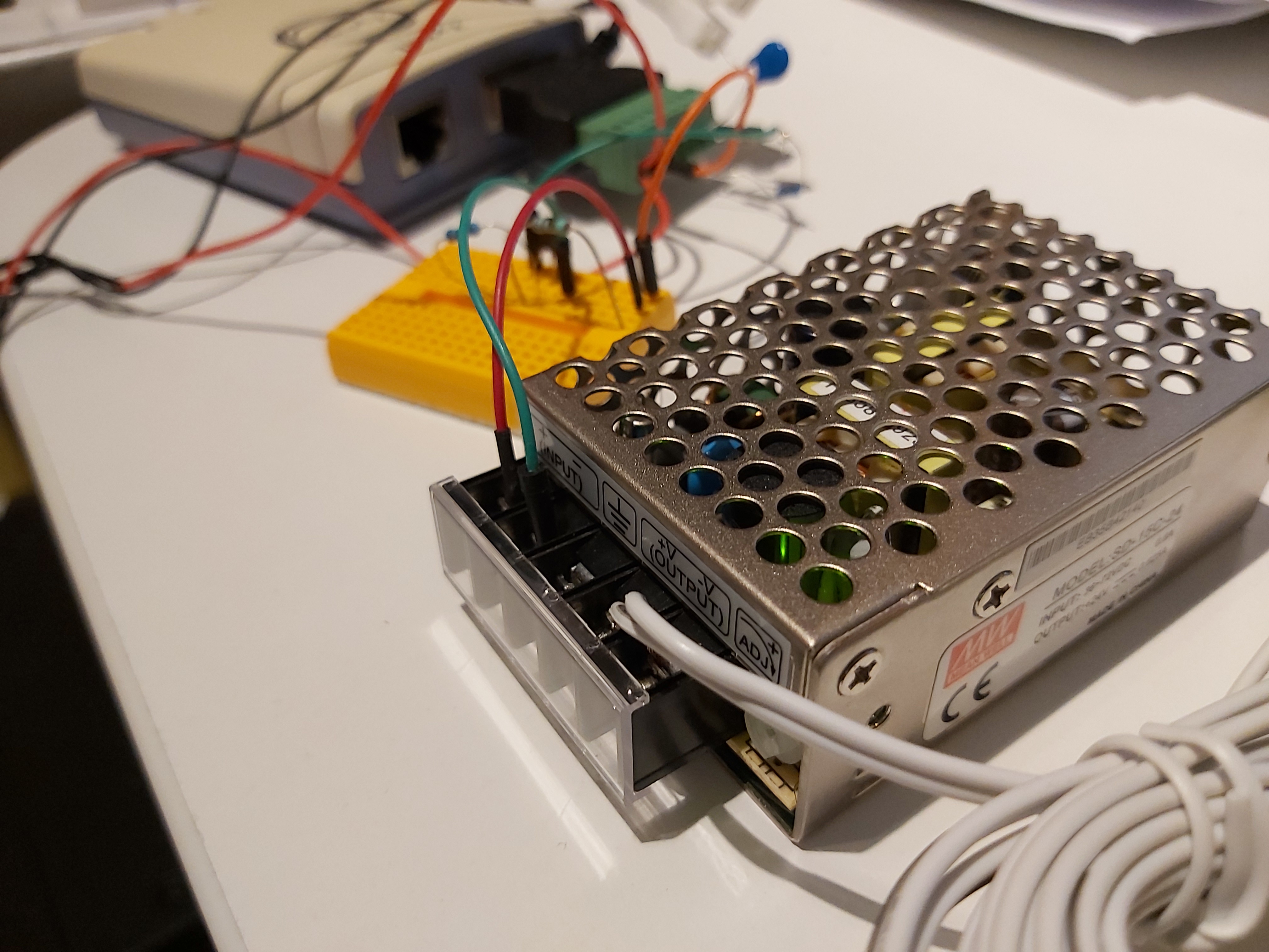
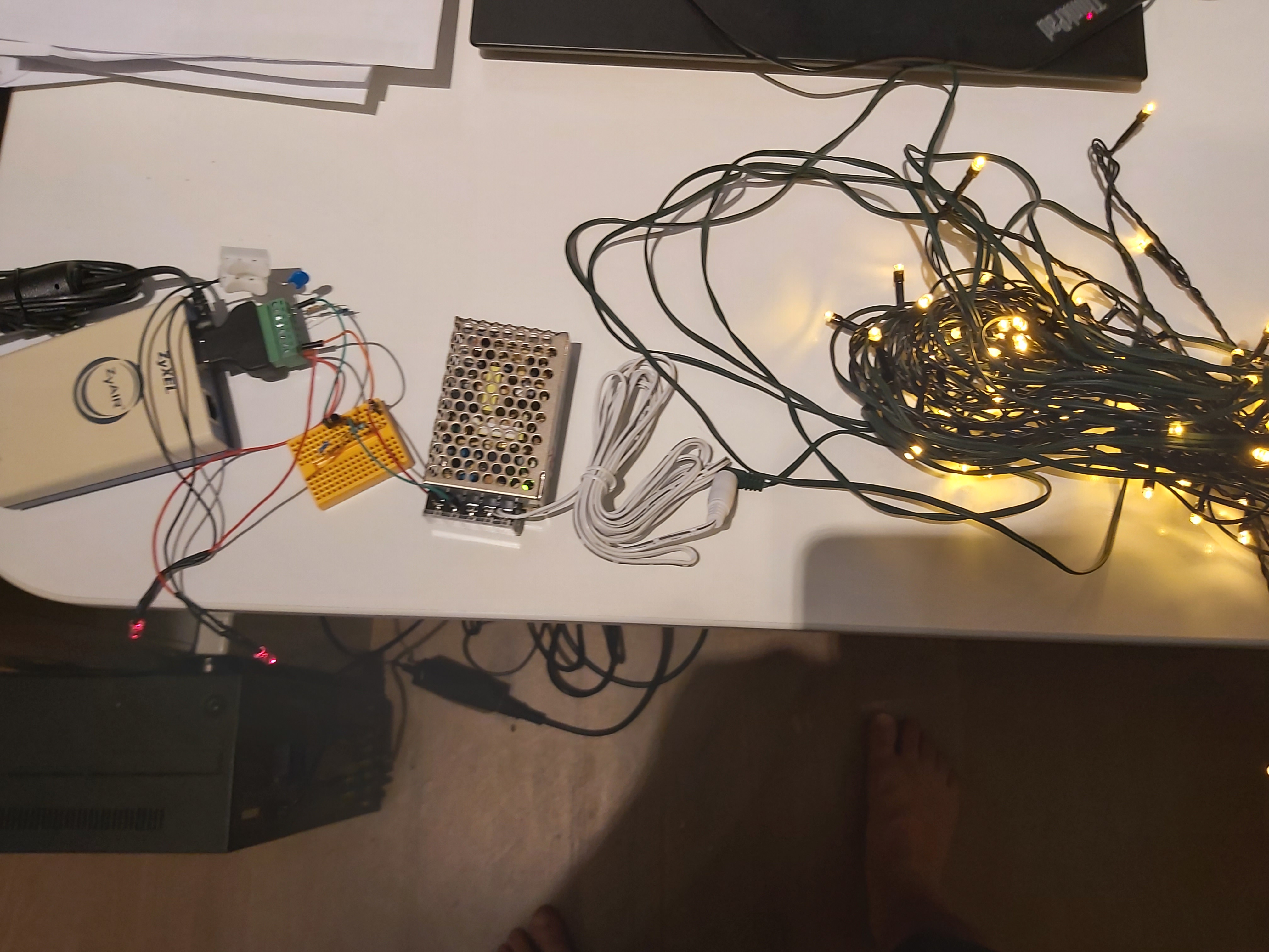
Found some broken LED christmas lights (operated originally from 24V transformer) and a suitable spare switch mode power supply (36-72V to 24V). Then I got an idea to combine them to an experimental PoE Christmas light project.
Circuit diagram:
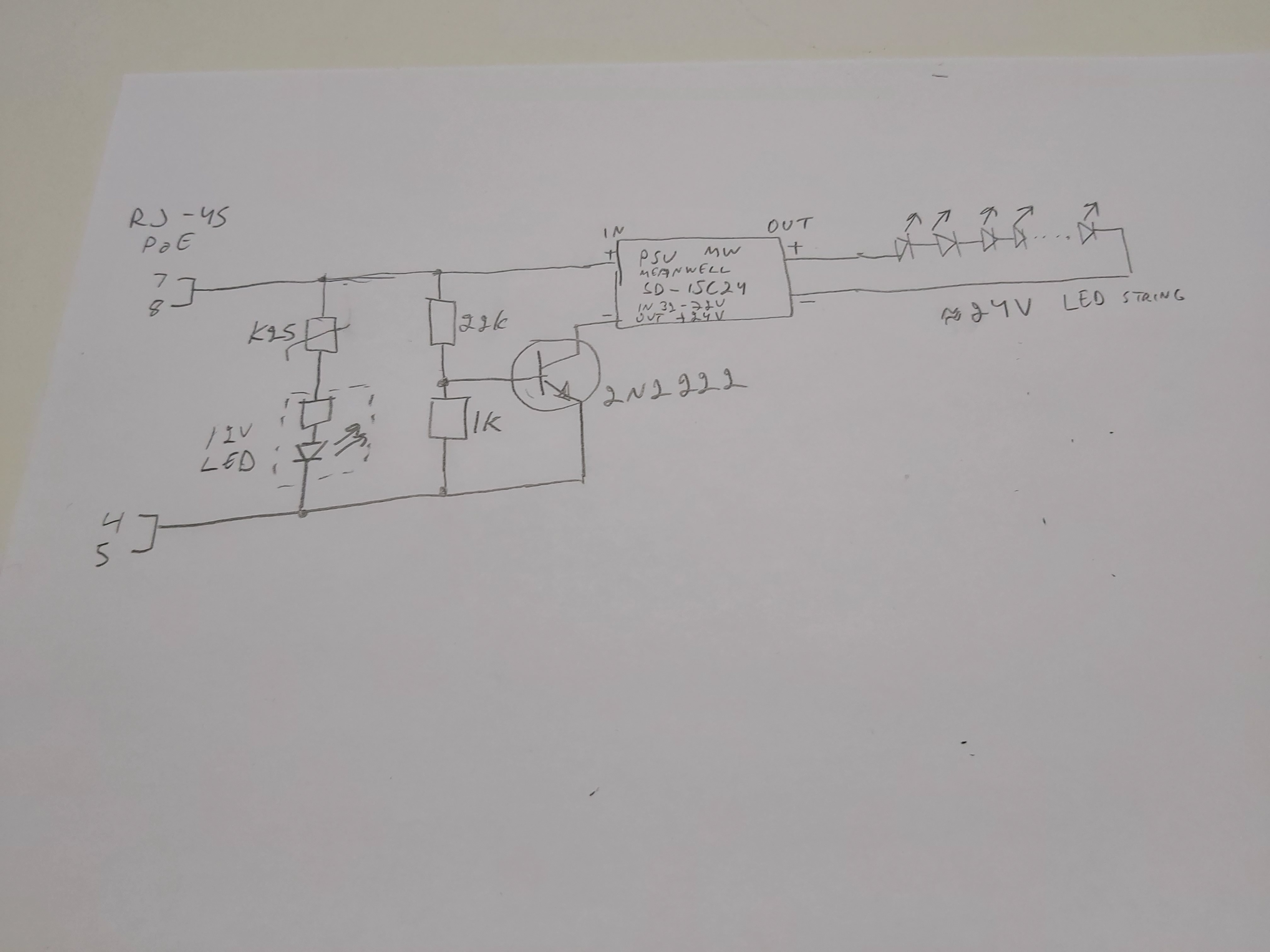
The circuit operation:
Initially circuit presents around 23 kohms impedance when low voltage is on line (PoE PD is expected to be 19-27 kohm at 2.8-10v). Power supplying circuit can detect my load (PD). The 22k and 1k voltage divider keeps transistor off when voltage is 10V or lower.
When PeE power supplying circuit detects PD, it turn on 48V DC to line (+ to 7,8 pins and – to 5,6 pins of RJ-45). When voltage is 48V, the transistor can turn on passing power to the DC-DC converter. My 12V indicator LED will turn on getting it’s power through VDR that that takes around 35V voltage drop.
This was a “quick hack” that worked this time. It is not a reliable circuit recommended for any real application.
12 Comments
Tomi Engdahl says:
Designing Power OverEthernet Using LM5070 andDP83865
https://application-notes.digchip.com/006/6-8978.pdf
“To detect PD device, the PSE applies a DC voltagebetween 2.8V to 10V across the power delivering lines.Based on the loop current, PSE determines if there is a PDconnected. The PD should present a resistive load between19 K to 27 K Ohms with a parallel capacitor 120 nF or less asa signature”
Tomi Engdahl says:
https://www.eetimes.com/simple-circuit-design-tutorial-for-poe-applications/
Tomi Engdahl says:
Links to some other PoE light projects
https://bikerglen.com/blog/ethernet-powered-pixels/
https://fabiobaltieri.com/2013/12/29/power-over-ethernet-flashlight/
Tomi Engdahl says:
POE TECHNOLOGY SIMPLY PUT
https://www.eurodk.com/en/blogs/poe-technology-simply-put
1) First, a test is carried out: whether the connected device is powered (PD). Voltage of 2.8 to 10 V is supplied to it, the input resistance of the connected device is determined. If the settings correspond to the required ones, the power supply device proceeds to the next step.
2) The power supply device determines the power consumption of the connected device, for subsequent control of this power. Depending on the power, devices are assigned a class: from 0 to 4.
Once the device is classified, voltage of 48V with the rising edge of no more than 400 ms is supplied to it, and the power supply device starts to control its operation:
1) If the device consumes less than 5 mA current within 400ms, the power supply is stopped;
2) If the resistance of the connected device is greater than 1980 kOhm within 400ms, the power supply is stopped.
3) If the current consumption exceeds 400mA within 75ms, the power supply is stopped.
There are 3 PoE standards, what is the difference between them?
1. PoE – IEEE 802.3af
The first generation of PoE (IEEE 802.3 af) provides DC power up to 15.4W to each connected device.
2. PoE+ – IEEE 802.3at
The next standard, IEEE 802.3at, provides power up to 30W to each device. Thus, PoE+ is able to supply power to devices with greater capacity, such as Pan-Tilt-Zoom (PTZ) surveillance cameras and high-performance wireless access points 11n.
3. IEEE 802.3bt
Currently, a new standard IEEE 802.3bt has been developed, this technology provides for powering devices up to 51 W with one cable, in this case, all four pairs of category 5 cable are used
Passive PoE
What if you need to connect devices that do not support PoE to your infrastructure? In such cases, Passive PoE technology is used. Its peculiarity is that the power source does not inquire the connected device and does not coordinate its power capacity. The power is merely supplied over the vacant conductors of the twisted pair cable using a PoE splitter.
Cable requirements:
• A four-pair twisted pair cable is required with a category not lower than cat.5e;
• The twisted pair should be copper, not copper-plated;
• The thickness of the conductors is not less than 0.51 mm (24 AWG);
• The conductors resistance should not be higher than 9.38 Ohm/100 m (if more, there will be a large loss of power).
Standards 802.3af and 802.3at characterise the length of the twisted pair cable for PoE as equal to 100m. However, in practice the recommended maximum cable length should not exceed 75m. When using Passive PoE, the cable length should not exceed 60m.
Tomi Engdahl says:
My circuit is designed to be identified as
PoE IEEE 802.3af 15.4 W (class 0)
Does not meet all standard features, for example lacks rectifier diodes from power input.
Should also work with non-standard systems that constantly feed 48V DC.
pert says:
Awesome. Do you have smart lighting with timers circuit design for domestic use?.
Tomi Engdahl says:
From
https://www.ti.com/lit/ds/symlink/tps2370.pdf?ts=1607928472691&ref_url=https%253A%252F%252Fwww.google.com%252F
At low input voltages (1.8 V to 10 V), the TPS2370draws less than 12 μA, allowing accurate sensing of theexternal 24.9-kΩ discovery resistor. At input voltagesbetween 15 V and 20 V, an external resistor sets thelevel of current to be drawn during classification mode.TPS2370 is compatible with current as well as voltagemeasurement schemes for classification. Above 20-Vinput, the classification current is shut off, reducing internal power dissipation
The TPS2370 drives an internal low-side FET forcontrol of the return side of the power path. The internalFET is turned on when the input voltage reaches 40 Vand above. When the input voltage decreases, the FET remains on until the input voltage drops to below 30 V.
Tomi Engdahl says:
https://www.veracityglobal.com/resources/articles-and-white-papers/poe-explained-part-2.aspx
Power over Ethernet is injected onto the cable at a voltage between 44 and 57 volts DC, and typically 48 volts is used. This relatively high voltage allows efficient power transfer along the cable, while still being low enough to be regarded as safe.
This voltage is safe for users, but it can still damage equipment that has not been designed to receive POE. Therefore, before a POE switch or midspan (known as a PSE, for power sourcing equipment) can enable power to a connected IP camera or other equipment (known as a PD, for powered device), it must perform a signature detection process.
Signature detection uses a lower voltage to detect a characteristic signature of IEEE-compatible PDs (a 25kOhm resistance). Once this signature has been detected, the PSE knows that higher voltages can be safely applied.
Classification follows the signature detection stage, and is an optional process.
If a PD does not display a signature, it is class 0 and must be allocated the maximum 12.95 watts.
The final stage after detection and classification of a newly connected device is to enable power: the 48V supply is connected to the cable by the PSE so the PD can operate. Once enabled, the PSE continues to monitor how much electrical current it is delivering to the PD, and will cut the power to the cable if too much, or not enough, power is drawn. This protects the PSE against overload, and ensures that POE is disconnected from the cable if the PD is unplugged.
Tomi Engdahl says:
Navigating the IEEE 802.3af Standard for PoE
https://www.powerelectronics.com/content/article/21858350/navigating-the-ieee-8023af-standard-for-poe
802.3af standard (available at http://www.ieee.org). Briefly, the PoE link allows a powered device (PD) to draw up to 12.95 W from the power-sourcing equipment (PSE). The PoE link or port is controlled by the PSE, which identifies PDs via detection and classification before powering and monitoring the port (ICUT, ILIM and disconnect).
During classification, the PSE must maintain an output between 15.5 V and 20.5 V, so it can measure the PD’s classification signature and determine how much power the PD needs. A bad classification measurement or a faulty power allocation scheme can overload the PSE and bring the whole PoE network down.
bypass capacitance must be less than 0.52 µF
Perhaps the biggest enemy of classification stability is the PD. The 802.3af standard only requires the PD to draw current to meet one of the five classes. A PD may draw little current until the port voltage enters the 14.5-V to 20.5-V classification range. At this point, the PD can throw a switch and instantly load the port with up to 44 mA (Class 4).
The standard says nothing about PD current between detection (10.1 V) and classification (14.5 V) and between classification (20.5 V) and power on (30 V). A PD that draws no current in these ranges may take a long time to be detected, because the PSE isn’t required to actively discharge the port and only leakages will discharge the port in these ranges.
In these two undefined regions, the PDs should roughly stay within these limits: PDs should draw more current than a 25-kΩ resistor and less current than their classification signature
What does this mean for a Class 0 PD where the classification signature may be 0 mA? The answer is simple: Don’t build a Class 0 PD.
Classification is optional. However, customers will expect classification because devices without classification waste power and thus waste their money.
While classification makes better use of the PSE’s available power, the 802.3af standard still emphasizes reliability over efficiency. A PSE can never allow itself to become overloaded.
Power On
Turning power on is the real test of a PD design, as the PD must prevent port voltage oscillations. At a port voltage between 30 V and 42 V, the PD must turn on, which generally means connecting a hefty input bypass capacitor to the port. The combination of the large capacitor and the PSE’s current limit can cause the port voltage to drop below 30 V, even to 0 V. If the PD turns off because of a drop in the port voltage, it will begin toggling between on and off. A PD design can guard against motor boating by limiting its current to keep the port voltage in the powering range or the PD can allow the voltage to drop but maintain its powered-on state for a limited amount of time, regardless of the port voltage.
Depending on the response time of its 48-V supply, a PSE will need 50 µF to 300 µF per port. Each port should have 0.1 µF to 0.52 µF of capacitance at its output. To ensure high-frequency stability, this local bypass should have low ESR.
Sensing the removal of the PD and turning off power, what the IEEE calls “disconnect,” is as important as the decision to apply power. In either case, the consequences of a mistake are the same: damaged equipment.
DC disconnect, which relies on measuring the port current to determine the PD’s continued presence, is simple in concept and implementation.
AC disconnect senses the presence of the PD with a low-frequency ac measurement of the port impedance.
AC disconnect must sense the impedance of a PD at the far end of the Ethernet cable while simultaneously providing a stable output voltage to power the PD.
If the ac disconnect circuitry is not designed properly, microamp-level leakages will be sufficient to keep the port on.
In addition to turning the port off when the PD is unplugged, the PSE must remove power due to fault conditions such as excessive port current.
While the standard allows PSEs a leisurely 1 ms to bring their outputs into the 400-mA to 450-mA ILIM current limit, carefully designed PSEs will operate much faster, quickly limiting the energy during a fault condition.
If a short occurs at the end of a 1-m to 10-m cable, the cable inductance does little to slow the rapid increase in current, which can exceed 10 A within 100 µs, storing an appreciable amount of energy in the cable’s magnetic field. When the PSE attempts to limit the current, the cable responds to reduced current by unleashing its stored energy and applying what could become kilovolts to the PSE. At the very least, PoE devices should include unidirectional surge suppressors on each port. Additional features, beyond the scope of the 802.3af standard, can aid in managing fault conditions. The fast pull-down circuitry included in Linear Technology’s LTC4258 and LTC4259A PSE controllers turns off the port in less than 2 µs if the current exceeds 600 mA.
The standard is clear about what the PSE should do in response to fault conditions. However, the standard does not cover abnormal conditions, such as changes in the PSE’s output voltage. A PSE’s output voltage might change by 10 V when PDs are plugged or unplugged or the PSE switches to a redundant 48-V supply. These output changes are permitted as long as the slew rate is kept under control.
The 802.3 standard requires all Ethernet ports to be electrically isolated from any other conductor that is user accessible.
Some PD applications such as wireless access points with built-in antennas don’t need user-accessible connectors beyond the RJ-45. For PDs that need other external connectors, the isolation problem is solved by dc-dc converters without a galvanic connection from input to output.
Tomi Engdahl says:
PoE Technology Simply Put
https://www.eurodk.com/en/blogs/poe-technology-simply-put
Elegante Elegante says:
Thank you very much for sharing such a useful article.
Best Home Automation in hyderabad
mydesert says:
it looks good article
regards
mydesert