DMX stands for Digital Multiplex DMX512 (Digital Multiplex) is a standard for digital communication networks that are commonly used to control stage lighting and effects. DMX can now be used to control almost anything, reflecting its popularity in theatres and venues. I have some DMX-512 controlled lights and also built some DMX-512 hardware myself.
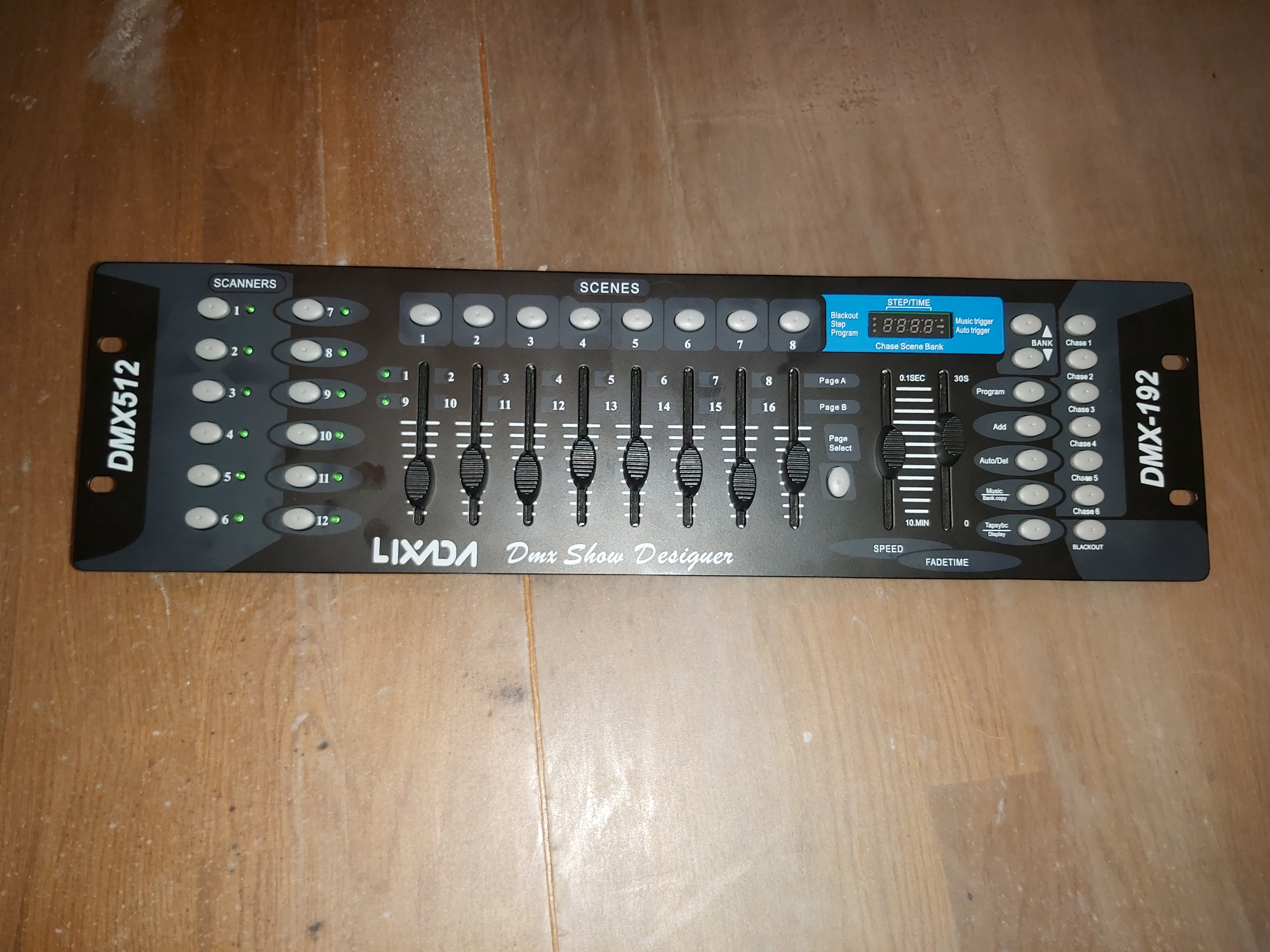
I have used some computer controls and some very simple desks for light controlling earlier. There have been times where I have wanted to have a programmable DMX-512 desk with at least eight sliders that would not cost to much. I saw Lixada 192 Channels DMX512 Controller Console for Stage Light Party DJ Disco Operator Equipment for sale at very low price (below 30 Euros). So it looked like an attractive deal especially as this type of desk is widely sold under various brands. It might not be the best, but could be at least half-decent and useful. I looked some videos on YouTube, and based on them it looked OK.
I finally got the desk and it looked OK and buttons seemed to work.
Then I started testing using the manual and some introductory videos like this.
DMX 192 Controller Unboxing and Programming
I did lot’s of testing. The controls seems to work, but I was unable to get any of my DMX-512 equipment to work with it. It seems that there is no signal coming out of the back of the unit no matter what I did. I even measured the signal coming from the back of the unit, and did not get any consistent results, sometimes no signal at all, sometimes only from either pin 2 or 3. Not valid RS-485 signal levels. My DIY DMX signal tester did not show any useful signal. I also tested signal with multi-meter and oscilloscope.
I got money back after I posted them a video how their board does not work and it should. They did not want their crap back, so I got to keep the non-working device. Next task was to open device to see what is inside it and maybe even fix it.
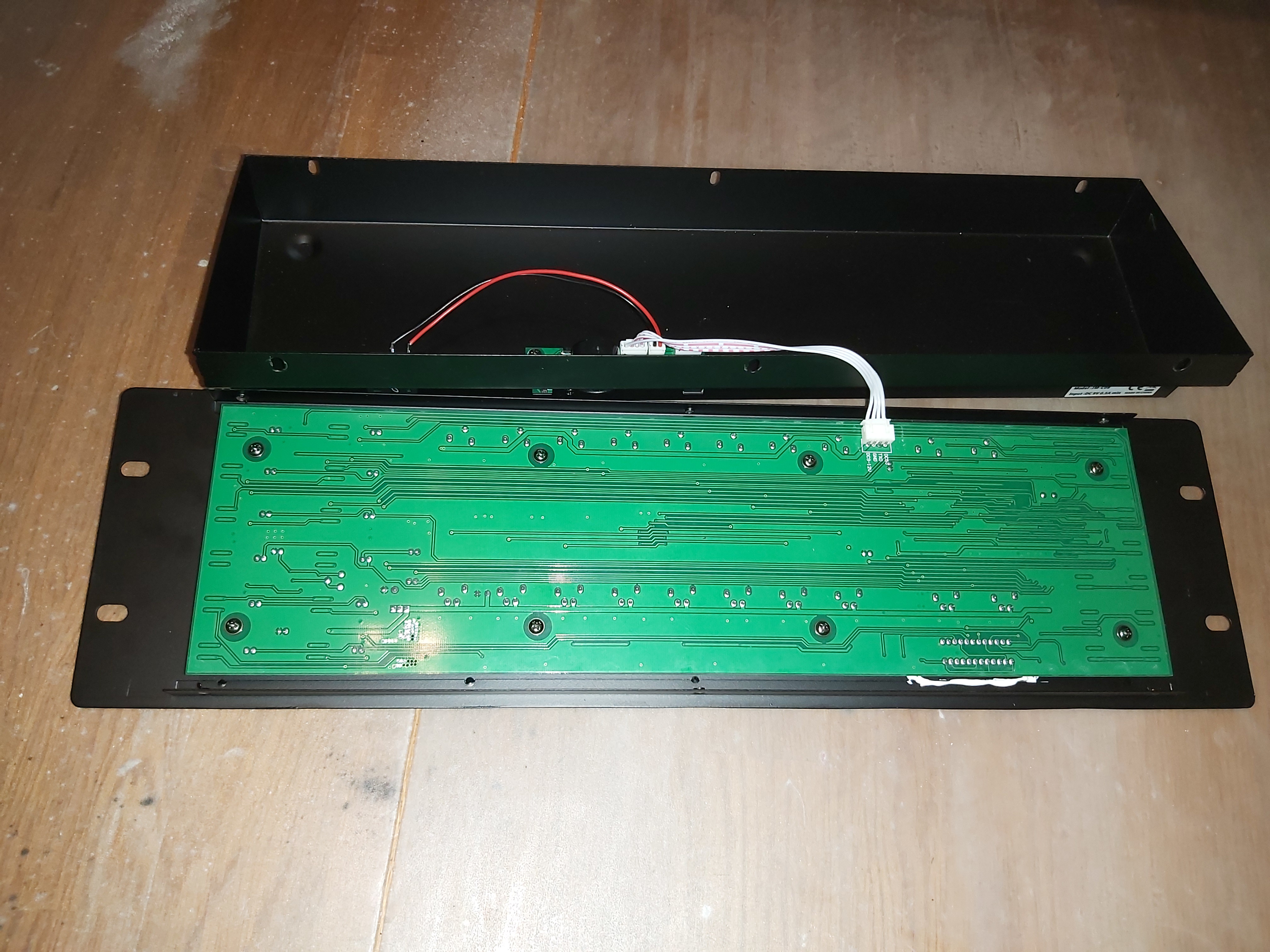
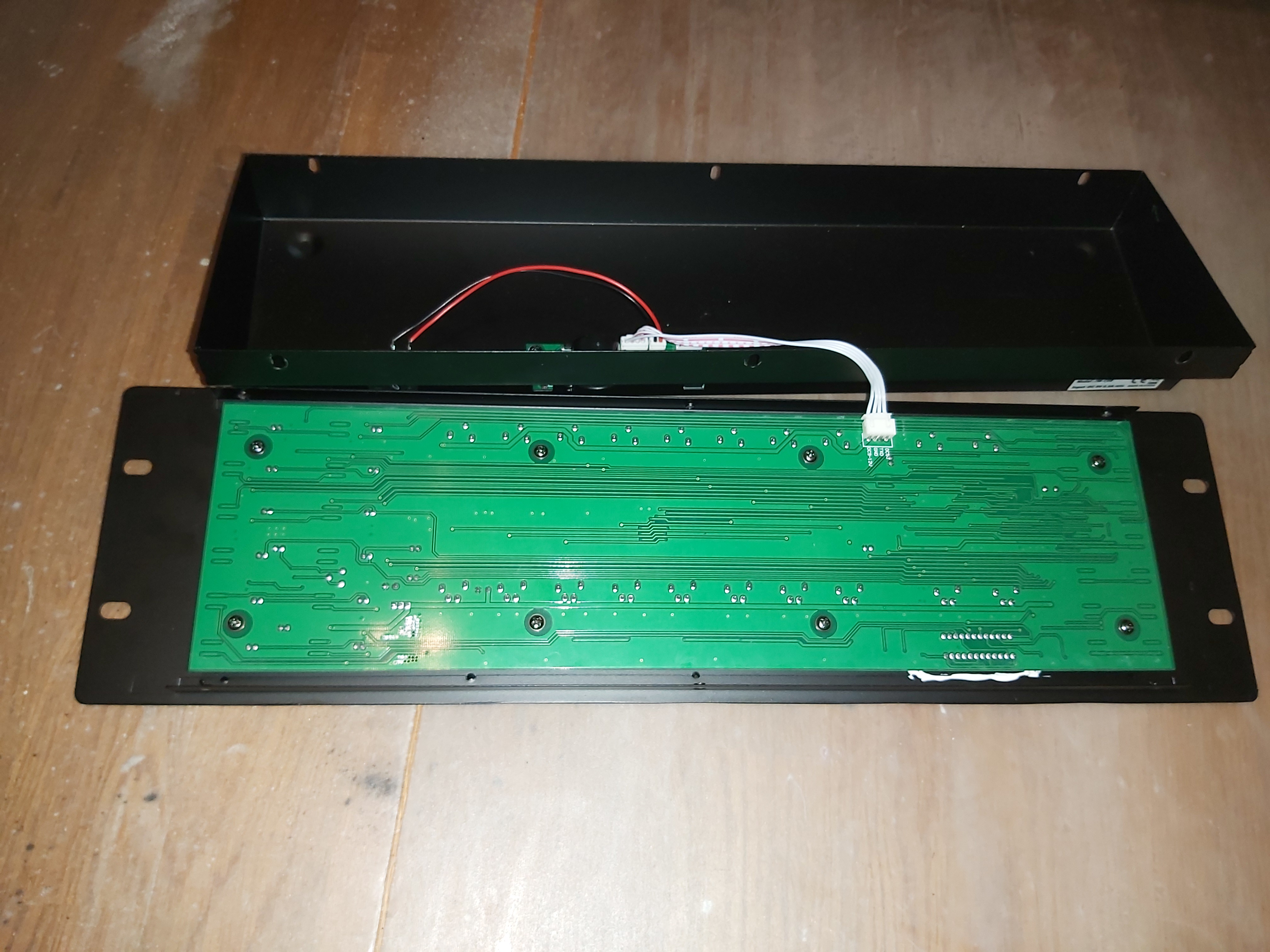
The bog circuit board has all the controls and the “brains”. There is a smaller IO board that has connectors. There is four wire cable between them that carries 9V power in, 5V power, ground and transmitted data.
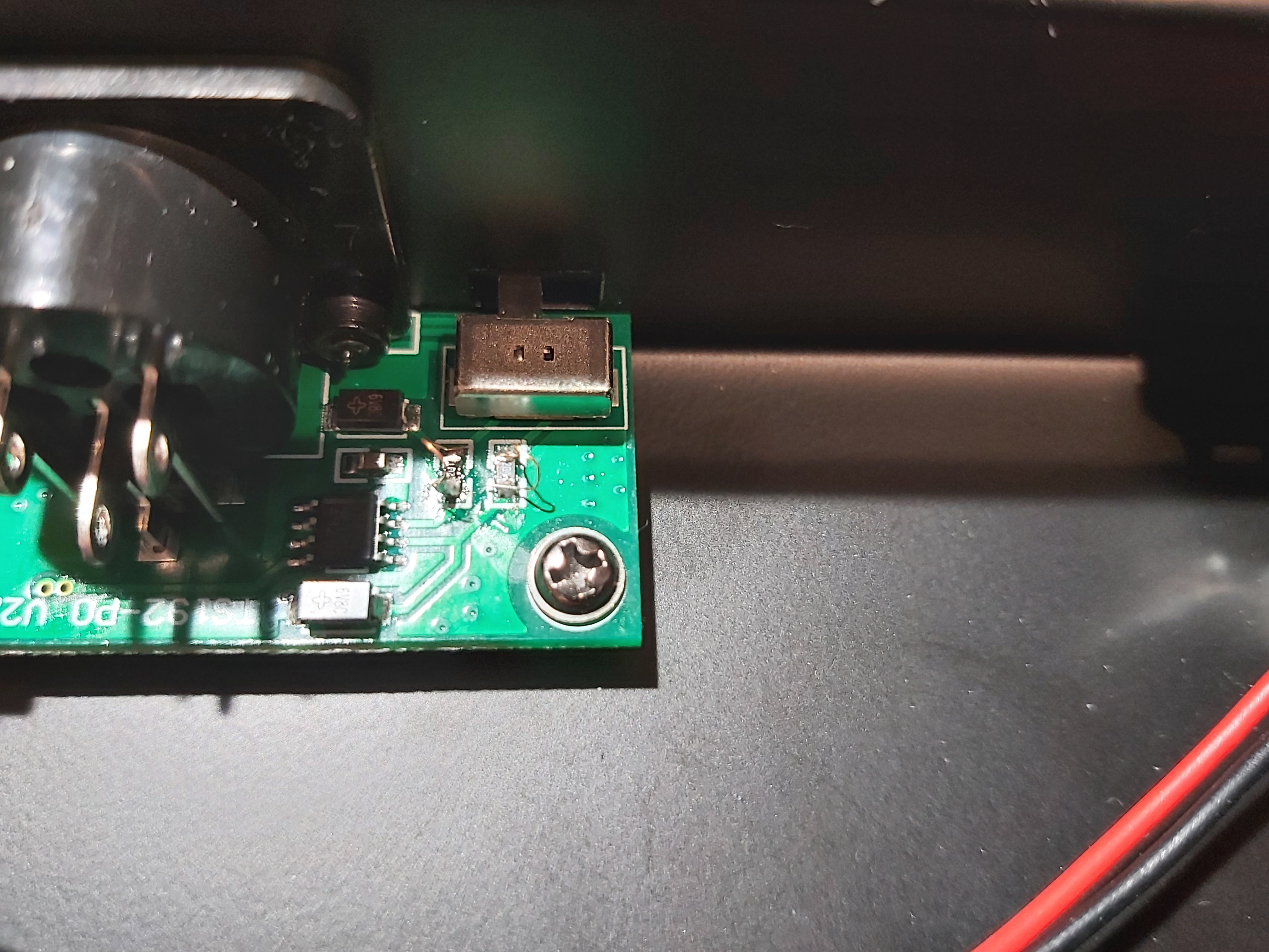
Here is a closer look at connectors board. It seems that the problem could be somewhere here.
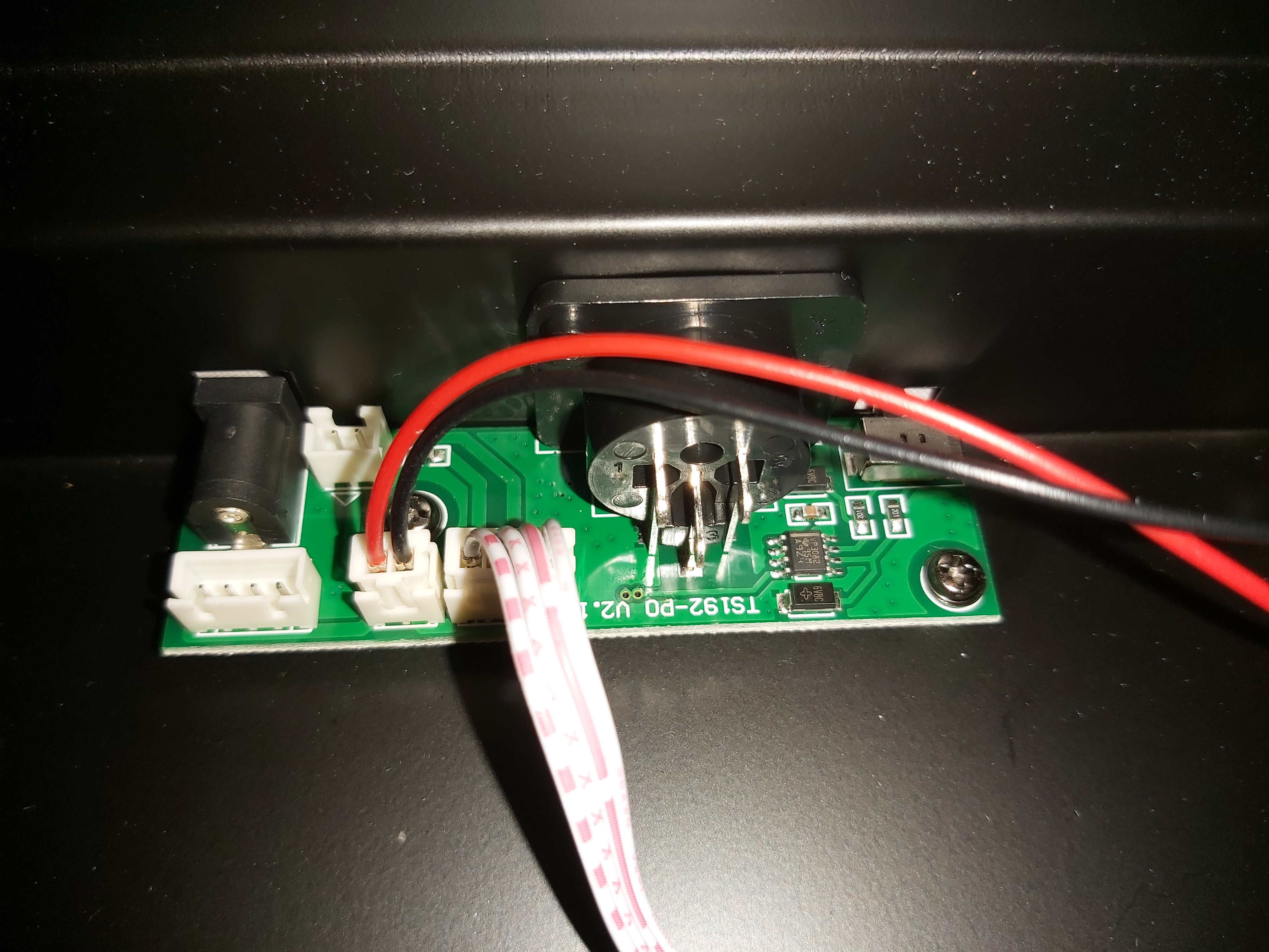

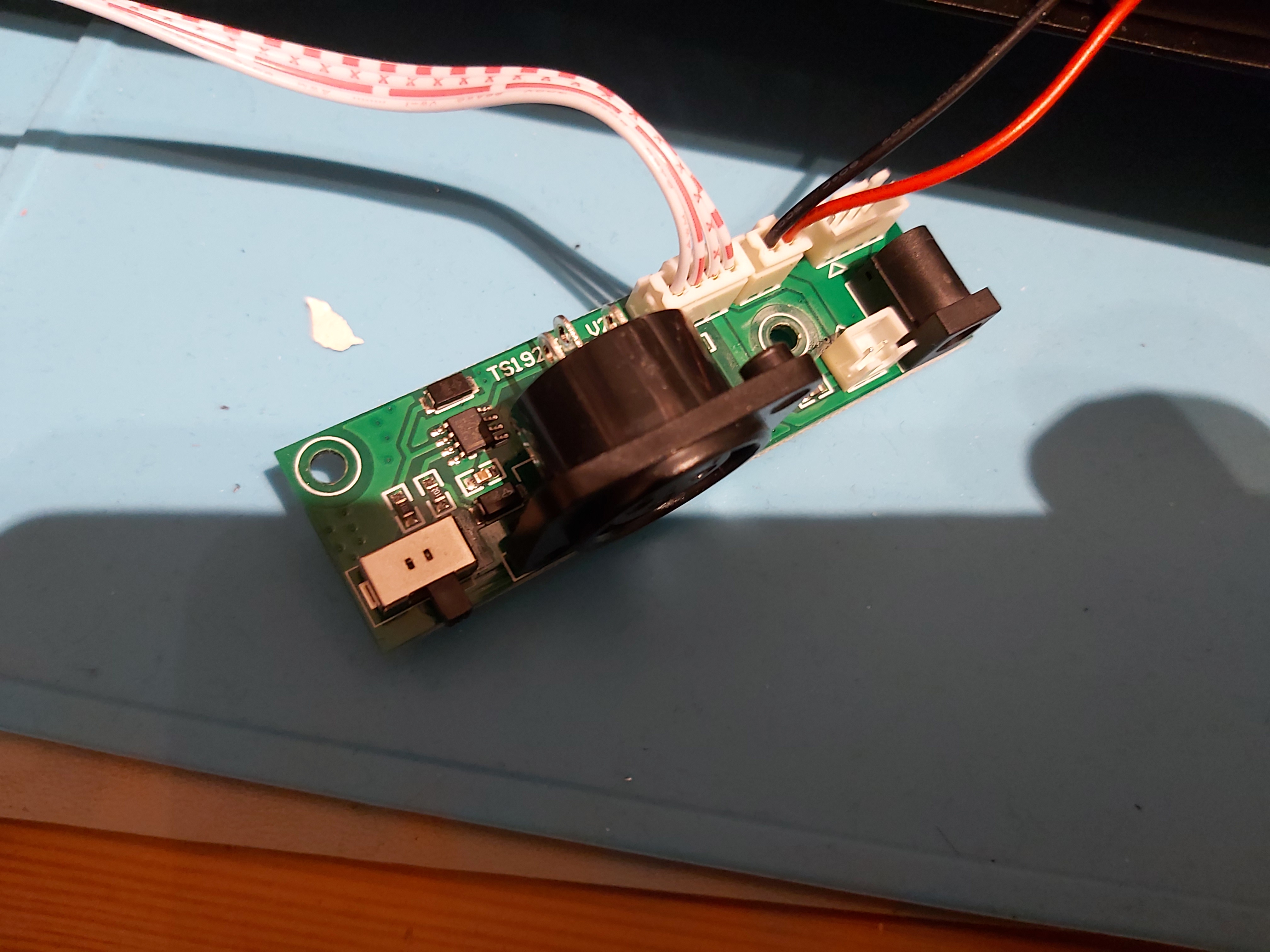
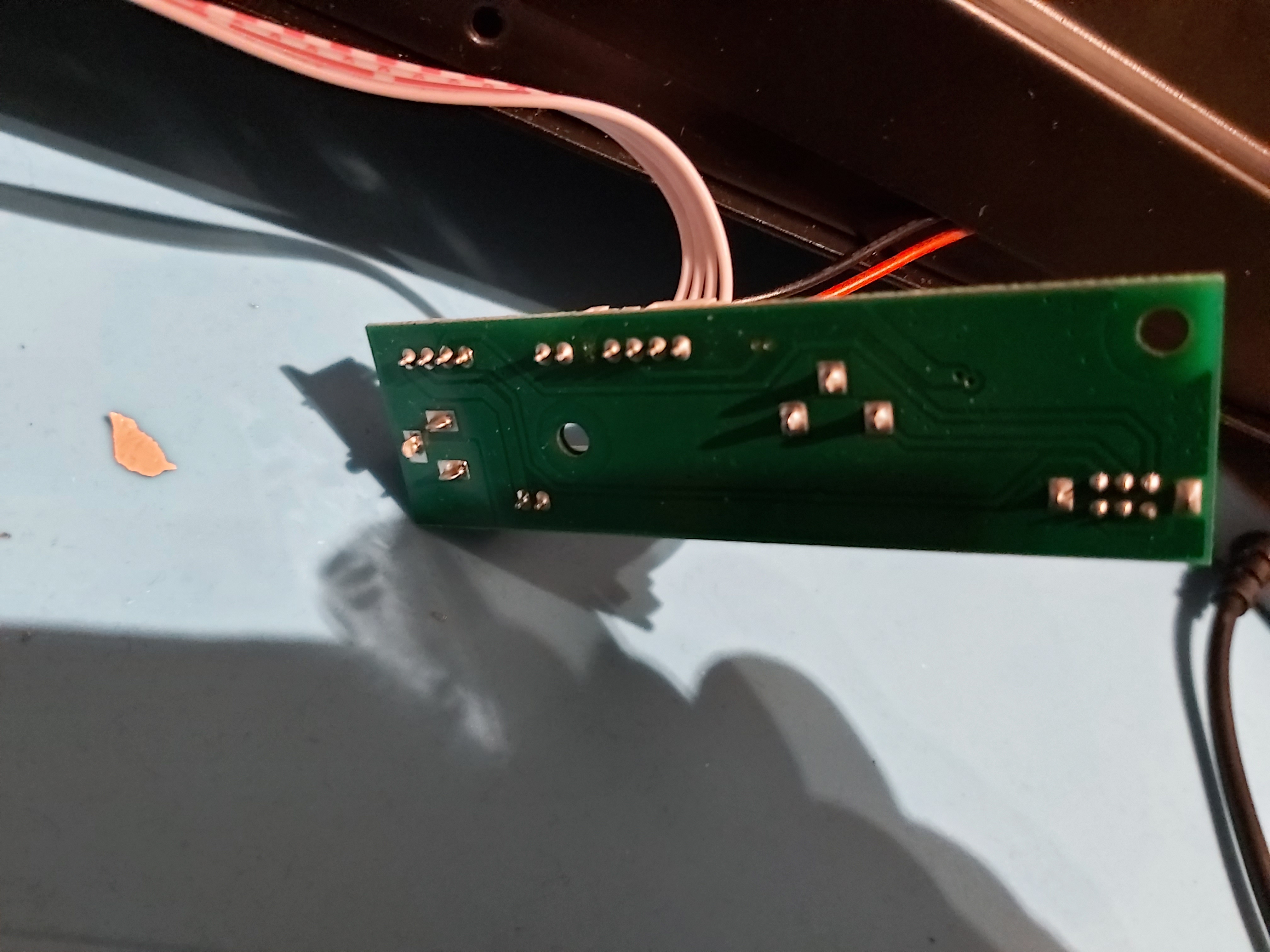
Problem seems be that this board does not seem to not work.. The board is pretty simple with RS-485 line driver chip, some other components and connectors. A quick probing seems to indicate that the RS-485 driver works OK, but the signals for some reason did not get to output connector properly.
Looked what would be problem by more probing the circuit, trying to look what goes where, try to look component codes and measure passive component not clearly marked. After some probing I draw this basic idea how the DMX-512 driver output works. There seems to be some over-voltage protection components and some series resistors to connector.
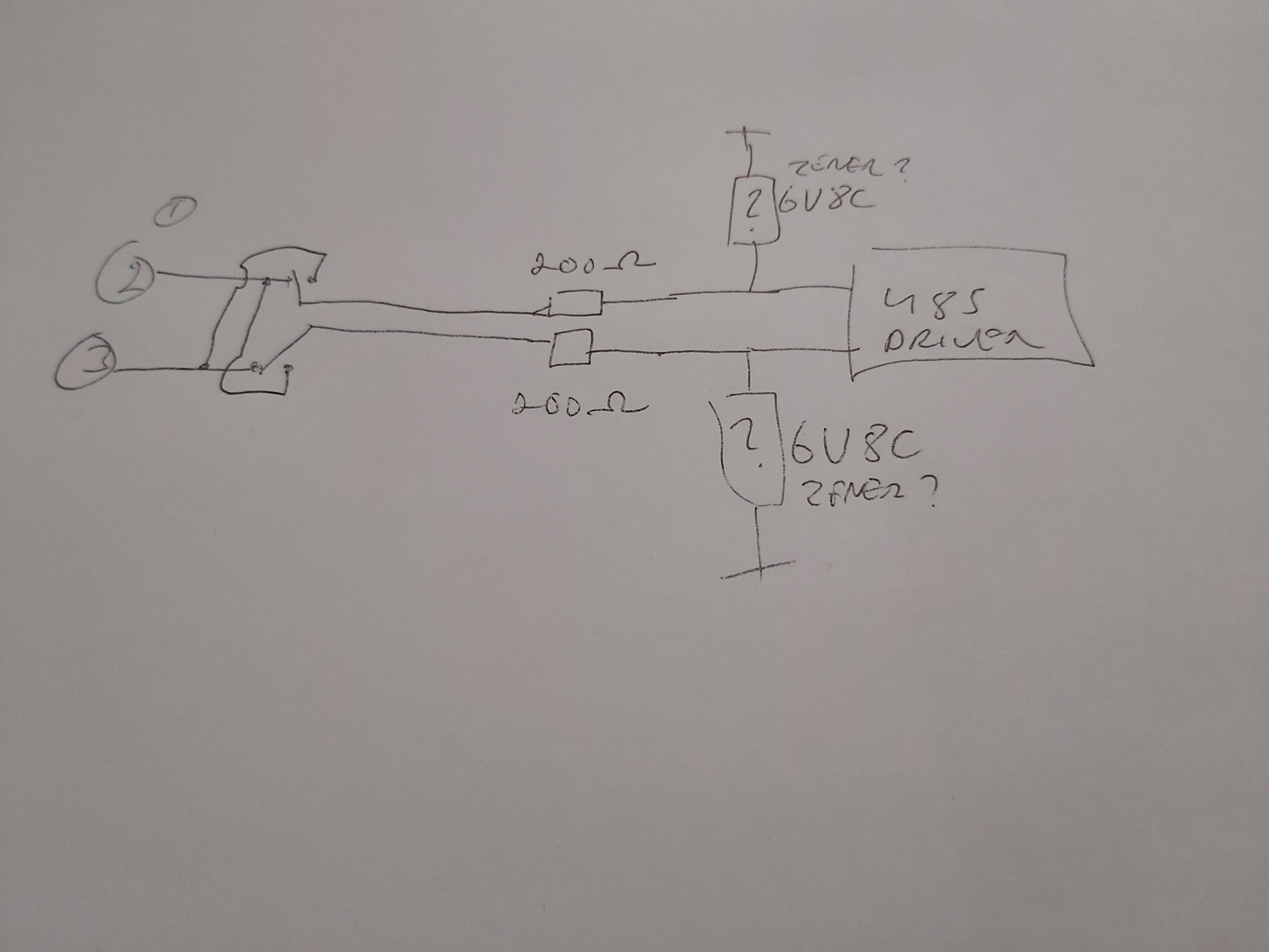
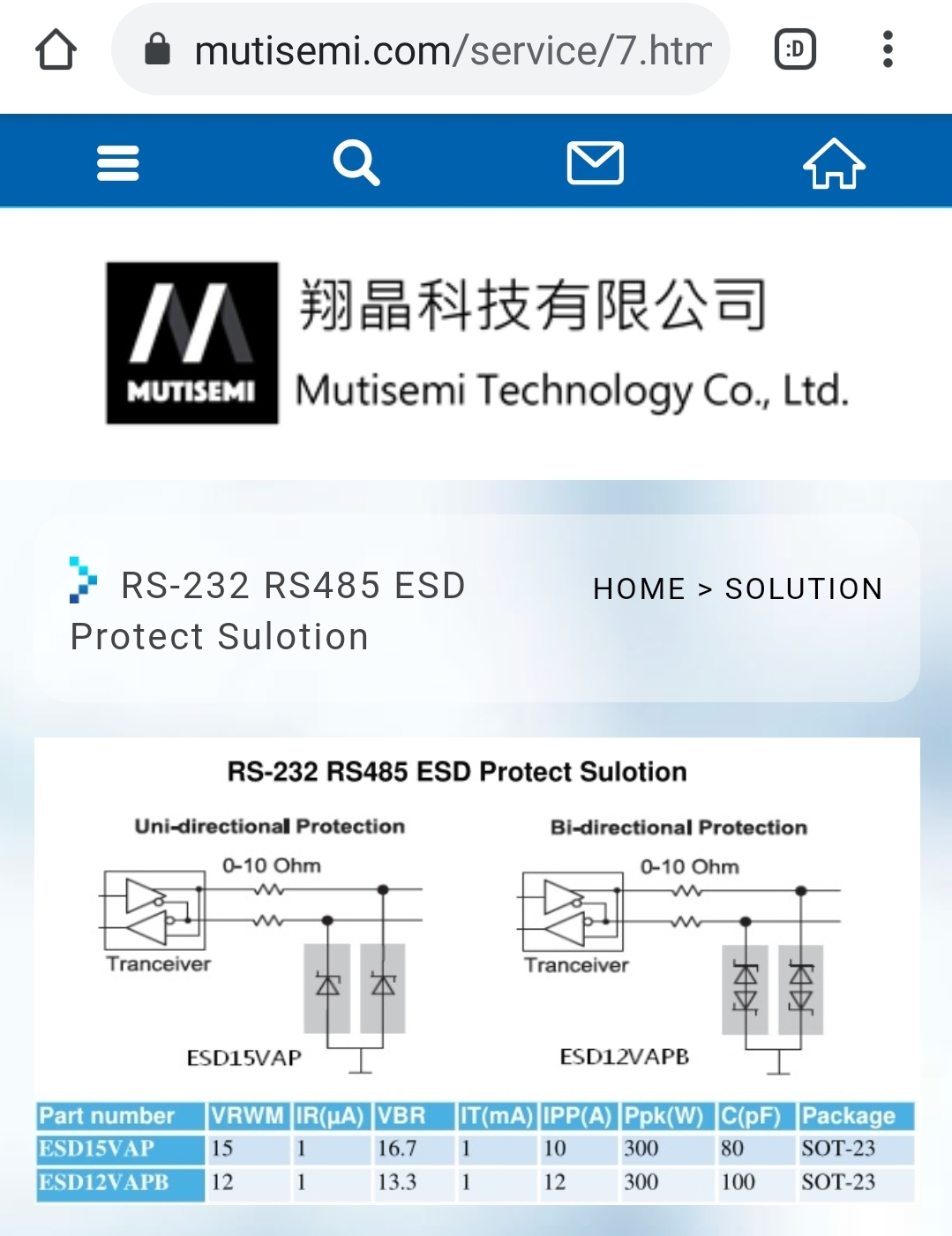
Based on my fault-finding it looks like there is completely wrong resistor values compared to what they should be. Those two 200 ohm resistors will pretty much screw up the output impedance matching and cause signal to be attenuated a lot when the DMX-512 line is properly terminated with 120 ohm resistor. Those series resistors if they are used should have much lower in value to no cause issue. For example in this mutisemi application example picture those resistors are 0-10 ohms:
Finally I tried a fix with short jumper wires over those 200 ohm resistors bringing them close to 0 ohms.
After this modification I got the board to work nicely. It worked with the light I had, bot with and without DMX-512 terminator on the line. The board worked nicely with quite long cables as well (100 meters of CAT 5E UTP). So this fix made the board to work well. I think that there has been some manufacturing error on the factory that made this product so that they had put wrong value resistor to the board and for some reason the product testing did not catch this error for some reason. The potential downside of this modification is that the surge protection on the DMX-512 output might not be as effective as it was originally designed to be (small resistors between connectors and zeners will absorb surge energy more than short circuit before it hits the zener diodes and the driver chip).
On the basic tests the board seemed to work well. I have not tested all the board features. I am planning to view again some more videos on using the board to learn how to use it well:
How to Program DMX lights – SCENES CHASES & BANKS w Rockville ROCKFORCE 192
Lumin Lights 192 DMX Controller Mixer Mixing Board Light Controller
How to program DMX lights for beginners (simple lesson)
17 Comments
Tomi Engdahl says:
Make Your Own DMX Signal Tester
https://www.youtube.com/watch?v=wLC3ojYHd70
DIY keychain DMX tester for lighting technicians.
https://www.youtube.com/watch?v=skwUNRp-Rrk
Tomi Engdahl says:
How to make a DMX Terminator with built in Tester
https://www.youtube.com/watch?v=tdSK5coyvvc
Tomi Engdahl says:
I once considered building something like this before I go my hands on this very cheap light control desk…
Arduino DMX 512 Tester and Controller ENG
https://www.instructables.com/Arduino-DMX-512-Tester-and-Controller-ENG/
Control tool for testing and light show by the DMX-512 protocol, ideal for quick tests on fixed or temporary installations of lighting. This project arises from the need to have a portable system for rapid testing in lighting installations, without the need to install lighting consoles, interfaces or computers in environments outside, hostile or difficult to access.
Arduino DMX-512 Tester Controller © GPL3+
Control tool for testing and light show by the DMX-512 protocol, ideal for quick tests on fixed or temporary installations of lighting.
https://create.arduino.cc/projecthub/daniel3514/arduino-dmx-512-tester-controller-977c89
Tomi Engdahl says:
Did something like this happen on the manufacturing?
Fail Of The Week: Mistaking Units For Values
https://hackaday.com/2021/04/24/fail-of-the-week-mistaking-units-for-values/
Tomi Engdahl says:
http://joat-mos.blogspot.com/2014/01/repairing-dmx-lighting-controller.html
Tomi Engdahl says:
No real life mic cable you can buy has really 600 ohms impedance. Practical mic cables have typically impedance in 40 ohms to 150 ohms range.
“Standard analog audio cable impedance is 45 Ohm to 70 Ohm.”
Source: https://beldencables-emea.com/en/products/pro-broadcast-products/audio_cables/index.phtml
Tomi Engdahl says:
DMX (and AES) cable is 110 ohms.
Not a serious problem to interchange with mic cable on very short runs, but long runs/lots of cables jumped together causes problems
Tomi Engdahl says:
“in a pinch you can definitely use short runs of three pin xlr and mic cable in place of DMX type 5 pin.”
Yes.
“Regular mic cable has basically no insulation and DMX is very susceptible to interference….”
I have to disagree somewhat with this. Normal mic cables have typically quite good insulation and good shielding – in many ways ok for DMX.
The most serious problems are typically related to wrong cable impedance (causes signal attenuation and bit errors on long runs). Sometimes the cable insulation materials can cause extra signal attenuation. And ground loops can cause issues.
Tomi Engdahl says:
https://propaudio.com/wp-content/uploads/2019/02/5-pin-female-to-3-pin-male-DMX-adapter-cable-Wiring-diagram.jpg
Tomi Engdahl says:
How the cheap wireless DMX boards use the NRF24L01 protocol
https://oscarnet.eu/how-the-cheap-wireless-dmx-boards-use-the-nrf24l01-protocol/
Tomi Engdahl says:
DMX 192 Controller Unboxing and Programming
https://www.youtube.com/watch?v=zyV1CjHoJ2U
How to program DMX lights for beginners (simple lesson)
https://www.youtube.com/watch?v=dJQAZsNwcv4
Tomi Engdahl says:
CO-Z 192 DMX Controller – A review, demo and how to start creating DJ Light Shows w/o over spending.
https://www.youtube.com/watch?v=DetjcLviGAg
Tomi Engdahl says:
So You Want To Get A DMX Board For Under $50 – CO-Z 192 review
https://www.youtube.com/watch?v=QynCoLUkQHc
How to Program DMX lights – SCENES CHASES & BANKS w Rockville ROCKFORCE 192
https://www.youtube.com/watch?v=jFIKWoPcZGI
Tomi Engdahl says:
How to program DMX controller 512 for beginners
https://www.youtube.com/watch?v=zyV1CjHoJ2U
Tomi Engdahl says:
Battle of The Moving Head Lights – Comparing 12 Movers – DJ Gear Review
https://www.youtube.com/watch?v=-SVVTm6RWg8
Tomi Engdahl says:
Typically you have 3 names to identify an intensity only fixture:
Channel
Address
Circuit
Channel is what you use to program the fixtures in the board, its the most arbitrary, dependent on the show.
Address is the DMX position in the chain to control the unit. 1 to 512
Circuit is what is used to identify physical wiring in a rack. If you have a 24 way dimmer rack, Circuit will be 1 to 24, and may include the name of the rack
Sometimes DMX Address is 1 to 1 with the Circuit of the rack.
In more complicated designs, the circuits have individual DMX addresses, to balance loads more efficiently, or group dimmer outputs in more logical patterns.
It depends on your rack whether you can only set a starting DMX Address, so the circuits have to be in direct DMX order; or if your circuits can have different DMX Addresses per Circuit.
A DMX Universe (1 DMX wire) holds 512 DMX channels, with each channel consisting of 255 steps. A lighting fixture can consist of multiple DMX channels, with the first channel being the fixture’s DMX address within those 512 DMX channels. A dimmer typically refers to the amount of light projected in terms of brightness, and often is set to a fader on a console. Faders can also consist of just about any scenes that the programer desires depending on the DMX software/hardware being used, so in short, it just really depends.
Tomi Engdahl says:
The Truth About Lighting Controls
https://www.youtube.com/live/n1j1lxGEnbk?si=GzwLnR4MNuQSSy2-&fbclid=IwZXh0bgNhZW0CMTEAc3J0YwZhcHBfaWQMMzUwNjg1NTMxNzI4AAEexeYITKCdqCVi0_fPpMAeenC-AZyak1M2_mZUw0JCXiNbRjlfxKbOKPyosNI_aem_6fTQfxNduoIrsswDLOYGPg