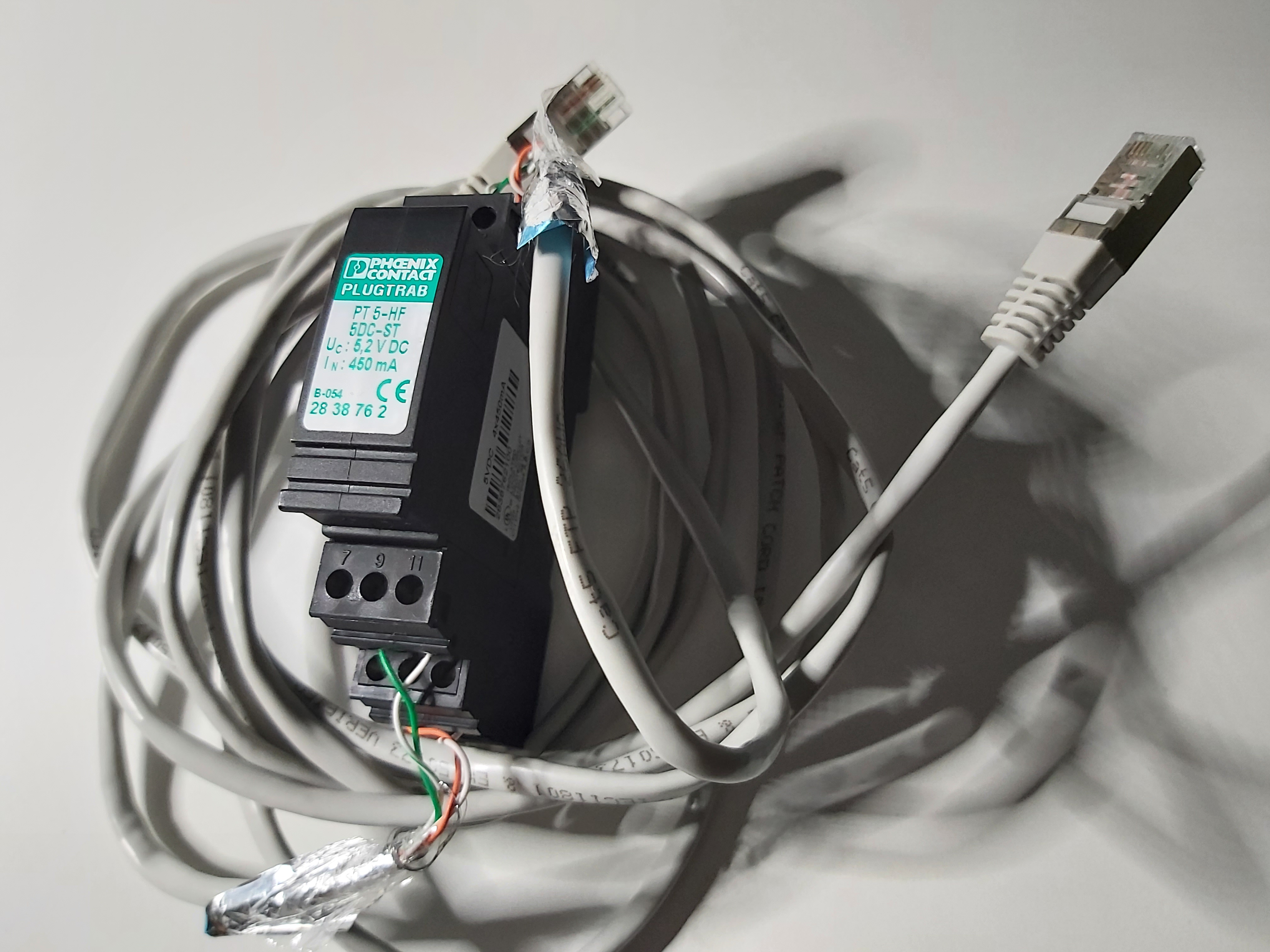
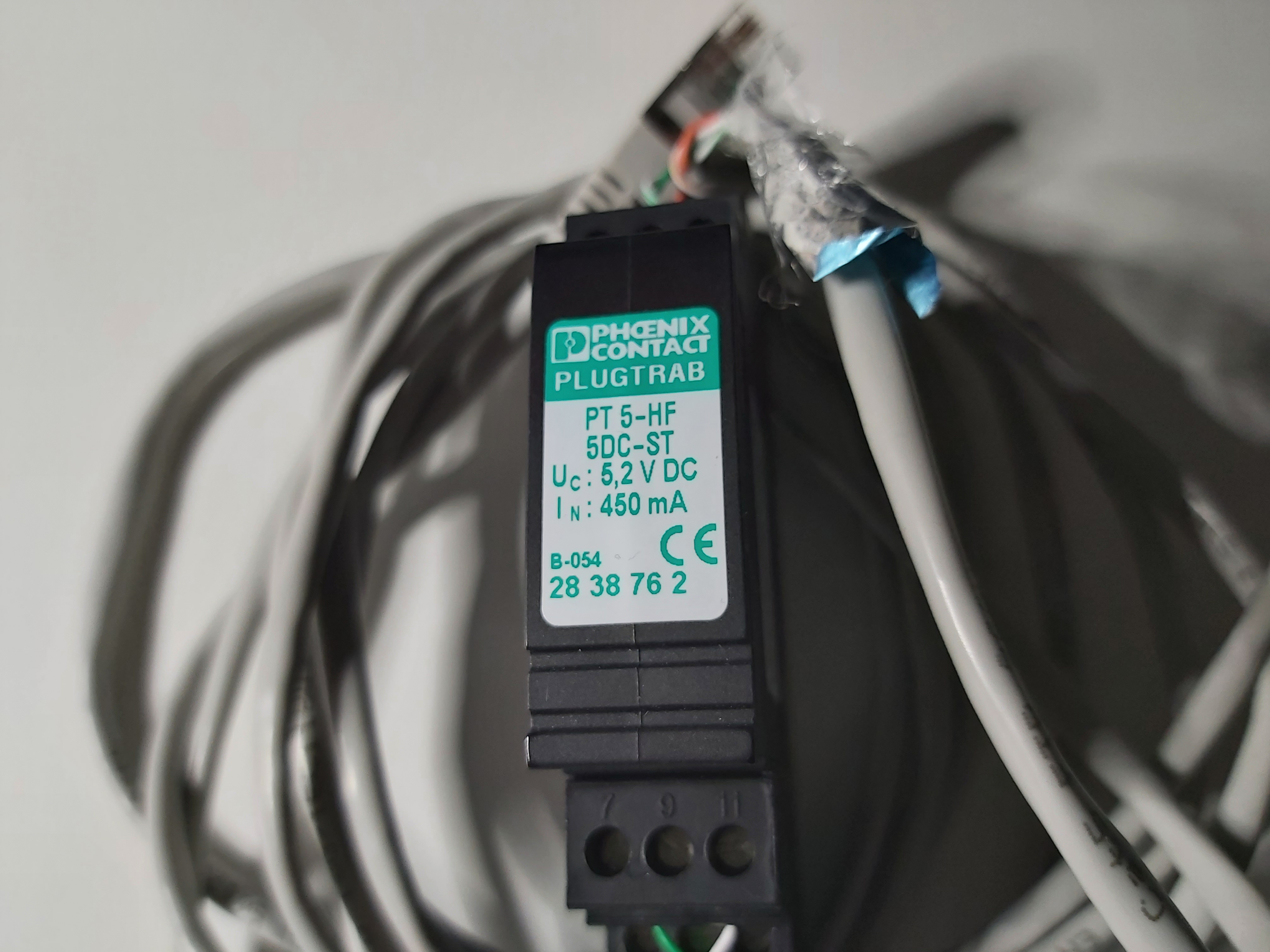
I got 10BASE-T and 100BASE-TX Ethernet running through this over voltage protector. They are nor designed for faster data rate.
Those protectors are designed to protect two 100 ohms wire pairs. They are designed to work well up to 60 MHz signal and have low capacitance (around 30 pF between wire pair wires).
Links to more information on Ethernet over voltage protection:
https://www.epanorama.net/blog/2016/07/14/rj-45-ethernet-surge-protection/
https://www.epanorama.net/blog/2018/12/02/rj-45-surge-protector-teardown/
14 Comments
Tomi Engdahl says:
https://www.quora.com/What-voltage-do-Cat5-Cat6-Ethernet-cables-typically-operate-at
Kjell Lindberg
, Electronics Designer (1985-present)
Updated 7 months ago · Author has 2.6K answers and 1.3M answer views
Ordinary Ethernet has a +-1.5V signal level transitions, with typical 1:1 transformers. The effect that is used is that it is differential. So the needed differential signaling needs to be higher than half of 1.24V so about 0.4V RMS to 1.5V RMS. At least for all equipment that I have designed.
Then on top of that PoE could exist but that is a DC voltage from 24 to 48V positive ground/reference (I do hate that part of the specification, crazy telecom influenced part).
Category of cable isn’t relevant; cable category has to do with reduction in the amount of crosstalk among the wires in the cable.
Google search found this on Quora:
“Normal Ethernet will have up to 12V with a few milliamps of current for communication. For Power over Ethernet devices (POE), the voltage can be as high as 48V with up to 5 Amps of current.”
Most Ethernet is 100 base Tx. Ethernet is a differential signal, magnetically isolated by a 1:1 transformer at each end. The differential signal maximum across a 100 ohm load (the other transformer) is approximately 1 volt peak differential
Tomi Engdahl says:
https://networkengineering.stackexchange.com/questions/43734/what-is-the-voltage-used-in-ethernet-lines-utp-cables
From the IEEE 802.3-2008 document borrowed from the official IEE 802.3 get page – but it seems it is no more freely available.
7.4.1.3 AC common-mode output voltage
The magnitude of the ac component of the common-mode output voltage of the driver, measured between the midpoint of a test load consisting of a pair of matched 39 > Ω ± 1% resistors and circuit VC, as shown in Figure 7–13, shall not exceed 2.5 V peak from 30 Hz to 40 kHz and 160 mV peak from 40 kHz to BR.
7.4.1.4 Differential output voltage, open circuit
The differential output voltage into an open circuit, measured at the interface connector of the driving unit, shall not exceed 13 V peak.
7.4.1.5 DC common-mode output voltage
The magnitude of the dc component of the common-mode output voltage of the driver, measured between the midpoint of a test load consisting of a pair of matched 39 Ω ± 1% resistors and circuit VC, as shown in Figure 7–13, shall not exceed 5.5 V.
Newer standards may have different limits, but since they are usually retro-compatible, they must not have changed much. I dug trough a few of them but didn’t found specifications that contradict those above.
The 802.3bq-2016: Physical Layer and Management Parameters for 25 Gb/s and 40 Gb/s Operation, Types 25GBASE-T and 40GBASE-T document has the table:
n which you can find a Differential-mode voltage of < 2.4 + 19.68 (f / 30) mVpp close enough to 2.5V. (Vpp stands for the voltage differential peak-to-peak, i.e. difference between the lowest and highest voltage in a period.)
There's another voltage involved, when using Power Over Ethernet (POE), which range from 37 to 57V.
Tomi Engdahl says:
Surge protection plug – PT 5-HF- 5 DC-ST – 2838762
https://www.phoenixcontact.com/online/portal/us?uri=pxc-oc-itemdetail:pid=2838762&library=usen&tab=1
Tomi Engdahl says:
https://docs.rs-online.com/8031/0900766b812be6a4.pdf
Tomi Engdahl says:
https://www.phoenixcontact.com/en-in/products/surge-protection-for-information-technology-pt-5-hf-5-dc-st-2838762
https://www.phoenixcontact.com/online/portal/fi?uri=pxc-oc-itemdetail:pid=2838762&library=fifi&tab=1
Johna says:
All Ethernet connections shall have a 1500V insulation capability and in some equipment, it is raised to 2500V.
Tomi Engdahl says:
https://www.quora.com/What-is-the-output-voltage-of-laptops-ethernet-port
The only power put out by a standard Ethernet port is the transmitted power. Typically this will be ±2.5 volts differential signals with a nominal 100 Ω source resistance. This equates to 50 mA or 250 mW measured between the two transmit signal conductors. This occurs only when a packet is being transmitted.
Standard Ethernet does not provide any power for connected devices. It only carries the transmit and receive signals.
Tomi Engdahl says:
Power over Ethernet is injected onto the cable at a voltage between 44 and 57 volts DC, and typically 48 volts is used. This relatively high voltage allows efficient power transfer along the cable, while still being low enough to be regarded as safe.
https://www.veracityglobal.com/resources/articles-and-white-papers/poe-explained-part-2.aspx
Tomi Engdahl says:
Ethernet over twisted pair – Wikipedia
https://en.wikipedia.org/wiki/Ethernet_over_twisted_pair
A 10BASE-T transmitter sends two differential voltages, +2.5 V or −2.5 V. A 100BASE-TX transmitter sends three differential voltages, +1 V, 0 V, or −1 V.
Tomi Engdahl says:
General Guidelines for Safety and Communications Cable Data Integrity
https://www.truecable.com/blogs/cable-academy/running-ethernet-and-power-cable#
Tomi Engdahl says:
Delock Network Surge Protector 6 kV RJ45
https://www.delock.com/produkt/62620/merkmale.html
The RJ45 insulator by Delock protects a device from power surges on an attached network connection. The compact device supports Ethernet with 10/100/1000 Mb/s and Power over Ethernet.
Specification
• Connector:
1 x RJ45 jack (device)
1 x RJ45 jack (external)
1 x screw terminal for equipotential bonding
• Data transfer rate up to 10/100/1000 Mb/s
• Supports PoE devices
• Supports PoE 802.3at/af/bt with 48 V and up to 90 W
• Inductive galvanic isolation
• 6 kV Isolation (10 / 700 us)
• Arrest capacity: 1000A (8 / 20 us)
• Ignition voltage: 68 V
• Operating temperature: 0 °C ~ 50 °C
• Housing material: plastic
• Dimensions (LxWxH): ca. 70 x 25 x 25 mm
https://www.kauppasatama.fi/tuote/62619/Delock-Network-Surge-Protector-6-kV-RJ45?gclid=EAIaIQobChMIptLLn-a18wIVgtKyCh2maw4aEAYYAiABEgI28vD_BwE
Tomi Engdahl says:
Isolators
https://www.reichelt.com/de/en/network-isolator-med-mi-1005e-internal-med-mi1005e-p125118.html
The MED MI 1005 network isolator has been developed to protect against incalculable currents via data lines of medical institutions.
Network isolators enable galvanic isolation for medical electrical devices and systems in accordance with DIN EN 60601-1.
https://www.meso.biz/en/products/ni-1000/
Tomi Engdahl says:
Network isolator – FL ISOLATOR 100-RJ/RJ – 2313931
https://www.phoenixcontact.com/online/portal/fi?uri=pxc-oc-itemdetail:pid=2313931&library=fifi&tab=1
The FL ISOLATOR is used for electrical isolation in copper-based Ethernet networks.
In industrial environments, potential differences pose a constant problem with regard to interference-free data transmission.
The high-quality isolation for up to 4 kV provides reliable protection for Ethernet devices and interfaces. This results in considerably higher immunity to interference in industrial applications.
No power supply required
Dielectric strength of up to 4 kV
Protection against aggressive environmental influences, particularly harsh industrial environments, thanks to coated PCB
Electrical isolation of data cables and cable shielding
Extended temperature range of -25°C to +85°C
Mounting on EN DIN rails
Continuous insulation voltage of 250 VRMS
Shipbuilding approval in accordance with DNV GL
Tomi Engdahl says:
The relevant Ethernet standards for 100 Base-T call for transformers with a minimum inductance of 350 µH and DC current premagnetisation of 8 mA. This should serve to ensure functionality even with small asymmetries of the wire pairs. The turns ratio is defined by the Ethernet controller used.
The turns ratio is defined by the Ethernet controller used. Whereas 10 Base-T often uses turns ratios of 1 : 1.414 or 1 : 2.5 on at least one of the lines, 100 and 1000 Base-T almost exclusively work with a turns ratio of 1 : 1. This is because the number of secondary turns is so large – due to the high primary inductance combined with a higher number of turns than with 10 Base-T – that they can no longer be accommodat ed on a small ring core. Winding with twisted wires is also no longer possible, which can still be tolerated for 10 Base-T, but leads to a de terioration in transmission properties for 100 Base-T.
The minimum insertion loss and the maximum values for return loss, crosstalk and common mode rejection are also defined over the entire frequency range.
https://passive-components.eu/lan-transformers/#:~:text=The%20relevant%20Ethernet%20standards%20for,by%20the%20Ethernet%20controller%20used.