This signal tracer/injector has been designed to inject or detect a specific signal into an audio circuit in need of repair (such as amplifiers, radios, tone controls, …) so as to detect the fault. Signal tracer/injector is typically used when testing audio frequency circuits (there are also tracer/injector circuits for other applications as well). With a signal injector you can inject the signal to suitable location on the circuit with tracer you can “listen” to which point of circuit it could still be heard. In this way many problems in audio circuits can be traced easily. The signal tracer may also be used as a simple monitor or amplifier.
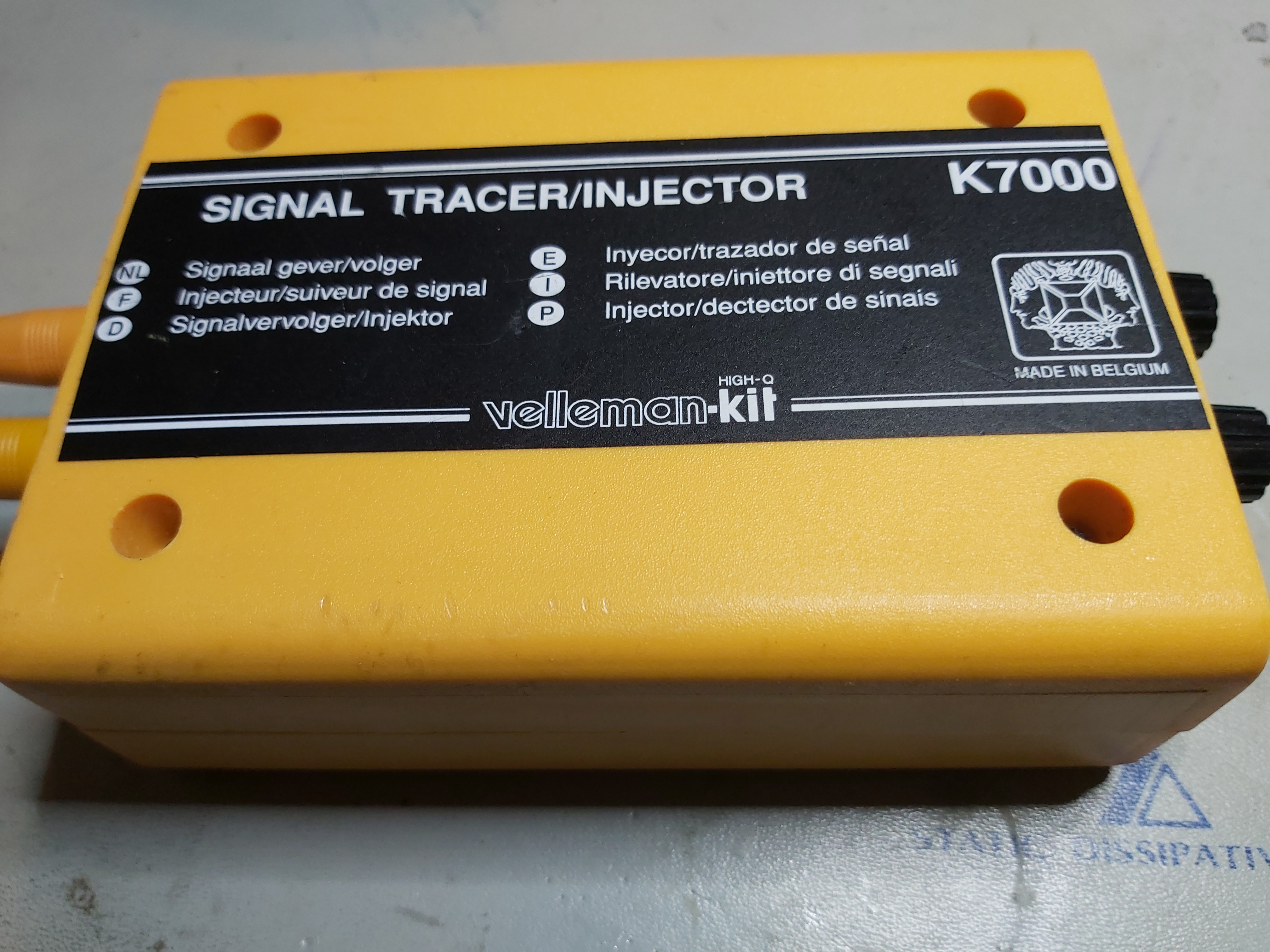
Years ago I bought Velleman K7000 signal tracer/injector kit and built it into this project box.
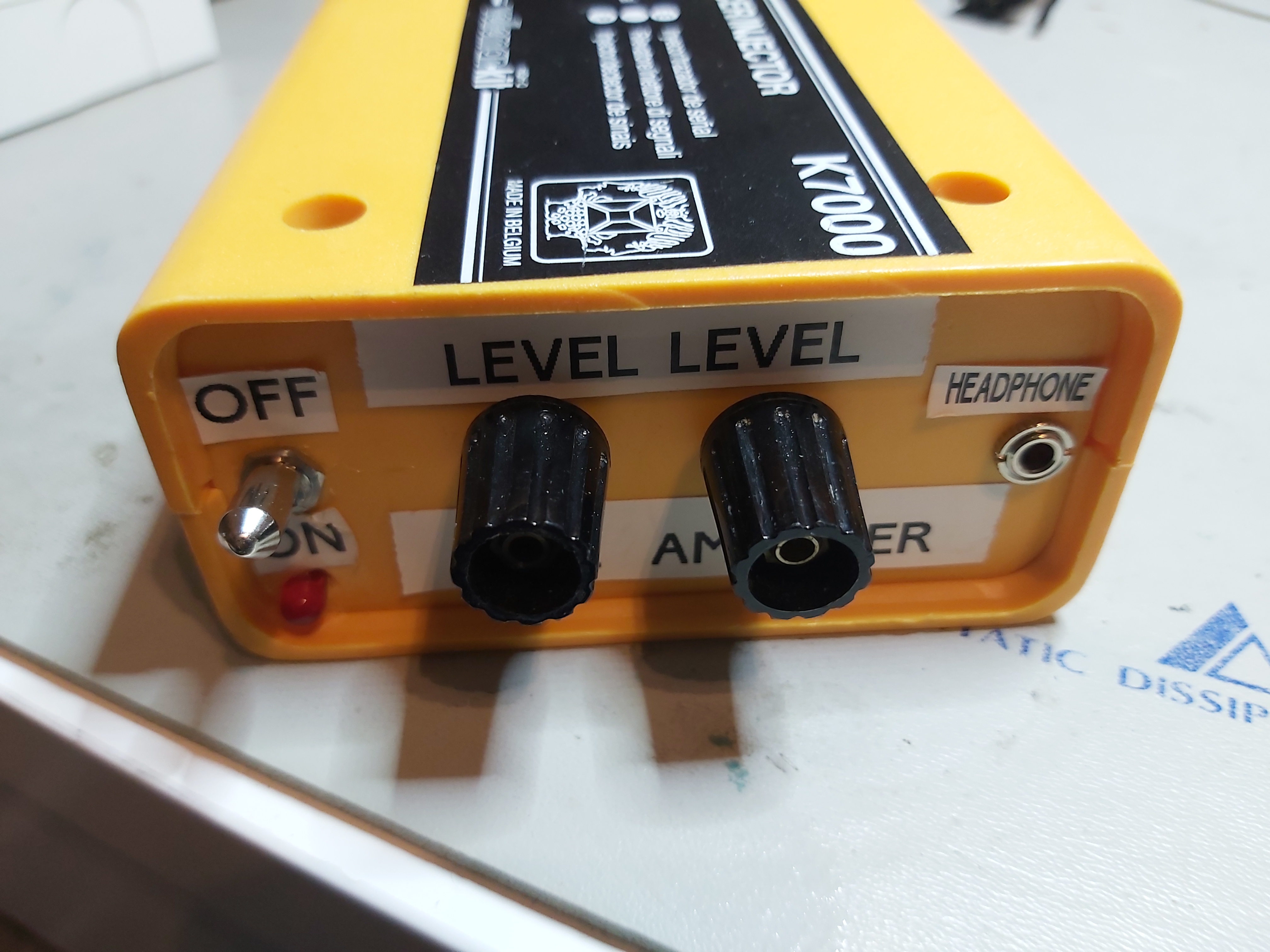
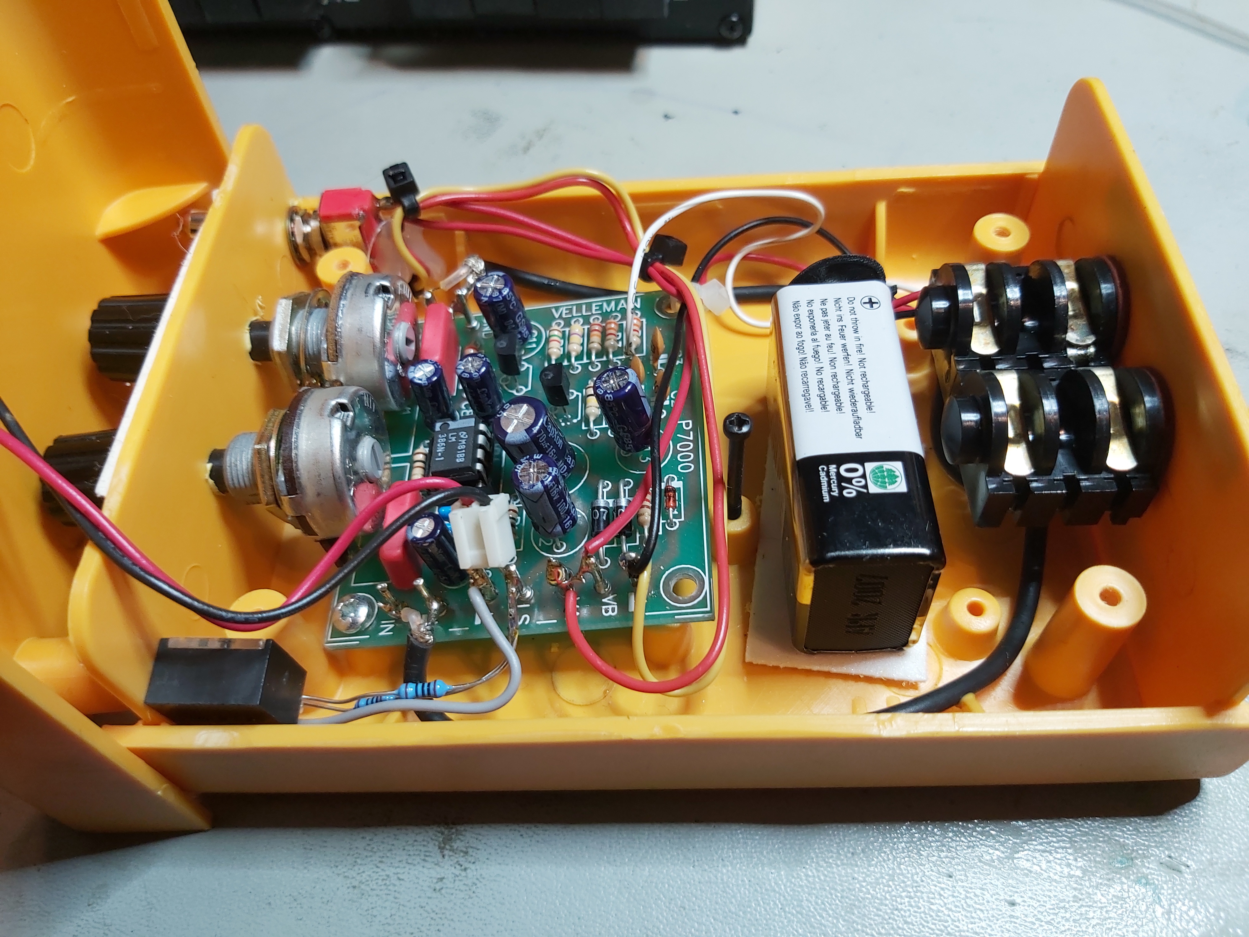
Here is view what is inside the box.
The Velleman Signal Tracer/Injector has been designed to detect or inject a specific signal into an audio circuit in need of repair so as to detect the fault. This it a kit that comes with the circuit board and components, the buyer needs to solder it together to make it work. After soldering the kit looks like this.

Here is technical data of the kit:
Signal injector:
0-2.5Vrms output (adjustable)
Output impedance: 1.5KΩ
Frequency: ± 1kHz
Signal tracer:
3.5mV to 10Vrms sensitivity (adjustable)
Gain: 40dB
Input impedance: 50KΩ
Output power: 0.5W/8Ω
PCB size 60 x 53mm
Power supply 7 to 9V AC or 9 to 12V DC, 150mA
Velleman K7000 signal tracer/injector kit is nowadays replaced with WSMI7000 SIGNAL TRACER/INJECTOR kit, that has very similar specifications (and seems to have same manual as K7000).
Official manufacturer documentation can be found at manufacturer official pages at https://www.velleman.eu/products/view/?country=ot&lang=en&id=9360. You can download the assembly instructions manual there or view it on-line at Doclayer.
Let’s take a look how this kit works. For analysis here is the circuit diagram from manual:
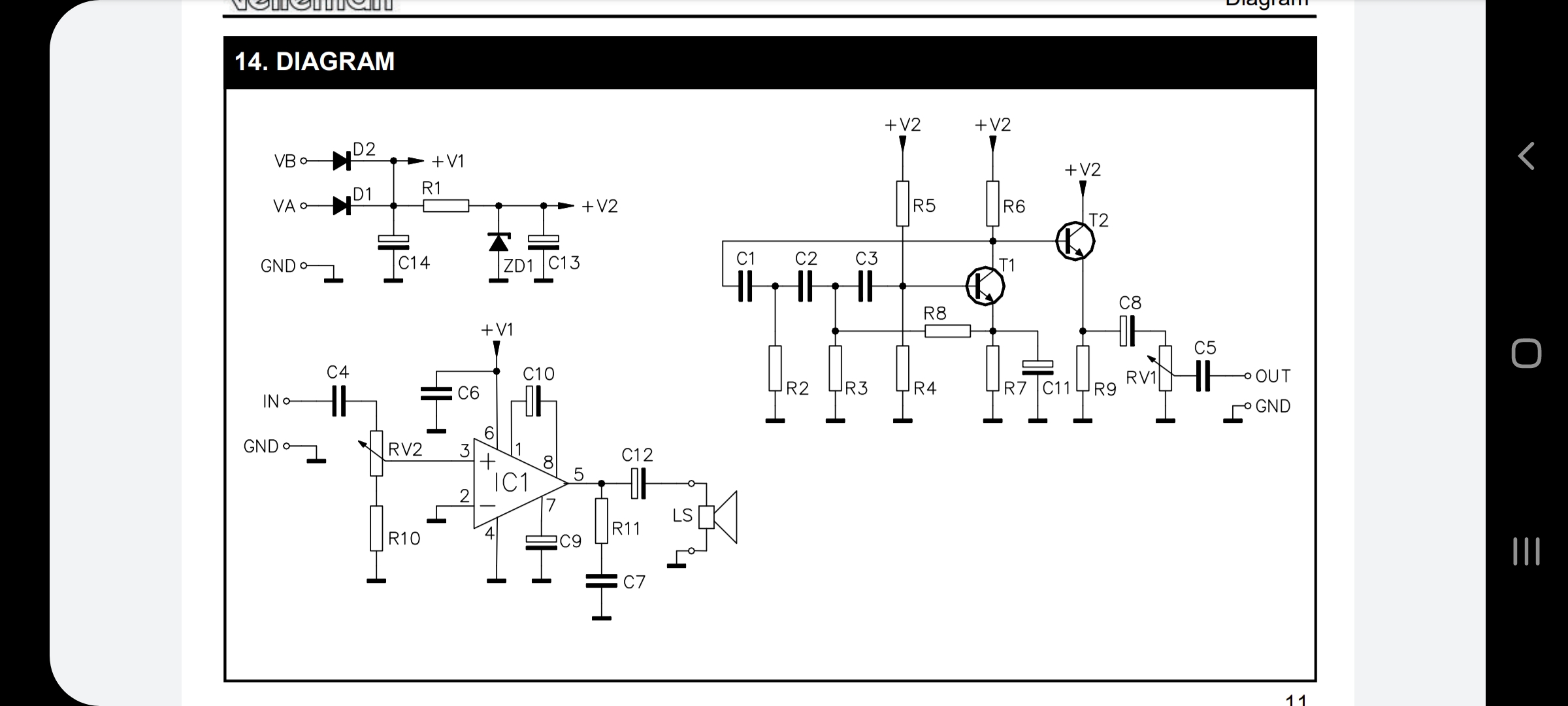
The transistor T1 works as a phase shift oscillator that produces around 1000 Hz sinewave signal. The transistor T2 works as buffer amplifier (emitter follower). The maximum output amplitude is around two volts RMS.
The IC1 (LM386) is a quite basic audio amplifier that can drive a small speaker. LM386 is an integrated circuit containing a low-voltage audio power amplifier that can output 0.25 to 1W power to a speaker with a circuit that has only a couple resistors and capacitors. In this circuit the amplifier gain is set to fixed 200. The amplitude of incoming signal is adjusted with a potentiometer. There is capacitor C4 that blocks DC but passes audio frequencies.
How does the kit work? The Velleman K7000 is a basic tool to troubleshoot radio and audio circuits, and works very well. Assembly is straightforward and simple, but you have to come up with a suitable enclosure/case. It is affordable, works well with audio circuits and is quite easy to solder together (if you have any experience in building electronics kits). If you can solder (need a good small iron) and follow directions, this works well (85 soldering points needs to be soldered). The components are on strips for you to place in the right order on the printed circuit board and the board is clearly marked. When building the K7000, if you follow the instructions carefully, it will work right away.
This kit is a very Good foundation for a signal tracer / injector project. The oscillator output is quite clean sine wave at around 1 kHz frequency (expect to get something between 900 Hz and 1.1 kHz).
The kit also comes with some limitations. The instructions are a bit minimal, though adequate. The circuit works quite well, but on my device the amplifier volume control potentiometer is somewhat more noisier than I would like when I adjust the volume. There is also some signal breakthrough from the oscillator part to the amplifier, that signal breakthrough is annoying sometimes.
This kit has use limited in tube circuits (max. contact voltage is 100v, but can be modified with three higher voltage capacitors to allow use on higher voltages). The original signal tracer also suffers from relatively low input impedance of of around 47 kohms.
Here are some YouTube videos that tell what this kit can do and how to built it:
Velleman K7000 Signal Tracer Kit
Signal Tracer – Velleman K7000
Using a Velleman K7000 Signal Tracer Kit as the skeleton and an electrical junction box as the body, you can have a fairly dependable signal tracer for under $40.
Modification / extending ideas:
This kit in original construction limited in tube circuits (max. contact voltage is 100v, but can be modified with three higher voltage capacitors to allow use on higher voltages). I have seen recommendation “I replaced the input and output capacitors with upgraded 600 volt versions – in case I wanted to use the tracer with tube amps.”
The original signal tracer suffers from relatively low input impedance of of around 47 kohms. With a simple FET probe the input impedance could be increased to over 2 Meg Ohm. When designing the amplifier circuit, keep in mind the Miller effect that is an issue with all inverting amplifiers whether the active component is a valve, FET, bipolar transistor or whatever.
The video K7000 Velleman Signal Tracer Active Probe shows how different types of volt meters can have a big effect on the circuit under test and the reliability of those measurements. The video has a look at the Velleman K7000 signal tracer and build at active FET probe that will really extend the capabilities of the signal tracer and make it work better. You can download K7000 Active Probe instructions.
Links to some instructions on using signal injector/tracer:
Velleman K7000 probe discussion
https://www.vintage-radio.net/forum/showthread.php?t=164273
PRINCIPLES OFSIGNAL TRACING
http://www.nostalgiaair.org/References/Articles/post/post01.htm
Automatic AF/RF Probe Circuit
https://www.vintage-radio.net/forum/attachment.php?attachmentid=223813&d=1609756084
There are lots of videos on YouTube which explain signal tracing:
https://www.youtube.com/watch?v=Vf7hopZ7TUs
https://www.youtube.com/watch?v=maIJC4J_jZw
https://www.youtube.com/watch?v=OGrkIC-Mov0
4 Comments
Tomi Engdahl says:
Transistor Radio Troubleshooting with Signal Tracer
https://www.youtube.com/watch?v=QZBH3cIZBTI
Carl Jackson says:
Thanks for the heads up on the Miller effect. Any recommendations how to minimize it? What low-impedence driver did you use?
Tomi Engdahl says:
Ja mikä parasta: tästä tuotteesta on todellista hyötyä kaikille vian etsijöille, jotka eivät omista oskilloskooppia.
Laite toimii seuraavasti: Syötetään testattavan laitteen sisäänmenoon audiosignaalia, yleisimmin siniaaltosignaalia audio generaattorista. Generaattorina on nykyään helpoin käyttää älypuhelinta (tai tietokonetta
https://uraltone.com/blog/audioprobe/
Audio proben ulostulo kytketään kitarakaapelilla kitaravahvistimeen (tai mihin tahansa muuhun vahvistimeen) ja proben maadoitushauenleuka kytketään mitattavan laitteen maahan (runko, jakin maa jne). Audio probella voidaan näin kuunnella miten signaali kulkee laitteessa. Yleensä aloitetaan sisäänmenosta, johon siis syötetään siniaaltoa puhelimesta. Kun tökkäät audio probella sisäänmeno jakin tip (kuuma, plus) liitäntää kuulet vahvistimesta puhelimesta tulevan siniaaltosignaalin. Voit sitten edetä signaalitietä pitkin kohti ulostuloa ja todeta missä kohdin signaali ei enää kulje. Näin on hyvin helppo paikantaa laitteen väärin kytketty tai vioittunut osio.
URALTONE ÄÄNI-ILMAISIN AKA AUDIO PROBE – RAKENNUSSARJA
https://uraltone.com/audioprobe.html
Tomi Engdahl says:
http://www.openmusiclabs.com/projects/audio-sniffer/