Telephone line over voltage protection: Here is my surge protector circuit design from 1995. It was available as a commercial product (with some small updates) for over 20 years. It did it’s job well, keeping the connected systems well protected.
While modern communications have largely shifted to fiber optics and digital packets, legacy copper pairs (POTS—Plain Old Telephone Service) and specialized analog telemetry loops remain widely deployed. Because these lines often run outdoors for hundreds of meters—or even kilometers—they act as giant antennas.
When a nearby lightning strike, power line induction, or electrostatic discharge (ESD) occurs, high-energy transients can travel directly down the copper pair. Without proper over-voltage protection, these surges will instantly destroy sensitive modem chipsets, telephone interfaces, or monitoring hardware.
Drawing from a robust design originally conceived in 1995 that has stood the test of time for nearly three decades, this post revisits the architectural philosophy of building a multi-stage surge protector capable of handling thousands of volts without sacrificing signal integrity.
The surge path on a POTS line is often underestimated, and a proper clamping stage plus a series resistor is what actually saves the modem front end.
The Engineering Challenge: High Energy vs. Fast Response
Designing an effective transient voltage suppressor for telecommunications requires balancing two contradictory demands:
1. Handling Massive Energy: Direct or indirect lightning strikes deliver thousands of amperes with high microsecond-to-millisecond energy profiles.
2. Preserving Signal Transparency: The circuit must not degrade normal telephony operations, which include low-frequency audio (300 Hz–3.4 kHz), high-voltage ringing signals (up to 90–110 V RMS AC), and high-impedance DC idle voltages (~48 V DC).
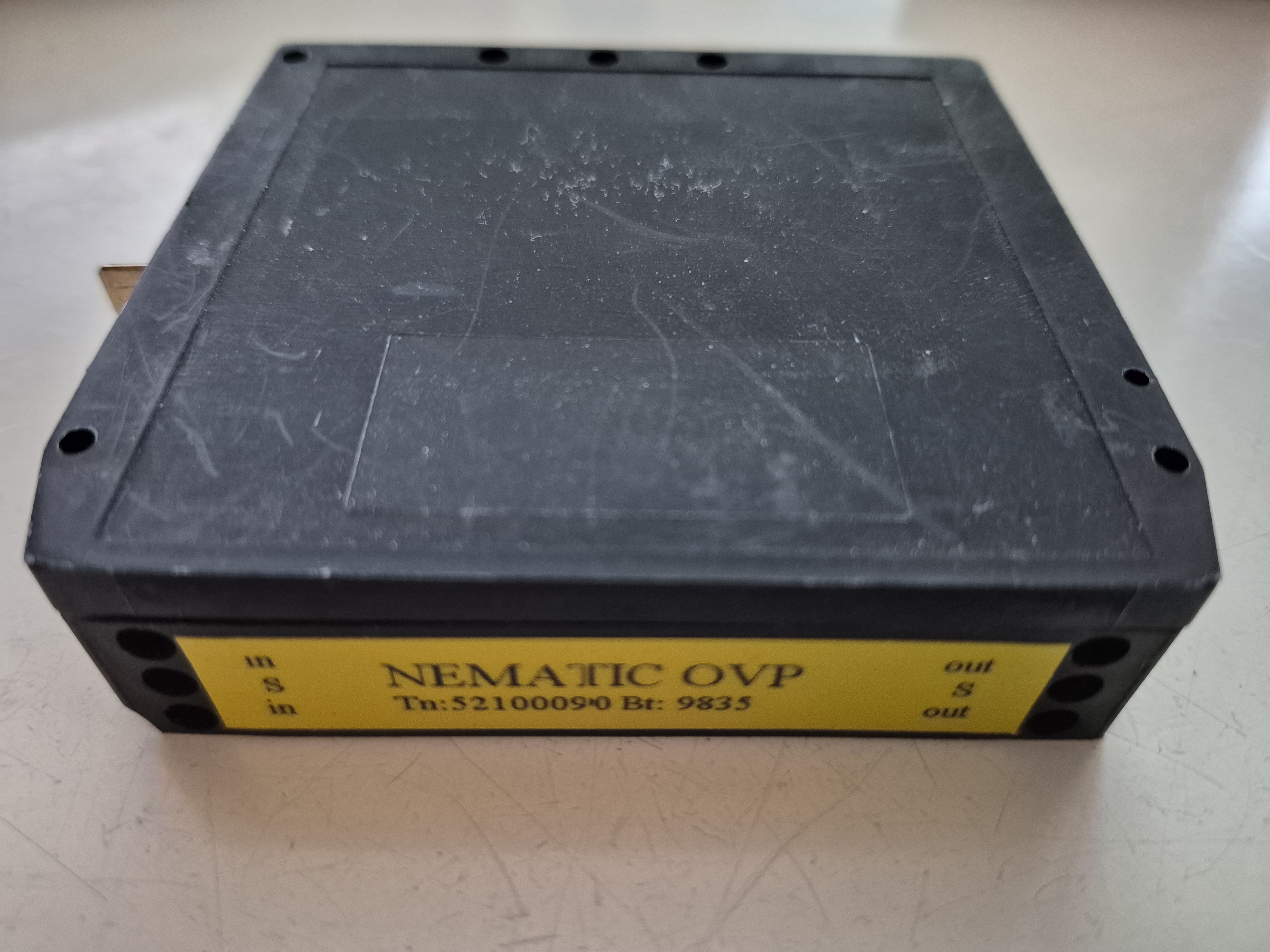
Here is the picture of the telephone line protector product. It is designed to be installed to a DIN rail within and automation cabinet. There are screw connections for line IN and OUT. In addition to there is a flat metal “abiko” contact for good ground connection. The IN side connects to the phone line connected to outdoor telephone network. The OUT side is connected to the modem.
Grounding is Everything: A surge protector is only as good as its earth connection. The ground lead from protector grounding connection must be kept as short and thick as possible, tied directly to a low-impedance earth ground.
Let’s see what is inside (old 1990′s version):
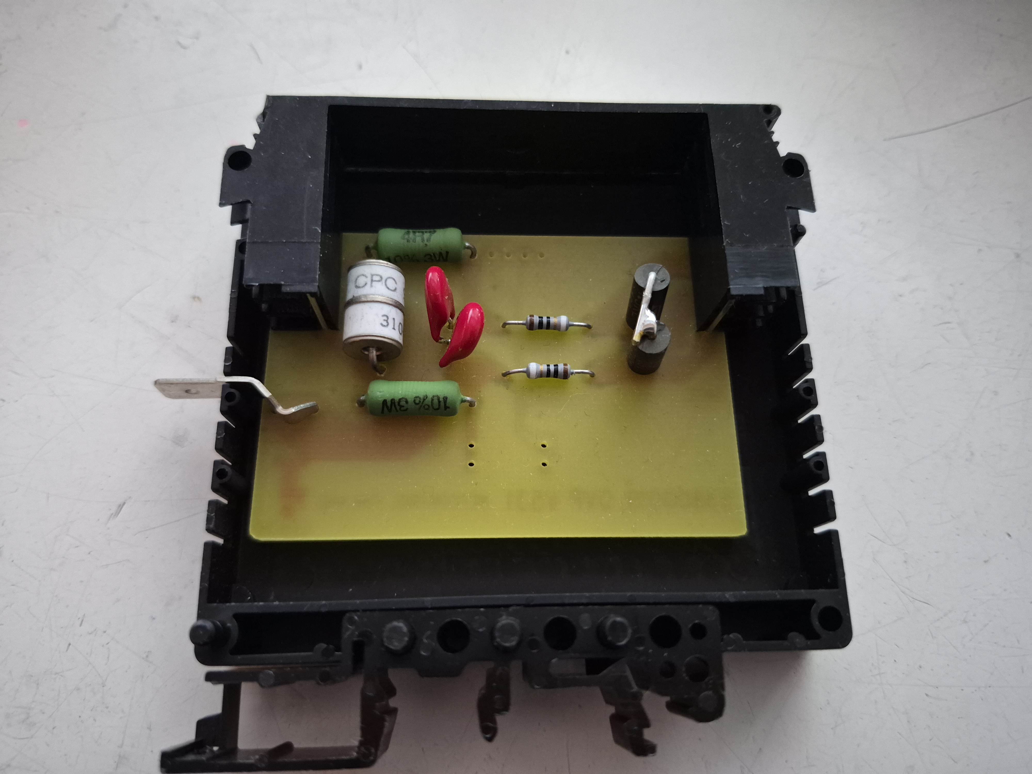
That white thing is a deal gas discharge tube over-voltage protector that dissipates most of the over-voltage surge. It is followed with two other layers of protection (VDR and surge protectors. There are multiple protection components because no single component can handle both extremes effectively. A component tough enough to absorb a lightning bolt is usually too slow or has too much parasitic capacitance, whereas a fast semiconductor clamp would instantly burn out from a heavy surge.
The solution is a coordinated, multi-stage protection cascade that divides and conquers the transient energy across progressive layers. This design works well with normal telephone lines and fixed modem-to-modem wired connections.
1. Stage 1: The Primary Heavy Lifter (Gas Discharge Tube)
The Component: A heavy-duty ceramic/glass Gas Discharge Tube (GDT)—represented by the white cylindrical element in the hardware layout.
Role: The first line of defense connected directly between the incoming tip/ring lines and earth ground.
How it works: Under normal conditions, the noble gas inside the tube acts as an insulator with extremely high resistance and low capacitance. When a high-voltage surge exceeds the DC breakdown voltage (typically 230V–350V+), the gas ionizes and creates a low-resistance plasma arc.
Advantage: GDTs can divert massive surge currents (often 5kA to 20kA+ per line) safely to ground.
Limitation: They have a relatively slow response time (taking a fraction of a microsecond to fire) and will “follow-on” with a short circuit if DC holding current is present, which is why subsequent stages are necessary.
2. Stage 2: The Medium Clamping Layer (VDR / MOV)
The Component: A Varistor (Voltage Dependent Resistor / MOV) placed downstream of the primary GDT.
Role: Bridges the gap between the coarse, high-voltage breakdown of the GDT and the sensitive semiconductor electronics downstream.
How it works: As the transient voltage rises, the MOV’s resistance drops non-linearly, clamping the peak voltage to a safer intermediate window before it reaches the final stage.
Coordination: A small series resistance or inductance is typically placed between Stage 1 and Stage 2. This delay/impedance ensures the slow-igniting GDT has enough time to fire and take the brunt of the high-energy pulse, preventing the MOV from taking the full direct strike energy.
3. Stage 3: The Precision Clamping Layer (Surgector / Transient Diodes)
The Component: A fast semiconductor clamping device (such as a thyristor surge protector/surgector or fast avalanche diode network).
Role: The final gatekeeper right before the protected electronics.
How it works: Semiconductors react in nanoseconds, clipping any remaining high-frequency spikes or voltage overshoot that escaped the GDT and VDR stages.
Final clamping level: Ensures that the voltage differential seen by the modem or transceiver IC never exceeds absolute maximum ratings (typically matching or slightly above the maximum ringing voltage envelope).
A coarse GDT handles the massive bulk energy of a slow surge, while a coordinated series resistor and downstream fast semiconductor clamp (like a low-capacitance TVS diode array) catch the fast-rising initial transient that the GDT missed.
Fusing & Fail-Safe Design: In catastrophic failure modes (e.g., continuous power-cross where high-voltage AC mains accidentally short onto the telephone line), components like MOVs can overheat and short. The resistors used in this design are resistors that will safely fail in case if serious overload. This fail-safe mechanisms ensures the device fails open safely without causing a fire hazard. The gas discharge tube voltage rating is selected according to telephone line protection requirements (will not conduct in expected failure cases for phone line when it should not, like grounding failure or mains voltage touches line).
Limitations of this design: Because telephone lines cab carry voice and data (such as ADSL or FSK caller ID), excessive parallel capacitance from protection components will attenuate high-frequency signals. This design was originally designed for normal analogue telephone frequencies in mind, and as higher capacitance than what is preferred with ADSL frequencies (not tested but analyzed that would attenuate ADSL signals considerably).
When protecting high-speed data lines (such as VDSL2, ISDN, Ethernet, or industrial serial buses), choosing between Gas Discharge Tubes (GDTs) and Metal Oxide Varistors (MOVs / VDRs) involves a strict engineering trade-off between energy handling capability, response speed, and parasitic capacitance. GDTs Win Here: GDTs consist of two or three metallic electrodes separated by a noble gas inside a small ceramic or glass capsule. Because the dielectric medium is primarily gas, the parallel capacitance is negligible (often under 1 pF). This makes GDTs virtually invisible to high-frequency signals, preserving eye patterns and preventing signal attenuation on fast differential data lines. MOVs are generally unsuitable for direct placement across high-speed data lines. Instead, engineers typically use a coordinated two-stage hybrid architecture combining a heavy-duty Gas Discharge Tube (GDT) for coarse energy dissipation and a ultra-low-capacitance Transient Voltage Suppression (TVS) diode array for precision clamping. My original design would have needed some component values changes to work well with ADSL signals – that would have been probably been some simple design changes, but the testing and re-certifying the modified version would have have taken too much effort (time and money) to be feasible.
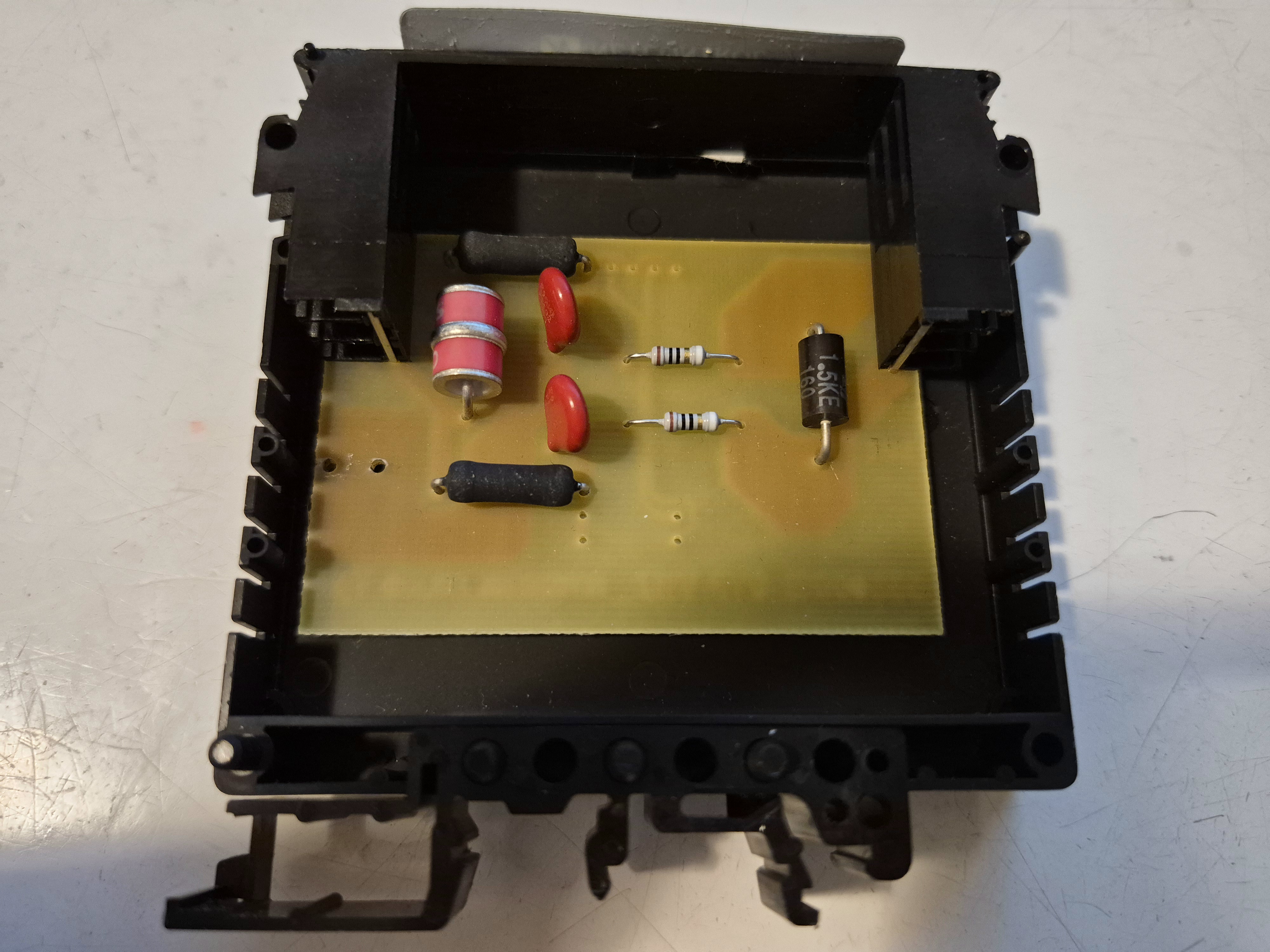
Over the time some of the components needed to be be changed due component availability. Here is a picture if one later version:
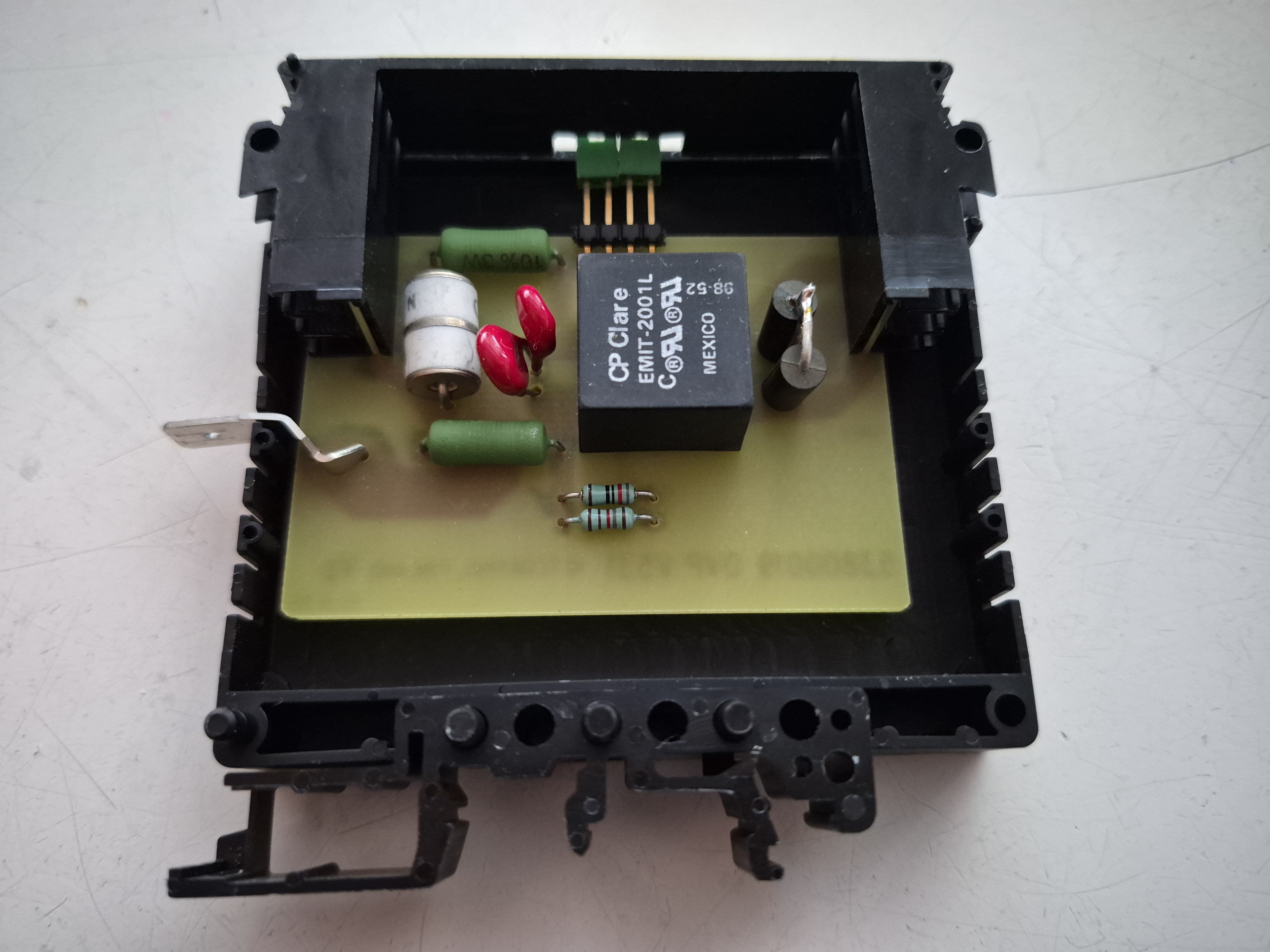
There is was another version that has transformer isolation. This is designed to work with fixed line modem-modem connections. The transformer provides isolation between incoming line (several kV). This arrangement can provide protections against ground potential rise situations. This second transformer isolated version is built to the same circuit board as the first version shown above.
Links to related material:
https://www.epanorama.net/blog/2025/03/03/phone-line-over-voltage-protection/
https://www.epanorama.net/documents/surge/telesurge.html
https://www.epanorama.net/documents/surge/surgesuppres.html