Arduino AC measurements

Sometimes there is need to measure power going to different devices. Measuring DC power consumption is pretty easy, but when you try to do the same for AC circuit, things start to become complicated. How to Measure Electrical Power article will discuss best practices for making electrical power measurements, starting with power measurement basics and proceeding to the types of instruments and associated components typically used to make measurements. DC power measurement is relatively simple as the equation is simply watts = volts x amps. For AC power measurement, the power factor (PF) introduces complexity as watts = volts x amps x PF. This measurement of AC power is referred to as active power, true power or real power. Power is typically measured with a digital power analyzer or a DSO (digital storage oscilloscope) with power-analysis firmware.

What if you want to implement power mesurement yourself? Power consumption in AC circuit is correctly measured by calculating volts x amps = volt-amps (apparent power) over time, using at least one complete cycle. Using digitizing techniques, the instantaneous voltage is multiplied by the instantaneous current then accumulated and integrated over a specific time period to provide a measurement. This method provides a true power measurement and true RMS measurements for any waveform up to the bandwidth of the instrument.

In addition to math, you will need to provide some sensors to measure current and voltage. For AC current measurements potential sensor types are shunt resistor, current transformer, hall current sensor and rogowski coil. Usually current transformer and hall current sensor are the most suitable types to use with Arduino (they both provide isolation from measurent circuit). For AC voltage measurements the most suitable sensor types are voltage transformercapacitive voltage divider and resistive voltage divider. From those alternatives only voltage transformer can provide galvanic isolation from circit being measured.

Can this measurement of AC power made using Arduino? The answer is yes, ans there are several ways it can be done. AC Power Theory – Arduino maths web page provides inntroduction how this can be implemented with Arduino (check also Advanced maths). There is EmonLib library that provides you a set of ready made AC measurement calculation routines that you can use easily.

Arduino sketch – voltage and current from OpenEnergyMonitor project shows how you can do the AC power measurements with Arduino.

#include "EmonLib.h"              // Include Emon Library
EnergyMonitor emon1;              // Create an instance

void setup()
{  
  Serial.begin(9600);
  
  emon1.voltage(2, 234.26, 1.7);  // Voltage: input pin, calibration, phase_shift
  emon1.current(1, 111.1);        // Current: input pin, calibration.
}

void loop()
{
  emon1.calcVI(20,2000);          // Calculate all. No.of crossings, time-out
  emon1.serialprint();            // Print out all variables
}

To us this simple looking source code, you need to have EmonLib installed (it does all the complex calculations so you don’t need to worry about them). The simplest way is to download EmonLib zip packet and extract it to arduino libraries folder. It will give the needed library and project examples.

Here is example code I used “voltage_and_current” (my modified version):

// EmonLibrary examples openenergymonitor.org, Licence GNU GPL V3

#include “EmonLib.h” // Include Emon Library
EnergyMonitor emon1; // Create an instance

void setup()
{
Serial.begin(9600);

emon1.voltage(2, 11.7 /* 234.26 */, 1 /* 1.7 */); // Voltage: input pin, calibration, phase_shift
emon1.current(1, 5.5 /* 111.1 */); // Current: input pin, calibration.
}

void loop()
{
emon1.calcVI(20,2000); // Calculate all. No.of half wavelengths (crossings), time-out
emon1.serialprint(); // Print out all variables (realpower, apparent power, Vrms, Irms, power factor)

float realPower = emon1.realPower; //extract Real Power into variable
float apparentPower = emon1.apparentPower; //extract Apparent Power into variable
float powerFActor = emon1.powerFactor; //extract Power Factor into Variable
float supplyVoltage = emon1.Vrms; //extract Vrms into Variable
float Irms = emon1.Irms; //extract Irms into Variable
}

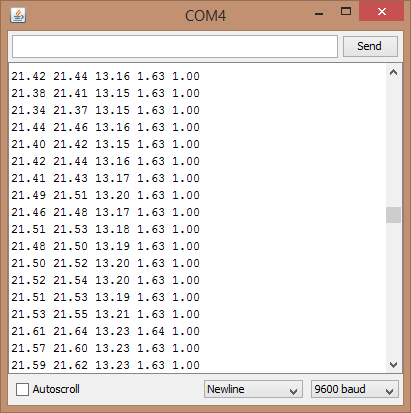
I got the following output when I measured 20W halogen lamp system:

ardpower


Here is picture of the Arduino Nano + Nano Sensor Shield based test circuit I used:

image

In this test circuit I measured 12V halogen lamp system current and voltage. For current mesurement I used ACS712 sensor based current measurement sensor module with +-5A current measurement range. For voltage measurement I used a simple voltage divider module (22k ohm from input pin to +5V, 22 kohms from input pin to ground, 120 kohms from AC voltage source to input pin).

One note in plannng to use this power measurements: If you plan to measure mains power, you need to understand all the safety details related to mains power. When testing the circuit, I highly recommend that you have a low voltage test system that you can sefely test and debug your designs (hardware and software). I have used 12V halogen lamp system for this: a traditional 12V transformer gives out safe 12V AC output usually at several amperes, you can control the load easily by turning 12V lamps on/off as needed. When you have debugged your design at safe voltages, you can start thinking of working with higher dangerlous voltages!


Related project pages:

OpenEnergyMonitor building blocks

Emoncms

Home Energy Monitoring System

Watt Meter build walks you through Power Measurement basics

DIY Digital AC Watt Meter

Digital Data from a Cheap Power Meter


115 Comments

  1. Tomi Engdahl says:

    Safely Measuring Single And Three-Phase Power
    https://hackaday.com/2019/07/06/safely-measuring-single-and-three-phase-power/

    There are many reasons why one would want to measure voltage and current in a project, some applications requiring one to measure mains and even three-phase voltage to analyze the characteristics of a device under test, or in a production environment. This led [Michael Klopfer] at the University of California, Irvine along with a group of students to develop a fully isolated board to analyze both single and three-phase mains systems.

    Each of these boards consists out of two sections: one is the high-voltage side, with the single phase board using the Analog Devices ADE7953 and the three-phase board the ADE9708.

    https://github.com/CalPlug/ADE7953-Wattmeter/

    Reply
  2. Tomi Engdahl says:

    How to build an Arduino energy monitor – measuring mains voltage and current
    https://learn.openenergymonitor.org/electricity-monitoring/ctac/how-to-build-an-arduino-energy-monitor

    This guide details how to build a simple electricity energy monitor on that can be used to measure how much electrical energy you use in your home. It measures voltage with an AC to AC power adapter and current with a clip on CT sensor, making the setup quite safe as no high voltage work is needed.

    Reply
  3. Tomi Engdahl says:

    Logging 2 Electricity Smart Meters Using Arduino Nano Every © GPL3+
    https://create.arduino.cc/projecthub/Torschtele/logging-2-electricity-smart-meters-using-arduino-nano-every-99f934

    Data logging from two electricity meters (type “eHZ”) simultaneously and store data (time and value of reading) to an SD card.

    Reply
  4. Tomi Engdahl says:

    This energy monitor plug is actually really smart inside.
    https://www.youtube.com/watch?v=fRGKilvExMo

    There is a very fancy chip inside that rivals the accuracy of the Hopi, but with the slight annoyance of only displaying one or two variables at a time.

    Reply
  5. Tomi Engdahl says:

    Home Power Monitoring
    With PZEM-016, monitoring of 3 phases in main electrical arrival of my house
    https://hackaday.io/project/169037-home-power-monitoring

    Reply
  6. Tomi Engdahl says:

    This Digi-Key Electronics article introduces the idea of using a current sense transformer and a Nano 33 IoT to obtain the data required to simply and cost-effectively implement a predictive maintenance tinyML application: https://bit.ly/2Sn2Roq

    Reply
  7. Tomi Engdahl says:

    The digital home electrical meters typically measure nowadays the current and voltage going on the live wire. The current can be measured with a very low value shunt resistor in series with the line or using magnetic sensor (currrent transformer, rogowski coil or hall sensor). Voltage is typically measured with a resistive or capacitive voltage divider or using voltage transformer.

    Reply
  8. Tomi Engdahl says:

    Can my $15 DIY AC/DC Current Clamp keep up with a commercial one? || DIY or Buy
    https://www.youtube.com/watch?v=ohQF79cMODw

    In this episode of DIY or Buy we will be having a closer look at my broken AC/DC current clamp which can be also called a current probe. The job of such a current clamp is simple, visualizing the current waveform on an oscilloscope. So in this video I will explain how such a current clamp functions and how we can make a DIY alternative in order to find out whether it makes sense to DIY such a tool or whether we should stick to the commercial solution instead. Let’s get started!

    Reply
  9. Tomi Engdahl says:

    Custom Isolated Variac Is Truly One Of A Kind
    https://hackaday.com/2021/08/17/custom-isolated-variac-is-truly-one-of-a-kind/

    It’s no surprise that many hardware hackers avoid working with AC, and frankly, we can’t blame them. The potential consequences of making a mistake when working with mains voltages are far greater than anything that can happen when you’re fiddling with a 3.3 V circuit. But if you do ever find yourself leaning towards the sparky side, you’d be wise to outfit your bench with the appropriate equipment.

    Take for example this absolutely gorgeous variable isolation transformer built by [Lajt]. It might look like a high-end piece of professional test equipment, but as the extensive write-up and build photographs can attest, this is a completely custom job. The downside is that this particular machine will probably never be duplicated, especially given the fact its isolation transformer was built on commission by a local company, but at least we can look at it and dream.

    https://lajtronix.eu/2021/04/29/diy-variable-isolation-transformer/

    Reply
  10. Tomi Engdahl says:

    Using Homebrew Coils To Measure Mains Current, And Taking The Circuit Breaker Challenge
    https://hackaday.com/2021/09/12/using-homebrew-coils-measure-mains-current-and-taking-the-circuit-breaker-challenge/

    Like many hackers, [Matthias Wandel] has a penchant for measuring the world around him, and quantifying the goings-on in his home is a bit of a hobby. And so when it came time to sense the current flowing in the wires of his house, he did what any of us would do: he built his own current sensing system.

    Inductive current measuring using Raspberry Pi
    https://www.youtube.com/watch?v=P47pjVyPP3w

    Reply
  11. Tomi Engdahl says:

    Homemade DC/AC Oscilloscope Current Clamp | Hall Sensor + Ferrite Core
    https://www.youtube.com/watch?v=SH0AMdRiYTE

    The clamp works perfect but is not the most professional tool ever, it is more as an example in order to understand the theory. You could always improve it using better OP AMP and a better circuit. It could observe both DC and AC currents with a range up to 9A. I hole you like it.

    I was looking for a current probe like this not long ago but gave up due to the high prices. This one is quite possibly the ugliest looking probe I’ve ever seen, but that’s OK because it obviously works! Why should I buy a probe costing hundreds of dollars when I can now easily build my own for dirt cheap? I learned something today. Great job, and I look forward to seeing more from you!

    What a wonderful, creative, low cost hack! This is exactly the basis I needed for a non-invasive high current monitor for a battery back up sump pump. Thanks so much for sharing!

    How a AC/DC Clamp-Meter works
    https://www.youtube.com/watch?v=v1ZaUt5P8qo

    How can a clamp-meter measure AC- and DC-current without interrupting the circuit?

    Reply
  12. Tomi Engdahl says:

    DIY current sensor (hall effect)
    https://www.youtube.com/watch?v=FK7WJArizP4

    DIY cheap and simple scalable current sensor. I forgot to mention it’s isolated from the circuit where is measuring current. Works on ac and dc. Can be made for under 2 $ but the normal market price are about 25$, you can find them on google typing “current half effect sensor”

    Reply
  13. Tomi Engdahl says:

    DIY ESP32 AC Power Meter (with Home Assistant/Automation Integration)
    https://www.youtube.com/watch?v=PSzkaSy5lHY

    In this project I will show you how to build an ESP32 AC power meter that can be used with your home assistant setup. That means I will firstly explain how to actually measure and calculate real and apparent power along with the power factor and then I will show you how to use the ESP32 in combination with some complementary components in order to create the power meter. Let’s get started!

    Reply
  14. Tomi Engdahl says:

    Hack Your Home Part 3: Power Monitor
    https://www.youtube.com/watch?v=uZyJWVA_gyE

    In addition to controlling appliances, we can also measure how much power they are using. In this episode, you will use a CT sensor to measure the current being drawn by an appliance and post that data to the Internet. Note that a little bit of math is necessary to figure out the average current.

    Reply
  15. Tomi Engdahl says:

    DIY Arduino power/energy meter
    https://www.youtube.com/watch?v=_PKQdEUam6Y

    Months back we have build a current meter. Now, the last emter tutorial, we calculate power and print it on an OLED display. This project will measure current, voltage, power and energy. I’ve used a shunt resistor for the curent measure. More info below.

    Reply
  16. Tomi Engdahl says:

    #347 Measuring Mains Voltage, Current, and Power for Home Automation
    https://www.youtube.com/watch?v=Vb9-pbLdsfQ

    In video #321, we looked at DC current sensors. Today we will look at how to measure AC mains currents, which is much more difficult. And more dangerous because it can kill you if you do not pay attention. And, because measuring AC power is useful in home automation, we will also look at how to measure voltage and calculate power. To measure correctly, we have to learn about phase shifts and power factor. And I will tell you the essential rule to live long around high voltages.

    Reply
  17. Tomi Engdahl says:

    Accurately Track Your Mains Frequency
    https://hackaday.com/2022/02/15/accurately-track-your-mains-frequency/

    Depending upon where in the world you live, AC mains frequency is either 50Hz or 60Hz, and that frequency is maintained accurately enough over time that it can be used as a time reference for a clock. Oddly it’s rarely exactly that figure though, instead it varies slightly with load on the network and the operators will adjust it to keep a constant frequency over a longer period. These small variations in frequency can easily be measured, and [jp3141] has created a circuit that does exactly that.

    https://github.com/jp3141/60Hz

    Reply
  18. Tomi Engdahl says:

    Smart Energy Monitoring System Using ESP32
    https://youtu.be/DKNkas1loBw

    Reply
  19. Tomi Engdahl says:

    IoT Based Energy Consumption Cost Calculator Using ESP8266

    Circuit & Code: https://circuitdiagrams.in/iot-based-energy-consumption-cost-calculator/

    Reply
  20. Tomi Engdahl says:

    What’s In A Wattmeter?
    https://hackaday.com/2022/05/13/whats-in-a-wattmeter/

    The idea behind watts seems deceptively simple. By definition, a watt is the amount of work done when one ampere of current flows between a potential of one volt. If you think about it, a watt is basically how much work is done by a 1V source across a 1Ω resistor. That’s easy to say, but how do you measure it in the real world? [DiodeGoneWild] has the answer in a recent video where he tears a few wattmeters open.

    There are plenty of practical concerns. With AC, for example, the phase of the components matters. The first 11 minutes of the video are somewhat of a theory review, but then the cat intervenes and we get to see some actual hardware.

    Wattmeters – what’s inside, how do they work
    https://www.youtube.com/watch?v=SVP3on0oHHs

    Reply
  21. Tomi Engdahl says:

    EdenOff is a Nano 33 BLE Sense-based device that can be placed inside of a wall outlet to predict power outages using a tinyML model.

    This Arduino device can anticipate power outages with tinyML
    https://blog.arduino.cc/2022/05/24/this-arduino-device-can-anticipate-power-outages-with-tinyml/

    Bandini then deployed this model to a DIY setup by first connecting a Nano 33 BLE Sense with its onboard temperature sensor to an external ZMPT101B voltage sensor. Users can view the device in operation with its seven-segment display and hear the buzzer if a failure is detected. Lastly, the entire package is portable thanks to its LiPo battery and micro-USB charging circuitry.

    https://studio.edgeimpulse.com/public/90995/latest

    Reply
  22. Tomi Engdahl says:

    Arduino Based Overvoltage And Undervoltage Protection System
    Full Details & Project: https://circuitdiagrams.in/overvoltage-and-undervoltage-protection-system/

    Reply
  23. Tomi Engdahl says:

    https://www.facebook.com/438304376511718/posts/pfbid0mbdM3pfVrY22KqrT3zvBbWS9FZFfV7XU2ZPfmbTB2wfDbB74W1hPnp6FuSsRJoBSl/

    I have completed this project assembly and am glad about the turn out of the whole working process.

    This is an electrical load management system, which monitors the maximum load an output source can provide.
    The preset load ratings can be easily key into the microcontroller internal Eeprom memory using the 4×4 keypad module.

    Once the load ratings of each line gets reached, the system will automatically cuts out the particular line until the load ratings are reset.

    I couldn’t have completed this project to this working level, if not for the inputs that I got from Martins Obi who guilded me how to rectify the challenges I had while programming this project.

    I have shared the design information for this project on the video description for the project demonstration, as you can find both the schematic diagram, Arduino code and further materials that I made available, inclusive with the corrected code from Martins, here
    https://youtu.be/DQDOIFxhuCM

    #project #design #programming #embeddedsystems #Electronicsdesign #iotdevices #arduinoproject

    Reply
  24. Tomi Engdahl says:

    High Precision Digital AC Energy Meter Circuit [Voltage, Current, Power, KWh]
    https://m.youtube.com/watch?v=1I6Bz7_DOGs

    ======================================
    Disclaimer: Some parts of this circuit carry 220V Mains voltage. Be careful with your experiments. If you are a beginner, ask some experienced users to guide you.
    ======================================
    Dealing with the 220V-AC mains voltage and measuring the AC loads’ true power, voltage, and current parameters are always considered a big challenge for electronic designers, both in circuit design and calculations. The situation gets more complex when we deal with the inductive loads because inductive loads alter the sine-wave shape of the AC signal (resistive loads don’t).
    In this article/video, I introduced a circuit that can measure the AC voltage, RMS current, active power, apparent power, power factor, and energy consumption (KWh) of the loads. I used an Arduino-Nano board as a processor to make this more educational-friendly and attractive even for beginners. The device independently measures the aforementioned parameters and displays the results on a 4*20 LCD. The measurement error rate is around 0.5% or even lower.

    Reply
  25. Tomi Engdahl says:

    Over and Under Voltage Protection using Arduino
    Full video and project file can be found in this link:
    https://youtu.be/twTiG3czHi8

    Reply
  26. Tomi Engdahl says:

    A DIY high-precision digital AC meter capable of handling inductive loads.

    This high-precision AC meter handles inductive loads
    https://blog.arduino.cc/2022/08/05/this-high-precision-ac-meter-handles-inductive-loads/

    This DIY AC meter can take the power factor into account, which lets it calculate an accurate reading of the real power of a circuit. An Arduino Nano board monitors a HLW8032 energy metering IC that measures line voltage and current. The HLW8032 calculates active power, apparent power, and the power factor and sends that data to the Arduino via UART. The Arduino then displays that data on a 4×20 character LCD screen. All of the components mount onto a custom PCB that contains input terminals for the AC source and output terminals for the load.

    Reply
  27. Tomi Engdahl says:

    In-Package Hall-Effect Current Sensing: Tackling the Drift Challenge
    Jan. 20, 2022
    Current sensing is on a trajectory to intersect with the global high-voltage trend of robust, high-performing systems. Discover the tradeoffs between isolated shunt-based, closed-loop Hall-effect, and in-package Hall-effect current sensors.
    https://www.electronicdesign.com/technologies/analog/article/21163858/texas-instruments-inpackage-halleffect-current-sensing-tackling-the-drift-challenge?utm_source=EG+ED++Sponsor+Paid+Promos&utm_medium=email&utm_campaign=CPS220914097&o_eid=7211D2691390C9R&rdx.identpull=omeda|7211D2691390C9R&oly_enc_id=7211D2691390C9R

    From autonomous vehicles to aircraft to factory floors, electrification and automation advances are rapidly transforming our world. Systems that were previously mechanical or hybrid are moving toward full automation and electrification thanks to increases in performance and reliability, along with the lower total lifetime costs of fully automated solutions.

    In fact, we’re in the middle of a fourth industrial revolution focused on automation and smarter monitoring, also known as Industry 4.0. With the electrification revolution in full swing, high-voltage systems are enabling higher efficiency and performance.

    For those systems incorporating high-voltage domains, signal and power isolation can help protect people and critical circuits from high-voltage ac or dc power sources and loads. Adding more electrical functionality makes it increasingly important to shrink these systems to make them easier to scale while also reducing bill of materials, simplifying design, and maintaining high performance.

    Reply
  28. Tomi Engdahl says:

    How to measure AC Current Using Arduino & CT Senosr
    Project & Code: https://circuitdiagrams.in/ac-current-measurement-using-arduino/

    Reply
  29. Tomi Engdahl says:

    DIY Smart Distribution Board with Wi-Fi | IoT Arduino Project
    https://www.youtube.com/watch?v=YGajnfcQebY

    How to make a smart distribution board with Wi-Fi and display.
    It can measure voltage, power, current, frequency, power factor, energy, and temperature and sends data to the internet.
    It uses ESP8266 and can be programmed just like an Arduino.
    Power measurements are done by PZEM-004T-100A v3.0

    This is Smart Distribution Board based on ESP8266
    https://github.com/electrical-pro/SmartBoard/

    Reply
  30. Tomi Engdahl says:

    Home Automation Project WiFi Breaker DIY Smart Home Tech Relay 1 Hour!
    https://www.youtube.com/watch?v=nV82j-AleMk

    Power Distribution Box can control all kinds of electrical equipment and connect sensors to realize the function of security system. Home Automation Project DIY Smart Home Tech 8 Channel Smart Relay Box (WiFi Circuit Breaker) details for 1 hours take the video.

    Reply
  31. Tomi Engdahl says:

    Monitor your energy consumption through the Arduino IoT Cloud using a MKR WiFi 1010, a MKR 485 Shield, and a Modbus-compatible energy meter.

    Arduino IoT Based Energy Meter
    https://create.arduino.cc/projecthub/Arduino_Genuino/arduino-iot-based-energy-meter-1b2009

    Monitor your energy consumption through the Arduino IoT Cloud using a MKR WiFi 1010, a MKR 485 Shield and a Modbus compatible energy meter.

    This tutorial provides a step-by-step explanation of how to set up your new energy meter, using the widely used Modbus protocol to monitor your data. If you are new to the topic, we recommend you read our article on Modbus before getting started.

    Reply
  32. Tomi Engdahl says:

    Monitor your electricity consumption through the Arduino IoT Cloud using a MKR WiFi 1010, a MKR 485 Shield, and a Modbus-compatible energy meter: https://projecthub.arduino.cc/Arduino_Genuino/e914c8ed-7628-404c-9725-54a82309393d

    Reply
  33. Tomi Engdahl says:

    TL431 rogowski coil
    https://hackaday.io/project/190985-tl431-rogowski-coil

    Rogowski coil current sensor using cheap shunt regulators as opamps.
    StephenStephen

    A rogowski coil based current sensor involving some significant abuse of TL431 shunt regulators

    Details

    Rogowski coils are a popular type of current sensor used for power electronics development. Wikipedia has a good introduction to them: https://en.m.wikipedia.org/wiki/Rogowski_coil . If you fancy getting a good one then PEM https://www.pemuk.com/ will happily take £1000 off you and give you a calibrated, 50MHz, lots of amps coil. Some of the big players (eg Keysight) will rebrand the PEM ones so they’re clearly good bits of kit.

    I, however, cannot justify getting one of those. I do get to play with them at work but that’s not useful in my home lab.

    The coil responds to the rate of change of current (di/dt). In order to get the current, we need to integrate this. Usually, we would use an opamp as an integrator. it just takes a couple of resistors and a capacitor. We need to be careful of the DC offsets (voltage and current), bandwidth and design the coil carefully. As analogue integrators are not perfect we can have to have a minimum frequency otherwise the integrator will windup and crash into the rails.

    I’ve made a couple of coils before with fast, low offset opamps so this project felt like it needed something a bit different.

    For this project I decided to abuse some TL431 shunt regulators. TL431 regulators have a pretty good bandwidth, a fixed reference on the positive terminal and most importantly are cheap and readily available. I have a bag of them of dubious origin…

    Reply
  34. Tomi Engdahl says:

    What is a pulse output energy meter and how can you use it to analyze your bill?
    https://thingslog.com/blog/2021/08/11/what-is-pulse-output-energy-meter/

    Any energy meter has a pulse output option. The pulse output could be optical – a blinking diode (flashing led) used for calibrating the unit or electrical (so-called S0) pulse output.
    Blinking leds

    Any energy meter has, the flashing led. Next to the led typically, you will see how many blinks are equal to a certain amount of energy.

    Reply
  35. Tomi Engdahl says:

    One of the joys of writing for Hackaday comes in learning new things which even after a long engineering background haven’t yet come your way. So it is with the Rogowski coil, an AC current sensing coil which is unlike conventional current transformers in that it’s open ended — in other words not needing to be closed around the conductor it’s measuring….

    https://hackaday.com/2023/07/16/a-current-sensing-coil-thats-open-ended/?fbclid=IwAR2vxxowfPAz-FCH-mLxk4AakZ9Czai1X2oMr1s3Cf30K0kF9WjLmWjzUaM

    Reply
  36. Tomi Engdahl says:

    Hackaday Prize 2023: Abuse A Reference Chip For A Cheap Instrument
    https://hackaday.com/2023/09/25/hackaday-prize-2023-abuse-a-reference-chip-for-a-cheap-instrument/

    A Rogowski coil is a device for measuring AC current that differs from a conventional current transformer in that it has no need to encircle the conductor whose current it measures. They’re by no means cheap though, so over time we’ve seen some interesting variations on making one without the pain in the wallet. We particularly like [Stephen]’s one, because he eschews exotic devices for an interesting hack on a familiar chip. He’s taken the venerable TL431 voltage reference chip and turned it into an op-amp.

    TL431 rogowski coil current sensor
    Rogowski coil current sensor using cheap shunt regulators as opamps.
    https://hackaday.io/project/190985-tl431-rogowski-coil-current-sensor

    A rogowski coil current sensor involving some significant abuse of TL431 shunt regulators to act as opamps. One TL431 is used in an inverting integrator, another is a x20 inverting amplifier and the third is a simple regulator.

    Reply

Leave a Comment

Your email address will not be published. Required fields are marked *

*

*