Using the wide band characteristics of SDR radios, it is possible replicate some of the functionality of much more expensive equipment such as a vector network analyzer. Actually what SDR can do it scalar network analyzer functionality. A scalar network analyzer can measure amplitude, but a vector network analyzer can measure amplitude and phase and is a more complex device. I have already measured RF filters with my RF noise source and RTL-SDR. Next step is antenna measurements.
SWR stands for “standing wave ratio” and is a measure that can be used to tune an antenna for a particular frequency. The closer the SWR is to 1:1 at the designed antenna frequency, the better the antenna will receive (and transmit).
RTL-SDR Tutorial: Measuring filter characteristics and antenna VSWR with an RTL-SDR and noise source article tells that in addition to SDR and noise source for determining VSWR you will also need a directional coupler. To measure the VSWR of an antenna we will use the directional coupler in reverse: connect the noise source to the output of the coupler, the antenna to the input of the coupler and the RTL-SDR dongle to the coupling (CPL) port of the coupler.
Suitable software to view results are for example Spektrum RTL-SDR Spectrum Analyzer Software and GUI for rtl_power.
Here are some instructional videos how to make measurements:
DIY Characterize the antenna Retrurn Loss / SWR with the DVB-T SDR
#158: Directional Coupler Basics & how to sweep SWR of an antenna | Return Loss | VSWR
How to measure return loss of a 978 MHz antenna
This is the end of this post. I am still in the process of trying to find the optimum way to measure the antennas with RTL-SDR.
At the moment I don’t have a good 50 ohms directional coupler for doing the measurements. I am experimenting with some ideas with the hardware I already have to see if I could live without investing to a possibly expensive and hard to get directional coupler. I plan to write results of those experiments later when I get more results.
Documents that tell how to do antenna measurements:
RTL-SDR Tutorial: Measuring filter characteristics and antenna VSWR with an RTL-SDR and noise source
SDR Based Antenna and Filter Analyzer
Noise generator and rtl_power for antenna testing. (self.RTLSDR)
Characterizing the SWR of an Antenna with a Noise Source and an RTL-SDR
Using the Airspy as a Network Analyzer for Characterizing Antennas
5 Comments
Tomi Engdahl says:
Understanding Cable and Antenna Analysis
https://www.anritsu.com/en-US/test-measurement/solutions/en-us/understanding-cable-and-antenna-analysis
Tomi Engdahl says:
Antenna Basics by Whiteboard
https://hackaday.com/2017/09/11/antenna-basics-by-whiteboard/
[Bruce] did a video about antenna basics where he spends a little more than a half hour discussing antennas.
How do antennas work?
https://www.youtube.com/watch?v=fSoXIqBlg9M
Tomi Engdahl says:
Use a low-cost #noisesource as a replacement for a #trackinggenerator #RF #measurement
Use a low-cost noise source as a replacement for a tracking generator
https://www.edn.com/use-a-low-cost-noise-source-as-a-replacement-for-a-tracking-generator/?utm_content=buffera18c1&utm_medium=social&utm_source=edn_facebook&utm_campaign=buffer
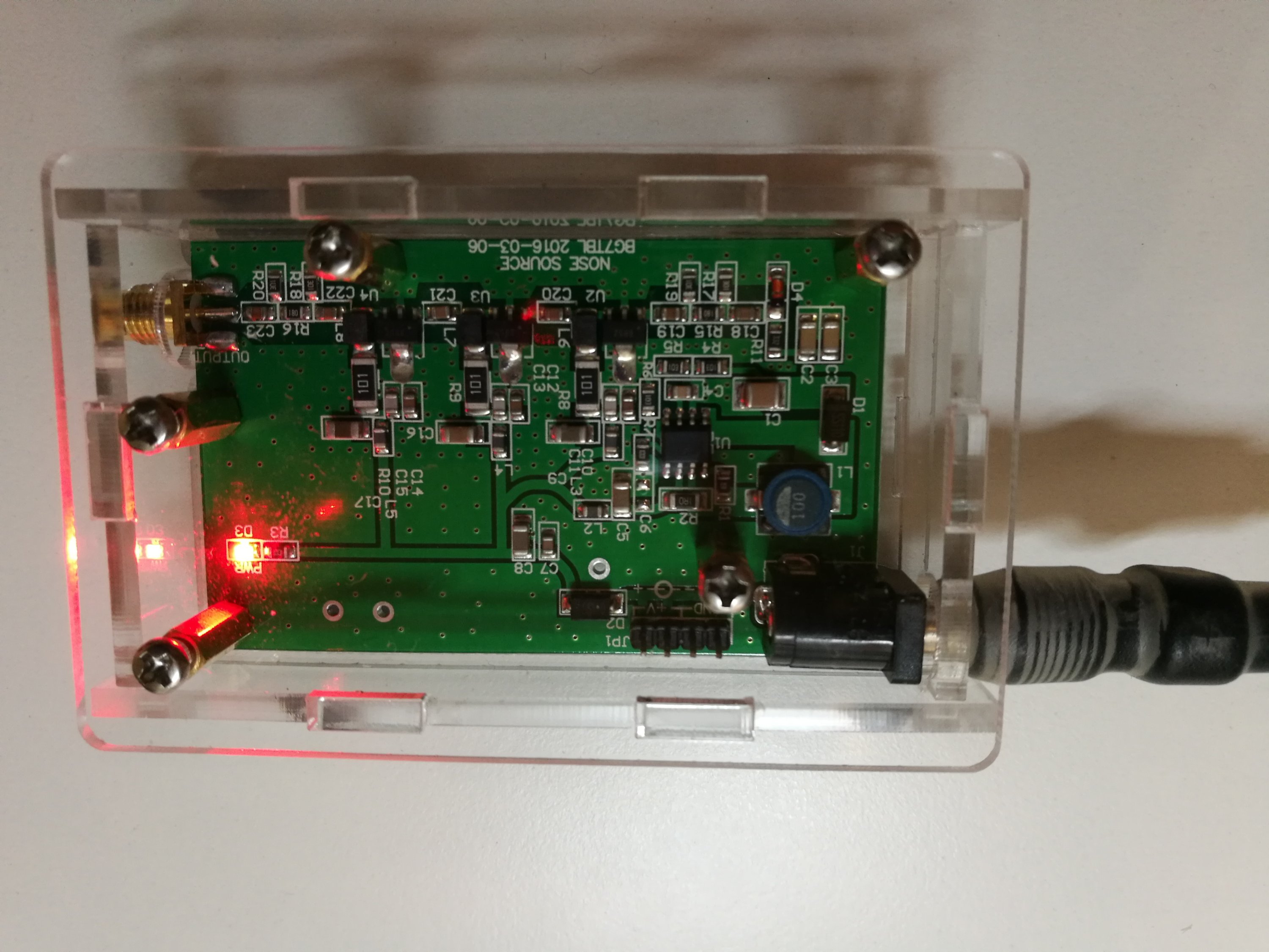
A noise source is simply a circuit that produces a very broad band of “shot noise” energy over a range of frequencies. This one is advertised to cover 200 kHz to 2 GHz and is available from eBay for $29 [2]. The circuitry is mounted in a sturdy aluminum box with 12-V power, an LED power indicator, and SMA RF output.
Now, what would one use a noise source for? Well, as an inexpensive replacement for a “tracking generator.” A tracking generator is simply an RF signal generator that produces a CW signal and tracks with the sweep of a spectrum analyzer. Many spectrum analyzers include an optional tracking generator and I always recommend clients adding this on to their purchase. I wrote an article on how to use tracking generators a few years ago [3]. They can help plot out the frequency response of an RF filter, for example.
https://www.edn.com/using-a-tracking-generator/
Tomi Engdahl says:
See how a harmonic comb generator designed expressly for testing conducted emissions #measurements performs in this #review
#EMC #test
https://buff.ly/2LL51ys
Tomi Engdahl says:
https://www.edn.com/review-com-powers-comb-generator-for-conducted-emissions/?utm_content=bufferfab4f&utm_medium=social&utm_source=edn_facebook&utm_campaign=buffer