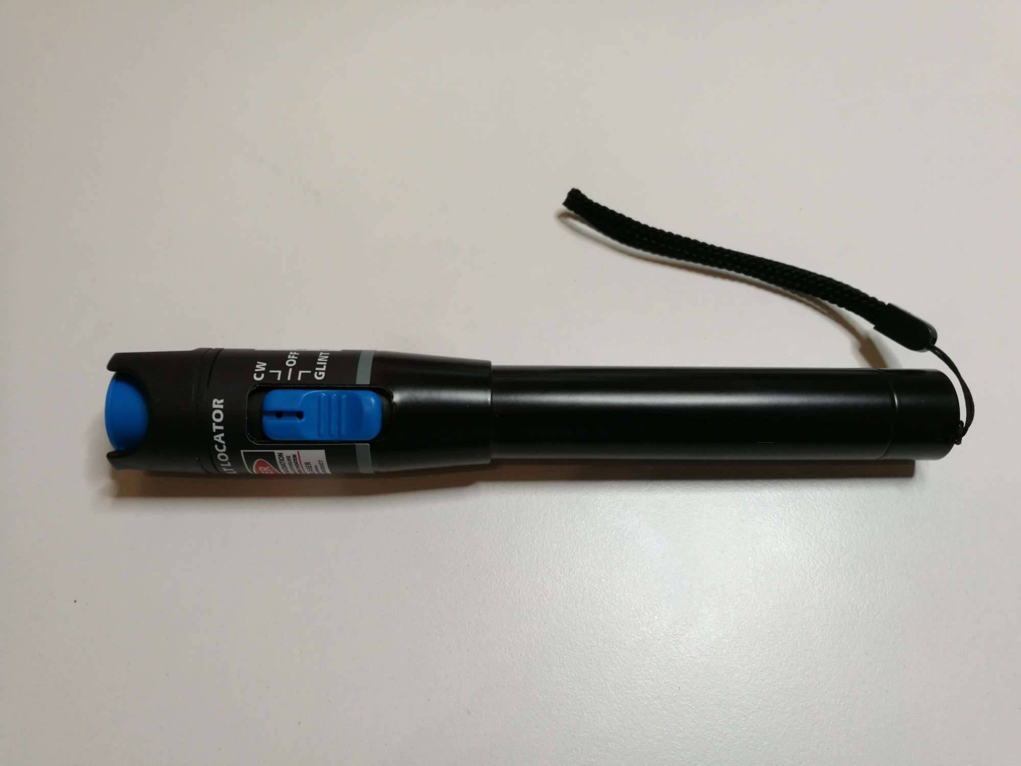
Last year I made a posting on Cheap fiber optic visual fault locator. It told about 1mW 5KM Red Light Pen Visual Fault Locator Fiber Optic Laser Cable Tester Meter puts out highly visible red light into a fiber optic cable that has ST, SC and FC optical connectors.The universal fiber connector worked well with single-mode fiber terminated with SC connector. It can also be used with bare 1 mm plastic fiber (POF).
Here are some videos on using this kind of fiber optic visual fault locator.
Pro’sKit MT-75 Series Fiber Optic Visual Fault Locator
FOA Lecture 21 Visual Fault Locator Demonstration
This is Lecture 21 in the FOA series of lectures on fiber optics. In this video, we will review the use of visual fault locators and demonstrate how they show stress loss in a typical patchcord.
FOA Lecture 22 Mode Power Distribution in Multimode Fibers
This is Lecture 22 in the FOA lecture series on multimode fibers. In this lecture we’ll briefly review modes in graded-index multimode fibers then show how you can actually see the modes by using visible laser light from a VFL (visual fault locator.) Then we will show the effect of a mandrel wrap on the fiber, allowing you to actually see how the higher order modes are removed by the mandrel wrap.
23 Comments
Tomi Engdahl says:
https://www.instructables.com/Build-a-simple-Fiber-Optic-tester/
Tomi Engdahl says:
Build a Simple Fiber Optic Tester
https://www.instructables.com/Build-a-simple-Fiber-Optic-tester/
Intro: This instructable will show you how to make a simple fiber optic cable tester for any LC style fiber.
Our DVI signal is carried over four fibers, one each for the red, green, blue and clock signals. We use LC connectors which are standard for IT infrastructure too. Our installers pull the fiber through conduit during the installation of the OR and need a quick way to verify that the fiber is good. Most testers I found were very expensive and measured db loss through the fiber. We just needed to know if it was intact or broken. I came up with this idea after looking at an LC fiber coupler and shoving a 5mm LED into it and finding out it was a perfect press fit! This tester works great for finding a broken fiber or if you have multiple fibers in an IT closet that no one has labeled (like that would ever happen…) identifying them.
Tomi Engdahl says:
How do Fiber Optic Cables Really Work?
https://www.dwarvin.com/blogs/stories/how-do-fiber-optic-cables-work
If you are like me, you learned that light travels in a straight line. So why, when I use plastic, or for that matter glass, I can make light travel around corners to where ever I like?
Refraction in Fiber Optic Cables
The answer lies in refraction. This what happens when light goes from one density of material to another. What happens is the light actually changes speed in different densities of material. Again, this may seem strange, but what we were taught at school was that the speed of light in a vacuum is a constant. What was not stressed was that in substances such as water, glass, plastic, light actually travels at different speeds, which are slower than that in a vacuum. As light takes the shortest path through a substance, this results in the bending of light as it goes from a material of one different optical density to another. relates. This is called ‘refraction’. To go into the detailed physics of this is beyond the scope of this article.
A helpful term is ‘Refractive Index’ (RI). It is a measure of the change in speed of the light, although we often think of it as describing the density of the material the light is going through. So a vacuum has an RI of 1.0, whereas that of water is 1.3, which is why we get odd effects when looking into water or from water into air. For example, you and I have experienced this so called refraction when looking into water. We look down and see an object that appears to be higher up in the water than it really is
So, what has this to do with fiber optics? Plastic or glass fibers have a fairly high RI of about 1.5. Hence, as you shine light down a plastic fiber, if the angle the light subtends to the surface of that fiber is less than the critical angle, then the light will bounce off the internal surface of the fiber and carry on down the fiber, bouncing back and forward. If the angle of the light is too large, then the light will ‘leak’ out of the fiber and be lost into the air. This is how fiber optics ‘capture’ the light inside the fiber. Providing the fiber is reasonably straight, the light will remain inside the fiber. Of course, fibers are used to take light around corners, which raises the question, how much of a bend will a fiber withstand before substantial amounts of light will leak out of it. This leads to a discussion of the ‘Maximum Bend Radius’.
Maximum Bend Radius in a Fiber Optic Cable
The question is, how steep a corner can the light be bent around? There must be some limit – and yes there is. As one bends a fiber light starts to leak out as the bend exceeds a critical level. It’s rather like taking the above diagram and tilting the right half down. The further that is tilted the blue line on the left half will eventually become the red line on the right half and eventually the green one. There is a rule of thumb.
It is that the bend radius should be greater than 10 times the fiber diameter, which we will call the Bend Radius Ratio. This is used as a guide in all glass fiber optic communication applications in which the wavelengths of light are in the infrared – i.e. wavelengths in the 1,300nm range. So does this need to be modified for much shorter wavelengths in the visible 500nm range? Published papers reveal that there is quite a strong wavelength dependency in the infrared range, however, there is nothing published for the visible range
Using the ‘rule of thumb’ would mean that for a 1mm fiber the maximum bend radius should be 10mm, or just under 1/2”, and for a 1.5cm fiber it should be 15mm just over 1/2”. My experimentation (see table below) reveals that for a 1.5mm fiber, there is minimal light loss for a bend radius of about 14mm, and about 11.5mm there is a 20% light loss, resulting in a Bend Ratio of 7.5, considerably less than the rule of thumb used in the communication industry. Incidentally, a light loss of 20% is difficult to perceive.
In summary, if one is willing to accept a 20% light loss, the maximum Bend Radius for the 1.5mm fiber is 11.5mm (as against the proposed 15mm, using the typical ‘rule of thumb’) and for the 1.0mm fiber it is 7.5mm (as against the rule of thumb of 10mm).
What is Index Matching?
Index matching attempts to remove the problem of an air gap, usually by filling the gap with a fluid. As noted above, the whole reason that fiber optics is such a good conductor of light is the difference in the refractive index of the fiber compared to its surroundings. It is this that keeps the light inside the fiber. So when the light reaches the end of a fiber where there is an air interface, there is a mismatch of refractive index and a significant amount of the light will be reflected back from the fiber end. If a substance that has the same or very close refractive index is used to connect the fibers, then the loss will be minimized. The typical plastic used in a plastic fiber is PMMA and has a refractive index of 1.5. So selecting a connecting fluid that has a similar refractive index and is optically clear will be a good candidate as an index matching fluid.
As can be seen, the use of an index matching material significantly improves the connecting between the cut fibers.
Some practical comments are in order here.
Glycerin is inexpensive and readily available. However, it is very slippery which makes it a bit more difficult to hold the fibers inside a simple tube, but if a product that is specifically designed to hold the fibers together inside a tube, it can be a very good solution.
Various different commercial index matching materials are available, as in the example of the FiberFin product listed above, but these tend to be expensive for the average hobbyist, although FiberFin’s is the least expensive but prices can range as high as $75 for 1ml. Most of these are an optically clear silicone material and specifically designed for data communication applications.
Dwarvin has a specially selected silicone material that is well suited to the optical range and delivers the same results as that of other index matching materials on the market but has an element of stickiness that helps hold the fibers inside a tube.
So, by taking care in cutting the fiber, using a sleeve to hold the fibers in proximity with each other, and selecting a suitable Index matching fluid, one can readily provide a connecting solution that will meet the needs of those mentioned above, particularly those who work with modular layouts.
Tomi Engdahl says:
What Is Bend Radius and Minimum Bend Radius of Fiber Optic Cable?
https://community.fs.com/blog/why-not-use-bend-insensitive-fiber-optic-cable-to-reduce-bend-radius.html
Bend radius is the amount of bending that can occur before a cable may sustain damage or increased attenuation and limit bandwidth performance. When a fiber cable is bent excessively, the optical signal within the cable may refract and escape through the fiber cladding. Bending can also permanently damage the fiber by causing micro cracks. The result is known as bend loss: a loss of signal strength that may compromise the integrity of the data transmission.
Note: Excessive pulling tension and overly tight fasteners can also cause transmission problems and micro-bends in optical fiber cables.
The minimum bend radius is the smallest allowable radius for a given fiber optic cable to be bent around. The new standard ANSI/TIA/EIA-568B.3 sets performance specifications, minimum bend radius standards and maximum pulling tensions for 50/125-micron and 62.5/125-micron fiber optic cables. For inside plant cable, the fiber cable bend radius is 10 times the cable’s outside diameter under no pull load, and 15 times the cable’s outside diameter when subject to tensile load.
What Is Bend Insensitive Fiber Optic Cable?
Bend insensitive fiber patch cable is designed to transmit light with minimum loss even if they are bent beyond the bend radius. In these BIF optical cables, an optical “trench” – a ring of lower index of refraction material – is built into the fiber to basically reflect the lost light back into the core of the fiber, thereby minimizing data loss. Bend insensitive fiber cable offers greater flexibility in demanding environments than traditional fiber cable. It is typically used in data centers or any space constrained area where tight bends and flexibility are required. Bend insensitive fibers are available in 50/125 MMF (OM3 and OM4) and 9/125 SMF versions.
Bend Insensitive Multimode Fiber Optic Cable (BIMMF)
Multimode fiber is popular in data centers and intra-building backbones. In the era of increased connectivity, more demands on the quality and performance of link components become more critical. New bend insensitive multimode fiber minimizes bend-induced attenuation, which helps maximize system reliability and minimize downtime. These BIMMF cables are available in all laser optimized grades, OM2, OM3 and OM4, and exhibits 10 times less signal loss in tight bend scenarios. The fiber can be installed in loops as small as 7.5mm radius with less than 0.2dB bending loss at 850nm and 0.5dB at 1300nm.
Bend Insensitive Single-mode Fiber Optic Cable (BISMF)
In 2007, a new type of “bend-insensitive” single mode fiber was introduced. It can withstand stress from bending, twisting, or stretching without suffering significant performance loss. ITU recommendation G.657 specifies two classes of single mode bend insensitive fiber patch cables: G.657 A and G.657 B. The minimum bend radius of G.657. A1 fibers is 10mm, of the G.657. A2 and G.657.B1 fibers is 7.5mm and of the G.657.B2 fibers is 5mm.
Compatibility of Bend Insensitive Fiber Optic Cable
Bend insensitive fiber optic cable has so many advantages. One question may arise: are these BIF optical cables compatible with regular fibers? The answer seems to be yes for all SMF cables. Since only one mode is guided in the core, the trench has a minimal impact on system performance and measurement. But for MMF cables, it is less clear. Measurement of core size, differential mode delay (DMD) and bandwidth was developed prior to the introduction of BIMMF designs. These measurements are in the process of being evaluated and updated so measurement results may depend on the manufacturer of the BIMMF.
Tomi Engdahl says:
https://www.academia.edu/3296571/Light_leakage_in_optical_fibers_experimental_results_modeling_and_the_consequences_for_solar_concentrators
Tomi Engdahl says:
Should You Be Worried About Bending A Fiber Cable?
https://www.garlandtechnology.com/2013/12/06/should-you-be-worried-about-bending-your-fiber-cables
Fiber wires lose light no matter what. They have a db/km loss rate, this is subject matter we have covered in my other blog on Split Ratio & Budget Light Loss.
But, did you know your bend radius could affect the db loss of a fiber cable?
There is a lot of engineering, research and development that goes into building fiber network hardware. Today I’m talking about passive fiber network TAPs and the bend radius of a fiber cable.
Bend Loss Factors
Bend loss occurs when the fiber cable bends is tighter than the cable’s maximum bend tolerance. Bending loss can also occur on a smaller scale from such factors as:
Sharp curves of the fiber core
Displacements of a few millimeters or less, caused by buffer or jacket imperfections
Poor installation practice
Microbending: losses are due to microscopic fiber deformations in the core-cladding interface caused by induced pressure on the glass.
Tomi Engdahl says:
Light leakage in optical fibers: experimental results, modeling and the consequences for solar concentrators
https://www.sciencedirect.com/science/article/abs/pii/S0038092X01001001
Tomi Engdahl says:
Bend radius: Protecting fiber optic cable from signal loss prevents network disruption
https://amphenol-ns.com/Blog/post/bend-radius-protecting-fiber-optic-cable-from-signal-loss
Today’s high-speed networks thrive on optical fiber connections … perfect fiber connections. But those connections are finicky. Fiber cable connections must be clean on both ends, they require gentle handling and they need to be installed with proper bend radius, end to end, to prevent any induced loss issues.
With the advent of 10, 20, 40 and 100 gigabyte speed connections, our wireless and content networks are trying to keep up with end users’ insatiable need for speed.
Tomi Engdahl says:
https://www.quora.com/If-I-hook-up-a-laser-pointer-to-a-fiber-optic-cable-so-I-can-bend-the-wire-around-obstacles-will-the-beam-exit-the-optics-end
First, the fiber optic can’t “bend around obstacles.” You have to make large loops to prevent bending the cable too tightly. You will have terrible losses and break the glass if you bend it into a corner smaller than about the size of of a pumpkin pie.
Second, a laser pointer might not have a good enough beam quality to couple into a fiber without severe losses. Coupling into a fiber requires precision alignment and high quality optics, well beyond the average experimenter. How do you move the fiber by 1/10,000 inch and hold it there? Usually this is done with expensive optical positioners. After you get it in place, you can glue it with UV optical index matching epoxy.
Third, if you get all of the above stuff worked out, yes, what is left of the beam will exit the fiber. However, it will spread into a very wide angle like a very bad flashlight unless you get precision collimating optics on the output end of the fiber matched to your laser. This is usually done with a gradient index of refraction lens precision cut and polished for your laser, again glued on with UV curing index matching epoxy.
Now you see why I said, if you had to ask, you probably can’t do it. The typical start up cost to get into fiber optics is over a thousand dollars, and that is really on the very low end of the scale.
You can have light exit the other end yes. But not all the light. Loss sources abound in this arrangement
The angle of the beam to the core of the fiber has to be very matched very precisely or energy will be lost.
The core of the fiber is only a few microns, the lateral alignment to the core has to be perfect
Loss will occur if the beam is larger than the core
loss will occur when the beam hits air, and then again when the beam enters glass because of index matching issues
loss will occur in the fiber due to using visible light (laser pointers are all visible) whereas the minimum losses in fiber are for infrared
some losses also occur for sharp bends
if the exit is to air then there will be losses going from the glass to air
Tomi Engdahl says:
How to use Bob Laser’s pen shaped 650nm red laser visual fault locator?
https://www.youtube.com/watch?v=8ufDKwHse6E
This is Boblaser’s pen shape visual fault locator.
It needs two triple-A batteries, install them in the compartment.
There are a dust cap in the front. Press down the top button to turn on the unit, then push the white button to switch between three modes: steady continuous mode, fast flashing mode, and slow flashing mode.
It has a 2.5mm universal adapter that works with SC, ST, and FC connectors. Let’s try on the ST connector first.
Tomi Engdahl says:
How to: Use Visual Fault Locator (VFL)
https://www.youtube.com/watch?v=wxkmdkihIO4
How to Use Visual Fault Locator (VFL) to Find Breaks in Fiber Cable? | FS
https://www.youtube.com/watch?v=H5jGPOqQBJo
Tomi Engdahl says:
How to use an visual fault locator to detect problem in your fiber cable?
https://www.youtube.com/watch?v=cQbyFEktI1U
Tomi Engdahl says:
What are the uses of Visual Fault Locator?
https://www.sopto.com.cn/sp_news/show-3517.html
As the application of optical fiber in network communication becomes more and more widespread, various optical fiber devices have emerged at the same time. Visual fault locator is one of the commonly used optical fiber inspection tools for troubleshooting network faults. Visual Fault Locator is also called light pen, pen-type red light source, visible light detection pen, fiber fault detector, fiber fault locator, etc. It is driven by a constant current source to emit a stable red light, and it is connected to the optical interface to enter the fiber to quickly detect the light. Connectivity and locate fiber failure points.
Visual Fault Locator is divided into 5Km, 10Km, 15Km, 20Km, 25Km, 30Km, 35Km, 40Km, etc. according to its shortest detection distance. The structure of Visual Fault Locator is mainly divided into battery compartment, laser, indicator light, switch, dust cap and Battery cover, etc.
Precautions for using Visual Fault Locator
1. Laser is harmful to eyes, avoid exposure to human or animal eyes
2. If the brightness of the laser beam is severely reduced, please charge or replace the battery.
3. High temperature will affect the service life of Visual Fault Locator, so Visual Fault Locator should avoid high temperature working environment as much as possible and store it in a cool and dry place.
4. Wear a dust cap in time when not using Visual Fault Locator to prevent dust and other pollution
5. Please take out the battery when not in use, and put it out of the reach of children
How to choose fiber optic visual fault locators?
https://www.fiberoptics4sale.com/blogs/wave-optics/how-to-choose-fiber-optic-visual-fault-locators
What are fiber optic visual fault locators?
Many of the problems in connection of fiber optic networks are related to making proper connections. Since the light used in systems is invisible infrared light (IR) beyond the range of the human eye, one cannot see the system transmitter light.
A Visual Fault Identifier (VFI) or Visual Fault Locator (VFL) is a visible light source (incandescent bulb, LED or laser diode) that injects visible light energy into a fiber.
By injecting the light from a visible source, one can visually trace the fiber from transmitter to receiver to ensure correct orientation and check continuity besides.
Sharp bends, breaks, faulty connectors and other faults will “leak” the light allowing technicians to visually spot the defects.
The VFI/VFL is an ideal tool for locating a large number of defects that occur at connection points in and around fiber cabinets which are hidden in an OTDRs “blind-spot” or dead-zone.
Fosco Connect offers VFI units for both single-ferrule and multi-ferrule connector styles.
Other names of visual fault locators
There are many other names for visual fault locator, such as:
Fiber Tracers
Visual Fault Finder
Visual Fault Indicator
Visual Fault Identifier
Visual Fault Detector
Visual Fault Light
Visual Fault Locator Pen
A visual fault locator emits a bright beam of red light easily visible from a distance. Connect it to one end of a fiber then locate that fiber at the other end, even if it is one of many fibers either in a cable or terminated in a rack.
Perform simple end-to-end continuity checks. Verify the proper polarity and orientation of fibers within a multi-fiber connector like the MT-RJ.
A visual fault locator can quickly illuminate fiber breaks, damaged connectors on patch cords, defective splices in splice trays, and tight fiber bends in and around equipment racks.
The choice of a continuous wave output mode for steady fault illumination or a flashing output mode makes for easier fault location.
The integrated universal 2.5mm adapter makes for easy connection to SC, ST, FC, and FJ connectors. The optional 1.25mm adapter allows for connection to LC and MU connectors.
Attach the visual fault locator to your belt using a lanyard so it is always on hand when you need it.
Visual Fault Locator’s Powers, Distances and Eye Safety
The useful operating range of fiber optic visual fault locators is widely misquoted, with ranges of 20, 30, 40 and even 50 Km often incorrectly stated.
This is what they will actually do. There is no magic, it’s just a combination of emitted power, attenuation and eye sensitivity, combined with eye safety limits on emitted power when no connector is attached (which is often not quoted at all).
VFL range under ideal conditions Power level connected “Connector end view” continuity “Break location” in patch lead “Side glow” continuity
Class 1 Legal Limit +3 dBm 10 Km 7 Km 5 Km
Class 2M Legal Limit +10 dBm 11.2 Km 8.2 Km 6.2 Km
Illegal VFL “20Km” +20 mW / 13 dBm 11.7 Km 8.7 Km 6.7 Km
Illegal VFL “30Km” +30 mW / 14.8 dBm 12 Km 9 Km 7 Km
Illegal VFL “40Km” +40 mW / 16 dBm 12.2 Km 9.2 Km 7.2 Km
Illegal VFL “50Km” +50 mW / +17 dBm 12.4 Km 9.4 Km 7.4 Km
Visual fault locator maintenance
Cleaning all connectors before coupling them to a visual fault locator.
Users should always cover the output port with the dust cap when the instrument is not in use.
If binding or stickiness is felt when inserting connectors into the output port, the ceramic sleeve should be cleaned
To clean the sleeve, insert a one-click cleaning gun into the output port until it stops. Twist the wand, remove it, and discard.
Do not reuse the cleaning wand. Do not blow air into the output port to remove dirt particles. Doing so will only pack the dirt and make it harder to remove.
Tomi Engdahl says:
Visual Fault Locator Tutorial: Everything You Need to Know
https://community.fs.com/blog/visual-fault-locator-tutorial.html
Visual Fault locator (VFL) is a basic fiber optic for troubleshooting fiber optic link. It is a must-have test gear in every fiber technician’s tool box. Read on to get information if you are:
New to virtual fault locator and willing to know what VFL can be used for;
Prepare to purchase visual fault locators but do not know how to choose;
Searching for the user guide and maintenance tips of VFL.
What Is Visual Fault Locator?
Visual Fault Locator which can be also called visual fault identifier (VFI), fiber fault locator, fiber fault detector, etc, is a visible laser available in red laser light and designed to inject visible light energy into an optical fiber. It is a cost-effective way to spot defects of fiber glass such as sharp bends, breaks, faulty connectors and other faults which will “leak” red or green light visually. It can also locate the fault of OTDR dead zone and make fiber identification from one end to the other end. No matter for installing new fibers or troubleshooting the existing networks, visual fault identifier is a helpful handy kit.
You can diagnose fiber link problems over fiber optic cables or fiber cable pigtails using visual fault locators. When the fiber fault locator is designed with adapter incompatible with your connector type, using additional adapters is necessary.
How Does Visual Fault Locator Work?
The working principle of fiber optic visual fault locator is as follows: The VFL fills the core of the optical fiber with light from the laser. The light from the laser escapes the optical fiber at a break or macrobend and will typically illuminate the buffer surrounding the optical fiber. Though macrobends are not always visible through the jacket, they are typically visible through the buffer. While breaks may be visible through the jacket of the fiber optic cable depending on jacket color, thickness, number of optical fibers in the cable, and amount of strength member.
Important Parameters of VFL: How to Choose Ideal Visual Fault Locators?
Fiber distance
The fiber distance spec tells the longest fiber length where you can still see the leakage light without difficulty. This spec is determined by the laser light power. The industry standard spec is 10km for multimode fibers and 5km for single mode fibers. FS high power 30mW fiber optic fault locator enables up to 15km dynamic distance.
Output power
Output power is an important spec for visual fault identifiers. Some may ask how many power do I need? The key is: The higher output power is, the longer fiber distance it can support. This spec is usually 0.5mW coupled to single mode fibers and 2mW to free space (which means no fiber coupling, just the light output from the tester’s connector adapter).
Fiber mode
All visual fault locators can work with both single mode and multimode fibers. Since multimode fiber has a 50um or 62.5um core, which is much bigger than single mode fiber’s 9um core, more light power can be coupled in to multimode fibers. That translates to longer fiber distance for multimode fibers than single mode fibers.
Modulation frequency (CW and 2Hz)
Human eyes are much more sensitive to blinking light than to a steady light. So visual fault locators provides two operating modes: continuous wave and pulse light. In most cases, fiber optic installation technicians prefer the pulse light mode which turns the laser source on and off in 2Hz or 1Hz frequency.
Battery
Usually two AAA or two AA alkalescence batteries are used.
Wavelength
Wavelength is not a critical spec. 635nm, 650nm and 670nm will all work just fine.
Precautions of Using Visual Fault Locators
Never look into the path of the Laser Beam and never look into the end of a fiber.
Keep away from water, dust, static electricity, and environments of extreme temperature.
Remove the batteries for prolonged periods of storage.
Never launch visual fault locator into active equipment or microscope.
Make sure that the end opposite the Visual Fault locator is not connected to any electronics or active equipment during termination.
Tomi Engdahl says:
Fiber Optic Cable Types: Single Mode vs Multimode Fiber Cable
https://community.fs.com/blog/single-mode-cabling-cost-vs-multimode-cabling-cost.html
Although single mode fiber (SMF) and multimode fiber (MMF) optic cable types are widely used in diverse applications, the differences between single mode fiber and multimode fiber optic cables are still confusing. This article will focus on the basic construction, fiber distance, cost, fiber color, etc., to make an in-depth comparison between single mode and multimode fiber types.
Tomi Engdahl says:
Fibre Laser Diode Module teardown
https://www.youtube.com/watch?v=LxrbX-YcdZU
Tomi Engdahl says:
Laser to Fiber Coupler with Receptacle Instruction Video
https://www.youtube.com/watch?v=ahDbh5UrwNc
Tomi Engdahl says:
High power fiber coupled laser diode teardownHigh power fiber coupled laser diode teardown
https://www.youtube.com/watch?v=eD2KMd2FxOo
Tomi Engdahl says:
Setting Up a Pigtailed Butterfly Laser Diode (Viewer Inspired) | Thorlabs Insights
https://www.youtube.com/watch?v=LAixCOso-FE
Tomi Engdahl says:
Coupling a LASER into a single mode fiber
https://www.youtube.com/watch?v=kQvhbJbDG0M
Tomi Engdahl says:
Optical Fiber Coupling
https://www.youtube.com/watch?v=HdiPLsokrrc
Tomi Engdahl says:
Thorlabs Fiber Coupler and WDM Manufacturing Capabilities
https://www.youtube.com/watch?v=WfbYfAe41mY
Tomi Engdahl says:
https://hackaday.com/2022/12/09/properly-pipe-laser-light-around-with-homebrew-fiber-couplings/