Interesting new micro-controller board and custom chip from Raspberry Pi: Raspberry Pi Pico.
It is programmable with Python and C/C++. Cross-platform toolchain for development on Windows, macOS, and Linux — including, naturally, the Raspberry Pi family itself Supports TensorFlow Lite.
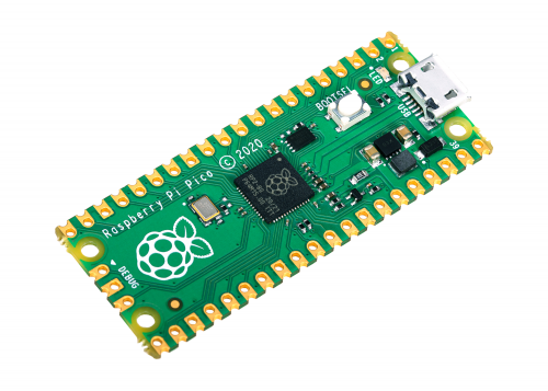
Raspberry Pi is looking to do for the microcontroller market what they’ve already done for single-board computers with the launch of the Pico. The board — priced at just $4 — is based on the RP2040, a dual-core Cortex-M0+ processor designed in house. It designed to be easy to taken into use.

Announcement at Facebook says:
It’s been a big week. We launched something tiny, something new – Raspberry Pi Pico, just for you.
Read all about it, plus everything else that went down at Raspberry Pi in the last few days, in Raspberry Pi Weekly.
https://www.raspberrypi.org/weekly/raspberry-pi-pico-has-landed/
Raspberry Pi’s just-announced Pico board! Powered by RPi’s first custom silicon, the RP2040, this little board breaks out 26 GPIO pins and is designed to be embeddable. Let’s take a look!
More information:
https://www.hackster.io/news/hands-on-with-the-rp2040-and-pico-the-first-in-house-silicon-and-microcontroller-from-raspberry-pi-effc452fc25d
https://www.raspberrypi.org/blog/raspberry-pi-silicon-pico-now-on-sale/
https://www.raspberrypi.org/documentation/pico/getting-started/
https://projects.raspberrypi.org/en/projects/getting-started-with-the-pico
https://github.com/raspberrypi/pico-tflmicro
https://www.hackster.io/gatoninja236/raspberry-pi-pico-hackster-spotlight-69ccb1
https://www.hackster.io/news/hands-on-with-the-rp2040-and-pico-the-first-in-house-silicon-and-microcontroller-from-raspberry-pi-effc452fc25d
776 Comments
Tomi Engdahl says:
Mark Washeim’s Midi Billow Is a Raspberry Pi RP2040-Powered Python-Programmable Pocket Mellotron
New upgrade to the original Billow delivers MIDI control over the cassette tape’s motor, in the same compact form factor
.https://www.hackster.io/news/mark-washeim-s-midi-billow-is-a-raspberry-pi-rp2040-powered-python-programmable-pocket-mellotron-9ff00849c956
Tomi Engdahl says:
HYDRAMeter
Open-source multimeter with some unique features
https://hackaday.io/project/176607-hydrameter
https://hackaday.com/2024/12/25/open-source-multimeter-raises-the-bar-for-diy-tools/
Tomi Engdahl says:
https://hackaday.com/2024/12/23/a-pi-pico-makes-a-spectrum-laptop/
Tomi Engdahl says:
https://hackaday.com/2025/01/04/pi-pico-makes-sstv-reception-a-snap/
Tomi Engdahl says:
Kai Gossner’s I3C Blaster Turns a Raspberry Pi Pico Into a Handy USB to I3C Bridge
If you’re looking to play with MIPI’s successor to I2C on a tight budget, the I3C Blaster is for you.
https://www.hackster.io/news/kai-gossner-s-i3c-blaster-turns-a-raspberry-pi-pico-into-a-handy-usb-to-i3c-bridge-e371c50039e0
Tomi Engdahl says:
Raspberry Pi Pico: DS1307 RTC Module – Keep Track of Time (MicroPython)
In this guide you’ll learn how to interface a DS1307 RTC module with the Raspberry Pi Pico programmed with MicroPython. We’ll cover the basic functioning of the module, how to connect it to the Pico, how to set and keep track of its time. Finally, we’ll create a simple digital clock with an OLED display.
https://randomnerdtutorials.com/raspberry-pi-pico-ds1307-rtc-micropython/
Tomi Engdahl says:
https://www.cnx-software.com/2025/01/23/hackcable-is-a-wireless-enabled-usb-c-keystroke-injection-cable-powered-by-esp32-or-rp2040/
Tomi Engdahl says:
JTAG & SWD Debugging On The Pi Pico
https://hackaday.com/2025/01/18/jtag-swd-debugging-on-the-pi-pico/
[Surya Chilukuri] writes in to share JTAGprobe — a fork of the official Raspberry Pi debugprobe firmware that lets you use the low-cost microcontroller development board for JTAG and SWD debugging just by flashing the provided firmware image.
https://github.com/dst202/JTAGprobe
Tomi Engdahl says:
https://www.raspberrypi.com/news/raspberry-pi-pico-brings-junked-joysticks-back-to-life-the-magpi-146/
Tomi Engdahl says:
Add A Little WOPR To Your Server Rack
https://hackaday.com/2025/02/19/add-a-little-wopr-to-your-server-rack/
Like so many of us, [aforsberg] found themselves fascinated with the WOPR computer from WarGames — something about all those blinking LEDs must speak to nerds on some subconscious level. But rather than admire the light show from afar, they decided to recreate it at a scale suitable for a 1U server rack.
So what goes into this WOPR display? In this case, the recipe simply calls for three MAX7219 dot matrix LED modules and a Raspberry Pi Pico, although you could swap that out for your favorite microcontroller if you wish. You should probably stick with something that at least runs MicroPython though, or else you won’t be able to use the included Python code to mimic the light patterns seen in the film.
1U Rack mount WOPR LEDs Enclosure
https://www.printables.com/model/1167457-1u-rack-mount-wopr-leds-enclosure
Description
I’ve always been deeply fascinated with the aesthetic of WOPR, the computer from War Games (1983). The steadily changing lights that allegedly represented the state of the machine are something I’ve wanted to replicate in my server rack for years. Recently I decided that if the product didn’t exist, I’d make it.
After some recon, I learned about little 8×8 LED arrays, with the MAX7219 driver. For under $10, a 1×4 array of these arrays could be had…. and you can daisy chain them together. Three of these linked in a row fit neatly into a 1U slot.
I wired them up to a Raspberry Pi Pico running MicroPython, followed a guide to get the pins in the right spot and add the basic driver and run some demos, all seemed well. The issue is that I didn’t wan this to do anything normal: I wanted to individually control each “pixel” and do my best to replicate how WOPR looked.
Tomi Engdahl says:
https://hackaday.com/2025/02/20/pico-gets-a-speed-bump/
Tomi Engdahl says:
https://blog.adafruit.com/2025/02/26/new-product-snap-on-enclosure-for-raspberry-pi-pico-w-2-2w/
Tomi Engdahl says:
https://www.hackster.io/news/the-raspberry-pi-rp2040-gets-a-surprise-speed-boost-unlocks-an-official-200mhz-mode-d6c9d267de5a
The Raspberry Pi RP2040 Gets a Surprise Speed Boost, Unlocks an Official 200MHz Mode
Spec sheet change brings a faster clockspeed than the 150MHz RP2350 — though both can, in many cases, run even faster out-of-spec.
Raspberry Pi has released a new version of its pico-sdk software development kit for the RP2040 and RP2350 microcontroller families — and it comes with a speed boost for the RP2040, bumping its maximum rated clock speed to 200MHz.
“RP2040 has now been certified to run at a system clock of 200MHz when using a regulator voltage of at least 1.15 volts,” explains Raspberry Pi’s Graham Sanderson of the performance bump in the latest SDK release. “With this version of the SDK, you can now select a 200MHz clock for RP2040 simply by setting SYS_CLK_MHZ=200 via preprocessor define. The regulator voltage will automatically be raised for you if necessary.”
Tomi Engdahl says:
https://www.raspberrypi.com/news/hexboard-midi-controller-strikes-a-chord-with-rp2040/
Tomi Engdahl says:
https://www.hackster.io/Arnov_Sharma_makes/pico-studio-light-4eac11
Tomi Engdahl says:
https://www.hackster.io/news/carlos-escobar-brings-micropython-to-the-msx-family-by-swapping-the-z80-for-a-raspberry-pi-pico-118f8f1a968b
Tomi Engdahl says:
Pico Indicator adds LEDs to GPIO and power signals of the Raspberry Pi Pico and compatible boards
8086 Consultancy has designed a simple board called the Pico Indicator to add LEDs to the GPIO and power pins of the Raspberry Pi Pico and other boards with the same pinout.
https://www.cnx-software.com/2025/03/28/pico-indicator-adds-leds-to-gpio-and-power-signals-of-the-raspberry-pi-pico/
Tomi Engdahl says:
https://hackaday.io/project/198914-not-an-ethernet-transceiver
Tomi Engdahl says:
https://www.hackster.io/MrRobotElectronics/mintypipico-tiny-video-game-pcb-version-d8e946
Tomi Engdahl says:
https://www.hackster.io/news/micromac-raspberry-pi-pico-macintosh-emulator-kit-bb6592045cc0
Tomi Engdahl says:
https://hackaday.com/2025/04/28/pi-pico-throws-us-for-a-midi-loop/
Tomi Engdahl says:
https://www.cnx-software.com/2025/05/13/picoemp-a-raspberry-pi-pico-based-open-source-electromagnetic-fault-injector-designed-for-emfi-testing-and-research/
Tomi Engdahl says:
https://www.xda-developers.com/raspberry-pi-pico-projects-cost-under-10/
Tomi Engdahl says:
https://hackaday.com/2025/04/25/rp2040-spins-right-round-inside-pov-display/
Tomi Engdahl says:
https://hackaday.com/2025/05/20/pentapico-a-pi-pico-cluster-for-image-convolution/
Tomi Engdahl says:
https://github.com/bkw777/peeko