Mains power EMI noise filtering

Because of the presence of mains current in mains-powered audio equipment as well as ubiquitous AC electromagnetic fields from nearby appliances and wiring, 50/60 Hz electrical noise can get into audio systems, and is heard as mains hum from their speakers.

In addition to mains frequency humming, the mains power can also contain higher frequency noise that is often referred as EMI (Electromagnetic Interference) noise. Problems range from straightforward ‘hums’ (which normally include various levels of the mains harmonics, such as 50Hz, 100Hz, 150Hz, and so on in the UK, or 60Hz and higher multiples in the US), to a wide range of scratches, ticking, buzzing and other digital gremlins.

Don’t let buzz, hum, or hiss ruin your AV experience. Check that your wiring is is right and after that if problem persists turn to look mains power quality. It’s only worth ‘cleaning up the power signal’ if it’s dirty, and a huge number of background noise problems are caused not by mucky mains, but by audio wiring that results in ground loops. This is the source of lots of unwanted nasties that sneak into your audio signals.

There are many products advertised to help power noise issues. Advertised tools include mains filters, isolation transformers. UPS devices and even special power regeneration devices. Slightly cheaper than an online UPS, but absolutely effective against all kinds of line noise is an isolation transformer.

To get idea of mains power noise take a look at Electrical noise on your power line video

One EMI meter that is commonly used to measure mains power noise is Greenwave Broadband EMI Dirty Electricity Meter sold at Amazon. Greenwave Broadband EMI Dirty Electricity Meter measures the dirty electricity (a.k.a. electrical noise, line noise, power line EMI) present on the wiring in buildings. It is designed to easily compare EMI levels before and after installing dirty electricity filters. Simply plug the meter into electrical outlets to get measurements. This instument says that it measures a broad range of dirty electricity frequencies at approximately 3 kHz — 10 MHz frequency range. The meter includes a speaker that lets you listen to the dirty electricity on a circuit and hear noise to decrease as filters are installed.

Listen To Dirty Electricity with Greenwave EMI Meter. Hear the Difference Greenwave Filters Make!

There are also other mains EMI meter brands. Ebay sells also OLED Digital AC Noise Meter EMI Tester Wideband AC Power Ripple Analyzer and similar.

There are many companies that sell mains filters that promise to make wonders in the mains power filtering. Not all of them seem to live up to their promises, and it seems you need to be careful what you buy. And you should test the product before buying.

PS Audio is selling incredibly small and advertised to be effective noise harvesting instrument converts damaging line noise into harmless light. Their video What’s a Noise Harvester? tells about the product and promises a lot:

The question is if PS Audio’s product is incredibly small and effective noise harvesting is as effective as promised. How does it work and how effective is it? It seems that based the on several tests it is not very effective.

PS Audio Noise Harvester Review (AC Filter)

In the video above Amir dropping the Hammer on the Snake Oil. According to this video this looks like to be true snake oil…that real living snakes.. wouldn’t want to go near..but some audiophiles… really like snake oil.

Does PS Audio Noise Harvester Really Work For Cleaner Electricity video shows a quick test to show whether or not it really does what the manufacturer says it does.

Video comments: Ps audio, ” it does something “. Yes it flashes a blue light. AudioScienceReview has measured this device. Thank you for this review!

Audio Science Review on PS Audio Noise Harvester AC Cleaner Review has lots of measurement results that do not seem to be promising on this filter performance. Audio Science Review proved with measurements that this product does absolutely nothing useful. In some of the tests made the noise actually went up when you plugged in the snake oil.

Collinsaudio took some measurements and wrote a report that has also some technical details what is inside the device. If anything this devise adds switching noise, because inside there is a transistor, triac, inductor (choke) and a few caps.
“If I were to speculate on the operating principles of this device, I wouldimagine that the power line is AC coupled then applied to the primary of the toriodialtransformer. The secondary is then connected to some type ofhigh-pass filt er an d fin ally t o a mo n o-stablethat flash es the LED.While it’s somewhat hard to imagine the benefits of this type of line filter, I was unable see any objective improvement with the Noise Harvester™.”

This seems be be pretty muuch purely a psychological device. This seems to be audiophoolery specifically “designed” to rip off gullible people. Brand should be more like BS Audio.

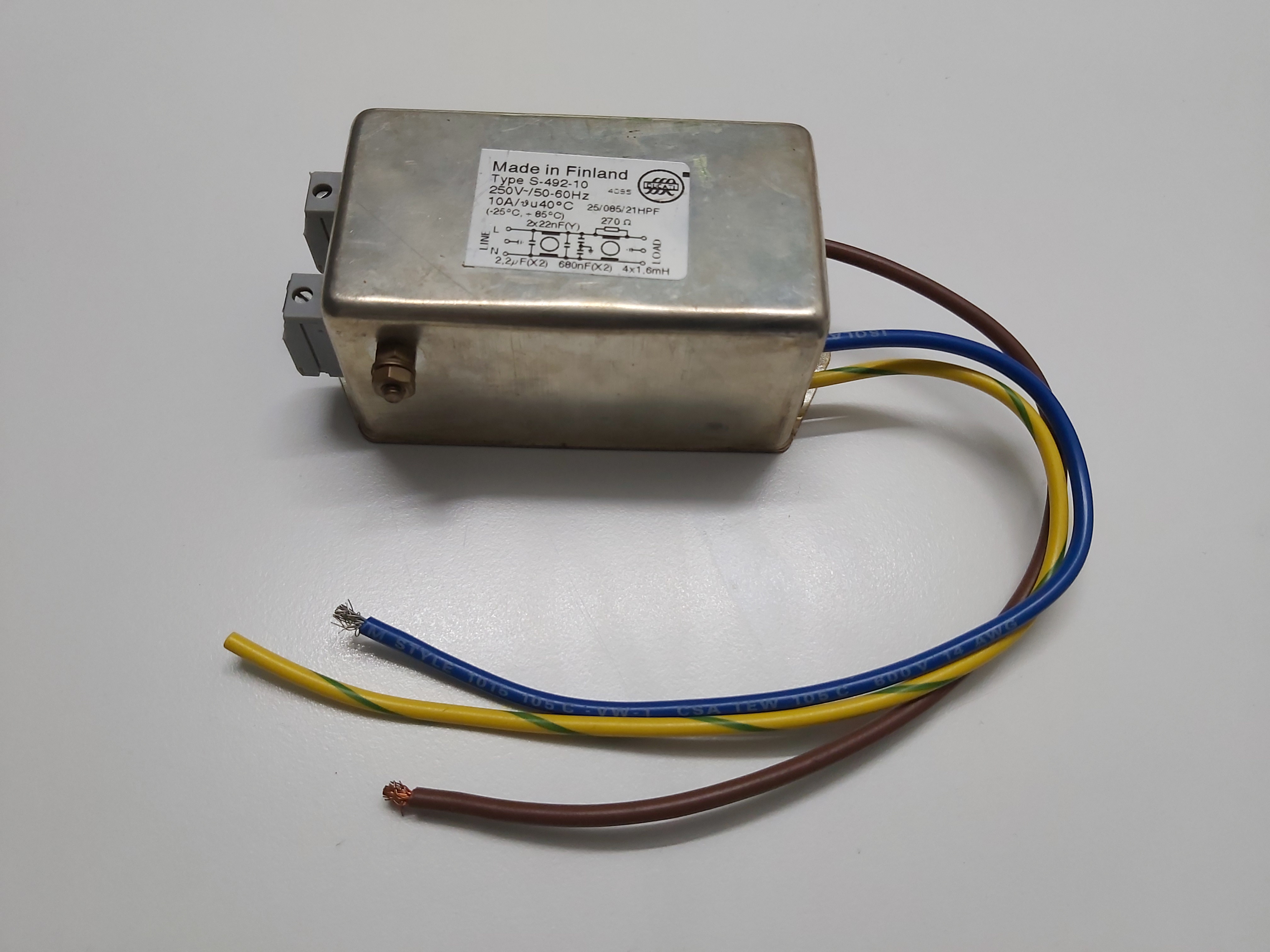
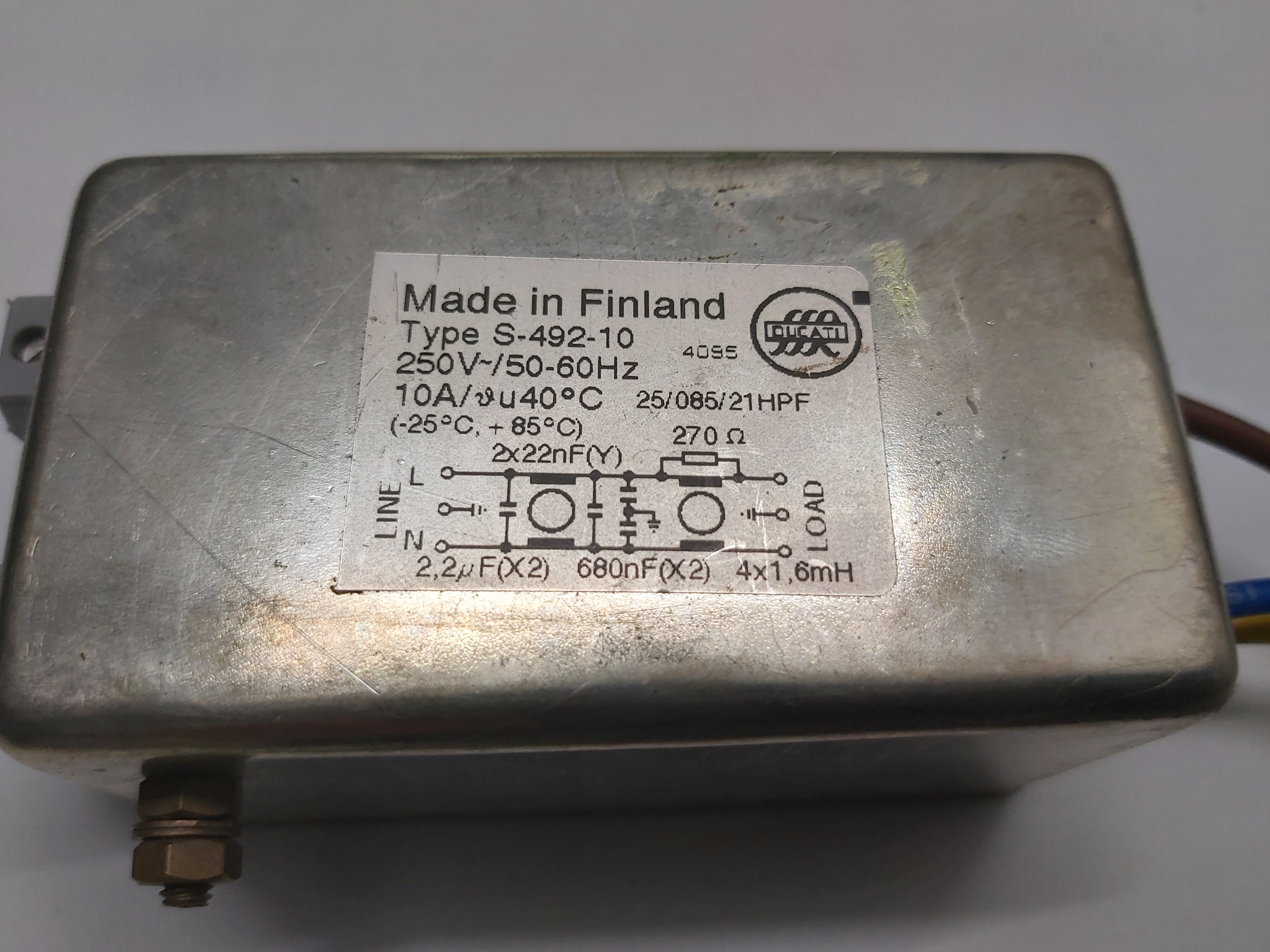
A real effective mains noise filters has power flowing through it and has several LC filter stages. Something like this:

20210302_213958

20210302_214004

95 Comments

  1. Tomi Engdahl says:

    OLED Digital AC Noise Meter Line EMI Tester Wideband AC Power Ripple Analyzer
    https://www.ebay.com/itm/124552622124?hash=item1cffea302c:g:7qoAAOSwa5RgFhGV

    The main function of this AC mains noise tester is to display the current voltage value and noise voltage value of the mains through the panel’s OLED dot matrix screen. In this way, everyone can see the current state of the mains power very intuitively, and can repeatedly compare the changes in the noise voltage between the front and the back of the electric station, and have a rational and accurate judgment on its effect. With this tester, it is easier for everyone to adjust the power supply to the best condition.

    Features:

    OLED screen displays noise voltage value and AC voltage value
    There are small speakers that can directly amplify the noise output, and judge the source by the sound to determine the size and frequency of the noise.
    Plug directly into a wall outlet (power outlet), no battery required;
    The speaker plays EMI sounds and amplitudes are demodulated to identify EMI sources (such as AM or shortwave radios, motors and arcs).

    Parameters :

    Input voltage: AC 85Vac – 250Vac 50/60Hz (accuracy +/- 1 VAC)
    Frequency range: 10KHz – 10MHz
    Noise range: 1mV – 1999mV
    Measurement accuracy: +/- 5% @ 1MHZ; +5% to -50% @ 10 KHz TO 10MHz
    Noise indication: 4 digits yellow and blue two-color OLED digital dot matrix display
    Dimensions: 132 X 91 X 41mm
    Weight: 230g

    Reply
  2. Tomi Engdahl says:

    220V LCD AC Noise Meter EMI Tester Wide band AC Power line Ripple Analyzer
    https://www.ebay.com/itm/363255685195?hash=item5493b9e04b:g:qa8AAOSwS2Bf~VZX

    220V LCD AC Noise Meter EMI Tester Wide band AC Power line Ripple

    Analyzer

    Features:

    - LCD digital screen displays AC noise values clearly

    - When noises exceed testable range, OVER-RANGE indicator turns red

    - Rotate SENSITIVITY knob and noise value varies

    - The larger the noise, the louder the speakers

    - Designed with skid-proof feet pads

    - Easy to test and upgrade your devices

    Package Included:

    - 1 x Noise Tester 220v

    - 1 x Power Cable

    Plug to unfiltered output and set sensitivity to 100. Then move plug to a filtered output to see the relative noise reduction.

    Reply
  3. Tomi Engdahl says:

    Mains Input Filters – What is Inside the Box and Why?
    https://interferencetechnology.com/mains-input-filters-what-is-inside-the-box-and-why/

    These days, it’s common practice to buy-in mains input filters in the shape of metal boxes with four or five terminals. The supplier’s lists may be consulted, and advice sought, but often the same filter as was used for a previous product is called up, without too much deliberation. A filter is a filter is a filter, after all.
    Well, no, they are not all the same. Let’s consider what we are asking the filter to do. It’s quite important at this time, because EMC requirements are being extended both upwards from the 40th harmonic of the power frequency and downwards from the historic 150 kHz lower limit of ‘high frequency emissions’. For some products, requirements already exist down to 9 kHz and there is no low-frequency limit now in the standard, CISPR 11/EN 55011, for ‘industrial, scientific and medical’ equipment, or in the new Radio Equipment Directive.
    Whiter we want it or not (but we mostly do want it), the filter acts both on energy incoming from the power system (an immunity issue) and energy leaving the product and entering the power system (an emission issue). For both flows, we have two modes: differential mode, in which a voltage appears between the two power conductors, and common mode, in which both conductors have the same voltage relative to local ground. In the case of three-phase, three-wire supplies, the filter configuration is more complicated, but for three-phase, four wire supplies, each phase is treated as if it were a single phase.

    How we can attenuate these flows depends on their source impedances. Clearly, it’s not much use connecting a capacitor across a low-impedance source to shunt current away, because plenty of current is still available, and it’s equally futile to connect an inductor in series with a high-impedance source. This is, in fact, an example of a far more general concept.

    A network representing the impedance of 230 V 50 Hz 16 A circuits in Europe from 2 kHz to 9 kHz is given in IEC 61000-4-7

    For frequencies above 9 kHz, we have the information on ‘line impedance stabilizing networks’ (LISN) or ‘artificial mains networks’ (AMN) in CISPR 16-1-2/EN 55016-1-2. For 9 kHz to 150 kHz, an impedance of 5 Ω in series with 50 µH is given, with a parallel 50 Ω resistance, while for the range 150 kHz to 30 MHz an impedance of 50 Ω in parallel with 50 µH is given. There is now a third network, for 150 kHz to 100 MHz, which is 50 Ω in parallel with 5 µH in series with 1 Ω. However, some of these values are ‘traditional’, and again tend to be the average of zero and infinity. Nevertheless, their use doesn’t result in any proposal to change them on the grounds that something else is demonstrably better.
    However, the impedance at any particular wall-socket is undetermined and may even vary, according to what other loads are on the same circuit and how the supply network is configured at that time of day. So we want our filter to be very tolerant of source impedance and not, for example, show any resonant behaviour in conjunction with any likely supply reactance.
    The impedance of the load can be very problematical. It is very often a full-wave rectifier, so extremely non-linear. We know from experience of EMC problems in the field that the circuit is transparent from the filter capacitor to the mains filter ‘output’, because if the capacitor dries out so that its capacitance drops to a much lower value, the high-frequency emissions coming from processes inside the product circuits considerably increase in amplitude, typically by more than 20 dB.

    For the ‘traditional’ frequency range from 150 kHz upwards, the sources (power network and rectifier or whatever in the product) are assumed to have high impedances, so should be faced in the filter by capacitors, between the live conductors to present a low impedance to differential mode energy , and equal values from each conductor to ground to do that for common-mode energy.
    Simple filters for low-power products therefore have a modified π configuration, (strictly an O-configuration, because it has inductors in both ‘legs’

    The inductors are rather special and are called a ‘common-mode choke’.

    Neither of these set-ups show the transformers necessary to do the 0.1 Ω/100 Ω tests.
    It is really necessary to measure filter performance in the product it is to be used in, even if it takes some ingenuity to make realistic measurements. A decision has to be made whether to include a standard Line Impedance Stabilizing Network (LISN), which assumes that the mains supply ‘looks like’ 50 Ω at high frequencies, or to use a hopefully representative supply without a network.

    Reply
  4. Tomi Engdahl says:

    Fairchild Semiconductor Power Seminar 2010-2011 1 Electromagnetic Interference (EMI) in Power Supplies
    https://emcfastpass.com/wp-content/uploads/2017/04/Electromagnetic-Interference-EMI-in-Power-Supplies.pdf

    Reply
  5. Tomi Engdahl says:

    Understanding EMI Filters: The Bare Essentials
    July 20, 2021
    Electromagnetic-interference filtering is a vital factor to delivering reliable power hardware.
    https://www.electronicdesign.com/power-management/whitepaper/21168064/electronic-design-understanding-emi-filters-the-bare-essentials

    What you’ll learn:

    Rules and standards regarding noise and EMI.
    The basic facts about, and causal factors of, EMI.
    How to implement an EMI filter in a design.

    EMI Filters Also Must Adhere to Safety Standards

    In a safe design, inductor temperature rise is usually measured. The power mains operation will control the minimum electrical spacing between line, neutral, and ground. These efforts will reduce the risk of fire and electrical shock.

    Each capacitor will need to be safety-certified, depending on their position in the circuit. Special capacitors have to be used across the power mains input terminals, as will capacitors from the ac circuit to ground.

    What Exactly is EMI, Though?

    EMI issimply noiseinterference caused by external electromagnetic waves. EMI can lead to the performance degradation of any electrical equipment design within range by inducing unwanted currents and voltages in its circuitry.

    EMI has two major components: conducted EMI and radiated EMI. Conducted EMI is coupled via conductions through parasitic impedances, power connections, and ground connections. Radiated EMI, however, is coupled through radio transmissions. It has been demonstrated that keeping the conducted differential performance in check above 30 MHz also will help meet the separately tested radiated EMI requirements

    Noise is coupled to a susceptible system via the following mechanisms:

    At low frequencies, the coupling is caused by conduction.
    At mid-frequencies, the electric and magnetic fields are the mechanisms for coupling.
    At high frequencies, the coupling is from radiation.

    Noise Interference within a System

    Even in the absence of external noise sources, outside of an electronic device, the inside circuits may cause interference with other circuits in that system. This is known as “intra-system EMI.” An example is digital circuitry emitting noise that’s induced into a wireless circuit within a smartphone, which may have difficulty receiving/transmitting wireless signals to and from a local 5G base station. Another example would be a radio that might also be affected by a motor nearby.

    Circuits of ever-higher sophistication are laid out in close proximity to other circuitry to reduce the form factor of the overall design. On-board sensitive components may be placed close to power-management circuitry with large voltages and currents. This kind of layout could lead to some circuitry interfering electromagnetically with nearby sensitive circuitry. Design layouts must achieve an adequate density of components while being sensitive to EMI interference to other, more susceptible components.

    Conclusion

    When a new product design is released to the world of electronics, it must pass specific EMI tests to meet local standards for that particular product type.

    Reply
  6. Tomi Engdahl says:

    ‘Live’ Mains Impedance Measurement and Analysis
    https://www.researchgate.net/publication/261233086_%27Live%27_mains_impedance_measurement_and_analysis

    Since the 1980-ties, the asymmetric mains impedances have been defined by IEC CISPR 16-1-2 [1] and used in an artificial mains network (AMN) suited in the frequency range (10) 150 kHz to 30 MHz. The mains impedance has recently been extended by the definition of asymmetric or common-mode artificial networks (AAN) and coupling/ decoupling networks (CDN) which are defined to be used in the frequency range 150 kHz to 80 MHz. All power mains impedances defined with these networks represent mean values from statistical data gathered and these networks are formally used to demonstrate conducted mains RF emission (and RF immunity) compliance in a defined and reproducible manner. However, other international EMC standards like IEC 61000-3-2 [4] and 61000-3-3 [5] consider mains frequency harmonic emission and flicker from the same mains wall outlet sockets with other impedances, this from the mains frequency upwards to 2 kHz. The mains impedance in the intermediate/overlapping frequency range from 2 kHz to 150 kHz is considerably less as defined by IEC 61000-4-19 [3] which is opposed to the mean values as given by IEC 61000-4-7 [2] where the mains impedances are much higher. In this paper, two ‘live’ mains impedance measurement techniques are given to obtain a detailed impedance behavior in time and/or frequency domain. Knowing the ‘real’ mains impedances means that one is able to forecast resonances and derive the optimal way on how to apply mains filters effectively, while using their appropriate parameters. Mains distribution optimization can also be used inside a large system or installation.

    Reply
  7. Tomi Engdahl says:

    10KHz-10MHz Line EMI Meter Mains Noise Analyzer EMI Measuring Device w/ OLED#
    https://www.ebay.com/itm/284397283200

    10KHz-10MHz Line EMI Meter Mains Noise Analyzer EMI Measuring Device w/ OLED Display

    Description:
    The main function of this AC mains noise tester is to display the current voltage and noise voltage of the mains through the panel’s OLED dot matrix screen. In this way, everyone can see the current state of the mains power very intuitively, and have an accurate judgment on the quality of the power supply.

    Features:
    - OLED screen displays noise voltage and AC voltage
    - There are small speakers that can directly amplify the noise output, and judge the noise intensity and frequency by sound
    - Plug directly into a wall socket (power socket)
    - The speaker plays EMI sounds and amplitudes are demodulated to identify EMI sources (such as AM or shortwave radios, motors and arcs)

    Specifications:
    - Input voltage: AC 85Vac – 250Vac 50/60Hz (Accuracy: ±1 VAC)
    - Frequency Range: 10KHz – 10MHz
    - Noise Range: 1mV – 1999mV
    - Measurement Accuracy: ±5% @ 1MHZ; +5% to -50% @ 10 KHz to 10MHz
    - Noise Indication: 4 digits yellow and blue two-color OLED digital dot matrix display
    - Dimensions: 132 x 91 x 41mm
    - Machine weight: 150g

    Package Included:
    - 1 x Mains Noise Analyzer
    - 1 x 0.8m AC Power Cable

    OLED Digital AC Noise Meter Line EMI Tester Wideband AC Power Ripple Analyzer
    https://www.ebay.com/itm/124552622124?hash=item1cffea302c:g:7qoAAOSwa5RgFhGV

    Features:

    OLED screen displays noise voltage value and AC voltage value
    There are small speakers that can directly amplify the noise output, and judge the source by the sound to determine the size and frequency of the noise.
    Plug directly into a wall outlet (power outlet), no battery required;
    The speaker plays EMI sounds and amplitudes are demodulated to identify EMI sources (such as AM or shortwave radios, motors and arcs).

    Parameters :

    Input voltage: AC 85Vac – 250Vac 50/60Hz (accuracy +/- 1 VAC)
    Frequency range: 10KHz – 10MHz
    Noise range: 1mV – 1999mV
    Measurement accuracy: +/- 5% @ 1MHZ; +5% to -50% @ 10 KHz TO 10MHz
    Noise indication: 4 digits yellow and blue two-color OLED digital dot matrix display
    Dimensions: 132 X 91 X 41mm
    Weight: 230g
    Package include Accessories: AC detachable two-core power cord, length 0.8 m

    Reply
  8. Tomi Engdahl says:

    EMI MEASUREMENT AND MODELING TECHNIQUES FOR COMPLEX ELECTRONIC CIRCUITS AND MODULES
    https://scholarsmine.mst.edu/cgi/viewcontent.cgi?article=3644&context=doctoral_dissertations

    Reply
  9. Tomi Engdahl says:

    Practical Aspects of EMI Protection
    https://www.maximintegrated.com/en/design/technical-documents/tutorials/1/1167.html

    Before applying any protective elements, consider these basic rules:

    EMI protection should be considered while designing the circuit, not added afterwards.
    Block disturbances as near to the source as possible, preferably before they enter the equipment; redirect them to ground.
    All sections that can be exposed to EMI disturbance, even electrically isolated sections, should be located as far as possible from sensitive circuitry.

    Reply
  10. Tomi Engdahl says:

    EMI Debugging with Spectrum Analyzers
    https://www.rs-online.com/designspark/emi-debugging-with-spectrum-analyzers

    Precompliance, as well as debugging tests, are most commonly done with the help of a spectrum analyzer or an oscilloscope.

    EMI Debugging with an Oscilloscope
    https://www.rs-online.com/designspark/emi-debugging-with-an-oscilloscope

    Reply
  11. Tomi Engdahl says:

    Mains frequency noise components
    https://electronics.stackexchange.com/questions/370459/mains-frequency-noise-components

    If the question is why do you see harmonics of the line frequency popping up as EMI in your measurements of a transfer function the the answer follows:

    Harmonics on the AC line are generally caused by nonlinear loads. For example, a bridge rectifier followed by a capacitor filter will cause the following kind of current waveform, as current flows only when the line voltage exceeds the capacitor voltage:

    In many parts of the world regulations require power factor correction, or more precisely harmonic elimination circuitry to mitigate (but not necessarily eliminate) the problem, but lower power (<75W for example) equipment is exempt. So in aggregate this equipment can still cause harmonic distortion on the lines.

    The IEC standard that applies is IEC 61000-3-2, which specifies the maximum allowable value for harmonic currents from the second harmonic up to the 40th harmonic current.

    Reply
  12. Tomi Engdahl says:

    how to visualize noise on AC line
    https://forum.allaboutcircuits.com/threads/how-to-visualize-noise-on-ac-line.137349/

    You can view the AC noise on the mains with a standard oscilloscope, by using a capacitor and a resistor in a highpass filter configuration (capacitor in series with resistor to ground).
    The corner frequency should be below the lowest frequency of EMI you want to see.
    If it’s 150Khz then the 60Hz will be suppressed by over 60dB for a single-pole filter.
    If you need more suppression of the mains frequency you can go to a higher order filter.

    Warning: You must have an isolation transformer between the mains and the unit under test so that the scope common and chassis won’t be at a lethal voltage, and you won’t be vaporizing a ground lead.

    ONEAC ONEView®Line Noise Viewing Interface
    http://www.gryphon-inc.com/Spec%20Sheets/Power%20Monitoring/917010A%20-%20ONEView.pdf

    The ONEView can be used with any one-, two-, or three-chan-nel oscilloscope. Using a three-channel oscilloscope will allowyou to simultaneously examine both the normal- and common-mode noise, along with the normal-mode 50/60 Hz voltagewaveform.

    Reply
  13. Tomi Engdahl says:

    https://www.diyaudio.com/forums/power-supplies/315953-measure-safely-ac-mains-pollution-noise.html

    Mains transformers are not ideal for that purpose: they degrade the frequency response above a few kHz, and distort (a little) lower frequencies.
    In general, disturbances are high frequency, which means you can get away with some short-cuts.

    One is to use a common-mode choke intended for mains purposes coupled with “Y” capacitors.

    This will result in a second order high-pass filter, useful for removing high amplitude, low-frequency voltages, and will provide a double insulation barrier for safety: one is not completely regular, because X-rated components should not be used for Y applications (unless they are certified for both, which is not uncommon), and the other, Y caps, are OK, but on their own cause earth leakage which can be annoying for metrological applications.
    If your test gear is earthed, this setup is completely safe, if properly built, of course.
    If you have doubts, ask the necessary explanations, don’t risk your life.

    Reply
  14. Tomi Engdahl says:

    Mains interference
    https://www.tmsi.com/blog/mains-interference/

    A signal that that is almost always found in an electrophysiological measurement is coming from the mains, 220 V / 50 Hz in most European countries, 110 V / 60 Hz in many others. It is a common mistake to think that if you are not connected to mains (i.e.: use a battery powered amplifier) you are free of mains interference in your measurements. There are several ways how mains can interfere with your recordings.

    Reply
  15. Tomi Engdahl says:

    Measurements of High-Frequency Noise on Power Lines and Ground
    https://www.bondline.com.au/images/uploads/images/Bondline_OnFilter_AN%20EMI%20Adapters.pdf

    High Voltage Problem Connecting your oscilloscope or a spectrum analyzer to live power line is highly problematic. The peak voltage on a 250VAC line reached 353V in each polarity, meaning that a regular 10:1 probe is insufficient to fit a complete waveform on the screen of an oscilloscope. At a minimum, a 100:1 probe is required. Even with such probes strong power line surge can still damage your instrument. Measurement Problem 100:1 probe attenuates not only power line mains voltage but all signals on power lines. High-frequency signal will also be reduced by 100 times making it difficult to measure. If you are concerned with noise of 0.5V/0.3V as specified in IPC-A-610, now you would have to deal with looking for a 5mV signal with dubious certainty.

    Blocked AC Mains Voltage MSNxxx adapters completely block 50/60Hz signal while being transparent to higher-frequency signals present on power lines. This enables measurements of only high-frequency signals without triggering or measurements problems

    Balanced Input MSNxxx adapters have completely balanced input which in combination with galvanic separation between input and output removes possibility of ground loop and allows use of AC-powered oscilloscopes or spectrum analyzers without a need for ground isolation Impedance Matching While impedance of power lines and ground at high-frequency is seldom determined, it is certainly low. MSNxxx EMI Adapters provide low input impedance for such signals without loading AC mains resulting in more accurate measurements and reduced artifacts.

    Reply
  16. Tomi Engdahl says:

    How to measure powerline quality with an oscilloscope
    https://www.testandmeasurementtips.com/measure-powerline-quality-oscilloscope/

    Modern oscilloscopes, using the Fast Fourier Transform (FFT) that is part of the Math functions, can create a frequency-domain representation resembling a bar graph that shows the harmonic content. In the frequency domain, appearing when the user presses the correct soft key, the oscilloscope redefines the axes so the X-axis shows frequency (rather than the passage of time as in the time domain). The Y-axis still shows amplitude, but now as power on a logarithmic scale (as opposed to volts on a linear scale as in the time domain). The third-order whole integer multiple of the fundamental is known as the third harmonic. This is the one that causes so much trouble in three-phase Y-configured electrical systems.

    The spectrum analyzer displays waveforms in the frequency domain. While it is not as well-rounded and diverse in its functionality as the oscilloscope, it is capable of in-depth spectral analysis over an awesome range. Advanced labs and electronics shops have both instruments.

    Reply
  17. Tomi Engdahl says:

    https://www.sciencedirect.com/topics/engineering/main-voltage

    Tim Williams, in EMC for Product Designers (Fifth Edition), 2017

    14.2.3.3 Safety considerations
    CY1 and CY2 are limited in value by the permissible continuous current which may flow in the safety earth, due to the mains operating voltage impressed across CY1 (or CY2 under certain fault conditions). Leakage current for these capacitors only can easily be calculated

    Values for this current range from 0.25 to 3.5mA depending on the applicable standard, safety class and use of the apparatus (Table 14.2). Special installation conditions apply where the leakage exceeds 3.5mA. Medical equipment has an even lower leakage requirement, typically 0.1mA. Note that this is the total leakage current due to the apparatus

    The frequently specified value of 0.75mA leakage current gives a maximum capacitance of around 4nF on each phase for a voltage of 250V at 50Hz, so something less than this value is typical in general-purpose filter units.

    Component ratings
    Both CX and CY carry mains voltages continuously and must be specifically rated to do this. Failure of CX will result in a fire hazard, while failure of CY will result in both a fire hazard and a potential shock hazard. “X” and “Y” class components to EN 132400 (similar to IEC 60384-14) are designed and marketed specifically for these positions; safety standards mandate their use. EN 132400 has various requirements (Table 14.3) including peak impulse voltage, voltage endurance and flammability.

    Bleed resistance
    Large values of CX should be protected with a bleeder resistor in parallel, to prevent a hazardous charge remaining between L and N when the power is removed, if the mains switch is placed after the filter on portable apparatus. The value of resistance is determined by its time constant with the total value of differential capacitance, such that the charge decays adequately soon after the unit is unplugged from its supply (detailed requirements can be found in safety specifications such as IEC 60335/EN 60335). One consequence of this for apparatus which must now comply with energy efficiency legislation is that the bleed resistor’s minimum value may be limited by standby power dissipation requirements; and this in turn can place a limit on the maximum value of X capacitance in the filter.

    Reply
  18. Tomi Engdahl says:

    The first step us to determine if you have a need. You will need an oscilloscope to see IF you have the type of HF getting into your power lines that this filter could solve. If you have evidence of RF getting into your AC, then you can add this device and compare if it got better. Also check the secondaries of your power transformer. It is very possible that HF can’t get through anyway!
    Audio has too many solutions looking for problems! Audio also has too many deaf and angry electricians looking to be “experts”.
    As simple as possible, only as complex as necessary.

    Reply
  19. Tomi Engdahl says:

    if there is no high frequency noise on incoming power, then no effect.
    If incoming power has lots if RF noise and equipment do not have good noise filtering built in, can improve performance considerably.

    Reply
  20. Tomi Engdahl says:

    EMI FILTER DESIGN
    The engineer’s guide to designing your EMI filter
    https://impulse.schaffner.com/en/engineers-guide-to-designing-emi-filter

    Before going to the test lab, procure different filter configurations from a commercial filter company to have on hand during testing. If the original one doesn’t pass, then change over to an alternate one. Having them on hand will shorten the development time and save on test lab cost due to multiple revisits.

    Reply
  21. Tomi Engdahl says:

    Understanding EMI Filters: The Bare Essentials
    https://www.electronicdesign.com/power-management/whitepaper/21168064/electronic-design-understanding-emi-filters-the-bare-essentials

    Electromagnetic-interference filtering is a vital factor to delivering reliable power hardware.

    What you’ll learn:

    Rules and standards regarding noise and EMI.
    The basic facts about, and causal factors of, EMI.
    How to implement an EMI filter in a design.

    Reply
  22. Tomi Engdahl says:

    Filtering and Suppressing EMI in the Smart Factories of the Future
    June 21, 2021
    In industrial environments, equipment makers, system integrators, and parts suppliers need to understand their responsibilities when it comes to EMC testing and conformity in their products.
    https://www.electronicdesign.com/technologies/analog/article/21164586/kemet-filtering-and-suppressing-emi-in-the-smart-factories-of-the-future

    Reply
  23. Tomi Engdahl says:

    Review: Tekbox LISNs
    https://www.edn.com/review-tekbox-lisns/

    LISN (Line Impedance Stabilization Network) or AN (Artificial Network)
    14. September 2015 14:29 by Christian in EMC/EMI, Standards, Test Equipment0
    http://www.flexautomotive.net/EMCFLEXBLOG/post/2015/09/14/lisn-line-impedance-stabilization-network-or-an-artificial-network

    Reply
  24. Tomi Engdahl says:

    LISN Impedance
    https://www.edn.com/lisn-impedance/

    L ine I mpedance S tabilization N etwork or LISN has become a familiar bit of terminology for the kind of circuit that gets put to work in electromagnetic interference (EMI) testing. There are differences among the various LISNs one would use, but it may be instructive to take just one of them and actually calculate the impedance that gets presented to the unit under test, the UUT, versus an actual power line whose line impedance presumed to be variable.

    How to simulate the impedance for this LISN circuit in LTspice?
    https://electronics.stackexchange.com/questions/413317/how-to-simulate-the-impedance-for-this-lisn-circuit-in-ltspice

    Reply
  25. Tomi Engdahl says:

    The purpose of a LISN is to create a repeatable, stable electrical environment. It does this by rejecting noise while at the same time providing a defined impedance for measuring instruments.

    Conducting Power Line EMC Tests
    https://www.evaluationengineering.com/home/article/13006369/conducting-power-line-emc-tests

    To ensure that each line is loaded with the same impedance, some manufacturers suggest attaching a separate 50-Ω load to those LISN channels that are not connected to the measuring instrument. A LISN only presents its characteristic impedance when a 50-Ω load or instrument is attached.

    https://www.arbenelux.com/wp-content/uploads/2015/01/CISPR16_LISN_DS_e9bb.pdf

    Reply
  26. Tomi Engdahl says:

    Why HiFi systems sound better at night
    https://www.youtube.com/watch?v=ydkIi6zF2Kk

    It’s a curious phenomena, but HiFi system do sound better at night. Paul walks us through some of the reasons why that is.

    Reply
  27. Tomi Engdahl says:

    Power saver plugs just got a bit darker
    https://www.youtube.com/watch?v=iy1P08aj73k

    These power saving plugs have been around for a while. They possibly started life as a genuine filter plug for softening significant mains transients, but then found a new scam market being sold as power savers, often sold using fraudulent claims of reducing your home electricity bill by a significant amount. (They don’t.)

    Things have taken a slightly darker twist recently, with adverts involving pictures and video of young kids, with fabricated stories of how they invented this miracle power-saving device, but refused to be bought out by “big-oil” so that everyone could benefit from their technology.
    When these adverts have appeared on platforms like Facebook they have inevitably resulted in a flurry of gushing comments from people who have become emotionally involved with the story of youth heroism and have bought several units to support them.

    In reality these units are probably being drop shipped from Chinese warehouses, which will also happily supply their long established product to you if you search on eBay for “power saver”. The going rate on eBay is around £5 shipped (about $7). If you buy from the rogue marketers they will mark that up significantly if you even get the products. (Facebook has a terrible history of marketing scams where people have been duped out of their hard earned money.)

    As mentioned in the video, you can bring down your home energy bill dramatically by understanding that the most significant energy costs are heat sources, air conditioning and equipment that runs continuously.

    Reply
  28. Tomi Engdahl says:

    LISN

    https://en.wikipedia.org/wiki/Line_Impedance_Stabilization_Network

    The main function of a LISN is to provide a precise impedance to the power input of the EUT, in order to get repeatable measurements of the EUT noise present at the LISN measurement port. This is important because the impedance of the power source and the impedance of the EUT effectively operate as a voltage divider. The impedance of the power source varies, depending on the geometry of the supply wiring behind it.
    The anticipated inductance of the power line for the intended installation of the EUT also plays a role in identifying the correct type of LISN needed for testing. For example, a connection in a building will often use 50 μH inductor, whereas in automobile measurement standards a 5 μH inductor is used to emulate a shorter typical wire length.
    Another important function of a LISN is to prevent the high-frequency noise of the power source from coupling in the system. A LISN functions as a low-pass filter, which provides high impedance to the outside RF noise while allowing the low-frequency power to flow through to the EUT.

    Typically, a spectrum analyzer or an EMI receiver is used to take the measurements during an EMC test. The input port of such an equipment is very sensitive and prone to damage if overloaded. A LISN provides a measurement port with, usually, 50 Ω output impedance.[3] The stabilized impedance, the built-in low-pass filter function, and the DC rejection properties of the LISN measurement port makes it easy to couple the high frequency noise signal to the input of the measuring equipment.

    Different types of LISNs are available for analyzing DC, single-phase or 3-phase AC power connections. The main parameters for selecting the proper type of LISN are impedance, insertion loss, voltage rating, current rating, number of power conductors and connector types.

    August 12, 2014
    by John Dunn
    Comments 0
    Print Friendly, PDF & Email

    L ine I mpedance S tabilization N etwork or LISN has become a familiar bit of terminology for the kind of circuit that gets put to work in electromagnetic interference (EMI) testing.

    https://www.edn.com/lisn-impedance/

    https://iosignal.fi/product-category/emc/lisn/

    Topology and Characterization of a DC Line Impedance Stabilization Network
    https://incompliancemag.com/article/topology-and-characterization-of-a-dc-line-impedance-stabilization-network/

    https://www.arbenelux.com/wp-content/uploads/2015/01/CISPR16_LISN_DS_e9bb.pdf
    Informative schematic
    A wide range of EMC test specifications including CISPR 22, FCC, ANSI C63.4 and many
    others use a standard 50, 50uH and its primary variant the 50, 50uH +5 for conducted
    emissions testing. CISPR 16-1-2 most precisely defines the performance requirements of
    these devices.

    An alternative LISN circuit, 50, 50uH +5, is often used by test engineers to perform conducted
    emission testing defined in CISPR test specifications. This LISN originated with VDE conducted
    emissions testing. It is also the LISN required for CISPR 15 testing of luminaries. It includes additional
    inductors and capacitors for filtering and has an operating frequency of 9kHz – 30MHz

    Reply
  29. Tomi Engdahl says:

    Elektor Dual DC LISN 150 kHz – 200 MHz
    https://www.elektor.com/elektor-dual-dc-lisn-150-khz-200-mhz

    Measuring conducted emission is the simplest and most affordable method of getting some indication of whether a design can meet EMI/EMC requirements. A Line Impedance Stabilization Network (LISN) is an indispensable part of an EMC pre-compliance test setup.

    In cooperation with Würth Elektronik, Elektor has developed a 5 µH, 50 Ω Dual DC LISN that supports voltages up to 60 V and currents up to 10 A.

    Topology and Characterization of a DC Line Impedance Stabilization Network
    https://incompliancemag.com/article/topology-and-characterization-of-a-dc-line-impedance-stabilization-network/

    The objective of the LISN is to provide a constant line impedance of over the required frequency range. Additionally, the LISN should minimize the measured noise generated by equipment other than the Equipment Under Test (EUT), effectively acting as a low-pass filter.

    Reply
  30. Tomi Engdahl says:

    https://www.aliexpress.com/item/1005002097058134.html

    PCB size: 40*93*1.6MM FR4 Class A plate
    Mainly from the core “city grid DC component filtering”, using ON U1560 rectifier, Nikko FW absorption capacitor, 10A common mode inductor, safety X2 capacitor, high voltage Y capacitor.

    Based on the difference between the differential mode inductor and the multi-order filter, this version only has common mode inductance and second order EMI.

    Reply
  31. Tomi Engdahl says:

    Tips on Designing EMI Filters for Power Supplies
    Sept. 15, 2022
    EMI filters aren’t “one size fits all” in design applications. They must be crafted to best remove conducted and/or radiated interference to a level that will not affect the performance of their overall circuit design.
    https://www.electronicdesign.com/power-management/whitepaper/21250730/electronic-design-tips-on-designing-emi-filters-for-power-supplies?utm_source=EG+ED+Analog+%26+Power+Source&utm_medium=email&utm_campaign=CPS220915131&o_eid=7211D2691390C9R&rdx.identpull=omeda|7211D2691390C9R&oly_enc_id=7211D2691390C9R

    What you’ll learn:

    Types of EMI and the filters used to address it.
    The steps to creating an EMI filter for your application.

    Most environments are full of some type of electromagnetic interference (EMI). EMI can wreak havoc, or at a minimum, cause a circuit design to experience less-than-optimum performance. Designers may be able to create a very simple EMI filter to keep EMI from affecting their circuit performance level.

    However, in many cases, a more extensive EMI filter design might be necessary to remove, or at least mitigate EMI so as to not impede achieving the desired performance goals.

    EMI comes in two varieties:

    Conducted: This can enter wires and cables that carry power and/or signals.
    Radiated:This type of interference propagates via the air from radiators (e.g., electric motors) and RF transmissions like cell phones and other radio products.

    EMI will most likely disrupt other electrical/electronic devices such as loudspeakers, motor controls, communication systems, and more, especially in industrial environments.

    When deciding on a suitable EMI filter design, designers must find out which regional EMI regulations need to be met to pass the necessary performance levels for qualification. For example, you may need to meet Comité International Spécial des Perturbations Radioélectriques (CISPR) (or Federal Communications Commission, FCC) EMI specifications, and other such guides in a variety of countries.

    Designers may need to block common- or differential-mode noise, depending on the device and its operation. Common-mode current (noise or signals that flow in the same relative direction in a pair of lines or all of the lines) and differential-mode current (noise or signals that are either present in one of the lines or flow in opposite directions in a pair of lines) could both lead to interference that may require filtering.

    In this case, time will need to be spent engineering the circuit layout to mitigate the interference, then add filters and snubbers as needed. Trial and error will most likely be the best means of zeroing in on the best filter design.

    The prime forms of passive filtering are capacitor filters, inductance filters, and complex filters (including inverted L-type, LC filter, LCπ-type filter and RCπ-type filter, etc.).

    The usual form for active filters is the active RC filter, which is also called an electronic filter.

    The pulsating component is caused by an unbalanced load that will generate a circulating current in the dc link capacitor, thus making up the reactive power. If the capacitance value in the dc link is large enough, the distortion (or ripple) of the dc voltage will not be present.

    Numerous online filter design tools are currently available that can create a discrete, flexible design fairly quickly. Designers also may decide whether to purchase a standard or custom modular filter, or to design a discrete one that can be integrated into a PCB.

    Active EMI Filters in Automotive Applications

    EMI is quite a formidable challenge for power-system designers, especially in the automotive industry with the arrival of autonomous and semi-autonomous vehicles. Enter the integrated active EMI filter (AEF).1 This unique filter design has active circuitry for sensing of noise and then injecting a noise cancellation signal that will reduce the EMI

    As an added bonus, when comparing an AEF vs. passive filter, the AEF will be smaller in size by approximately 50% and lower in volume by 75%, for the same attenuation.

    Finally, the AEF is a lower-cost solution than a passive filter design because the AEF doesn’t use large inductors and capacitors in the design architecture.
    Adding the EMI Filter to Your Design

    Now we need to integrate the EMI filter properly in the overall design architecture. Important points to keep in mind:

    Take care when bundling cables. Don’t combine the load end and power cable end together.
    Keep power lines as short as possible.

    Conclusion

    To summarize, designers will need to choose their filter type and design architecture depending on local EMI regulations, electrical specifications that the designer must meet for best performance in the particular system. Many other system design requirements may depend on the system architecture, such as filter location, cooling, physical size, heatsinking, shielding, etc.

    In most cases, a standard off-the-shelf filter can meet an application’s requirements.

    Reply
  32. Tomi Engdahl says:

    Mains analyser shows noise has increased?
    https://ifi-audio.com/faqs/mains-analyser-shows-noise-has-increased/

    This does not strictly measure mains noise, but distortion on the mains sine wave in the audio band, which is dominated by low order harmonics. It actually says so in the small print on the case.

    This kind of measurement device is particularly useless, as the normal rectifier inside equipment will create exactly the same kind of distortion so it must be well filtered anyway to not affect the device’s performance. What is more, the “meter” reading is dominated by low frequencies, so it cannot show improvements at higher frequencies!

    In other words, it does not detect “any change” but on “certain specific changes”, which do not apply to the iFi product in question.

    The AC iPurifier/PowerStation operates only for high frequencies above the audio range, primarily for the noise generated by the now ubiquitous switching power supplies above 10kHz to 10’s of MHz and up.

    For testing, we use a so-called LISN (Line Impedance Stabilisation Network – e.g.: https://www.com-power.com/lisns.html ) and a 5GHz spectrum analyser with tracking generator

    Reply
  33. Tomi Engdahl says:

    Critics may protest that it remains unclear what exactly the analyzer measures and whether the measured noise really has a detrimental effect on our hifi sound. The first is very true. Only a very expensive electrical analyzer can determine what rides on the power line and what causes it.

    Reply
  34. Tomi Engdahl says:

    https://www.facebook.com/share/p/GVLjyHNAPJQrCU93/

    Hi, in an amplifier / preamplifier… insert an emi filter inside the chassis or externally, perhaps along the power cable or in an external box… is there a difference? Thank you

    It depends how noisy the incoming power is. If there is lots of high frequency noise, the filter can have some positive effect. If there is no noise, the filter does not help in any way.

    Tomi Engdahl And of course the transformer and capacitors in the power supply already cut most of the noise.

    Johan ‘Julf’ Helsingius true.

    Tomi Engdahl Thanks, but does the filter work both ways? If it is mounted on a class A it protects from the garbage present on the network and if it is mounted on a class D, for example, it prevents the garbage from the class D switching from going to the network? A strange example but maybe you understand what I mean. Thank you

    Andrea Lord Taso the filter works on both ways. Switch mode power supplies used in many modern devices (class D amplifiers and many other) can sometimes be quite powerful noise sources.

    Depends on where your EMF is coming from, and what kind of EMF it is. A filter is a possible solution to a problem – but first figure out if you have a problem, and if you do, what kind of a problem.

    If the goal is to power an equipment sensibile to rf it is a good idea to imsert one.
    In audio circuit there is genealmy more disadvantages than positive outcome to ad one.
    If you have problem of incoming rf (rare) use a well dimensioned isolation trasformer.
    In any case don’t use emi filter on power amp they act as resistance in peak current.
    Average result reduction in amp dynamics with emi!

    Alessandro Vongher compared to EMI filter, a typical isolation transformer resists more the peak current (unless it is a very high power low loss isolation transformer and very very lossy EMI filter).

    My opinion: the filter in the primary part of the power transformer does not change the sound quality. in no case the dynamics of the amplifiers. it just removes interference from surrounding appliances that are not sufficiently suppressed. this manifests itself as noise, chirping, or image interference in and on devices. as long as the power supply network is clean, you do not register its use. This does not apply to the essentially active power washer, which removes interference, the DC component, and shapes the sine wave. I would place the mentioned filter outside the amplifier, in the input cable of the hifi power supply.

    The question raises a wide range of different problems and requires a complex approach to the correct solution, taking into account all the circumstances. The main question here is not “how exactly” but “why is it necessary”. If we talk about the sound frequency range, then it does not matter where this thing is installed. It won’t even make a noticeable difference if it’s installed at all lol ! And if you’ve read this far, you’ll probably understand that this thing will most likely protect the power supply network from the pulsed power supply unit of your cool amplifier.

    Reply
  35. Tomi Engdahl says:

    If the goal is to power an equipment sensibile to rf it is a good idea to imsert one.
    In audio circuit there is genealmy more disadvantages than positive outcome to ad one.
    If you have problem of incoming rf (rare) use a well dimensioned isolation trasformer.
    In any case don’t use emi filter on power amp they act as resistance in peak current.
    Average result reduction in amp dynamics with emi!

    Alessandro Vongher compared to EMI filter, a typical isolation transformer resists more the peak current (unless it is a very high power low loss isolation transformer and very very lossy EMI filter).

    Reply

Leave a Comment

Your email address will not be published. Required fields are marked *

*

*