Any form of energy, when not properly controlled or harnessed, can result in serious danger to those who use it. Electricity at any voltage can be dangerous and should always be approached with caution. Direct Dangers of Electricity include a variety of hazards that include Electric Shock, Physical Burns, Neurological Damage and Ventricular fibrillation resulting in death. The indirect dangers of electricity include for example fall due electric shock, an explosion, or a fire.
Electric Current affects the body when it flows through. Human can feel around about 1 milliampere (mA). The current may cause tissue damage or heart fibrillation if it is sufficiently high. 10-20 mA is beginning of sustained muscular contraction (“Can’t let go” current) and 30 mA can cause the onset of potentially fatal respiratory paralysis. A low-voltage (110 to 220 V), 50 or 60-Hz AC current travelling through the chest for a fraction of a second may induce ventricular fibrillation at currents as low as 60mA.
Today’s U.S. electricity system is a complex network of power plants, transmission and distribution wires, and end-users of electricity.
Electrical safety is the leading subject in the North American power industry, but at home people in USA are stuck with a 100+ year old plug design that is far behind other countries in terms of safety features.
ARE AMERICAN PLUG SOCKETS DANGEROUS? video gives some observations about the differences between the UK and US electrics and fire safety:
“Each year, approximately 2,400 children suffer severe shock and burns when they stick items into the slots of electrical receptacles. It is estimated that there are six to 12 child fatalities a year related to this.”
I guess that data makes me wonder about those who say they are safe.
Perhaps the weakest link in the US electrical system video gives on overview of dangers of electrical outlets and extension cords.
Most of North America (and Central America, and some of South America) use connectors standardized by the National Electrical Manufacturers Association. Those connectors are called NEMA connectors.
NEMA 1-15 ungrounded (Type A) plugs have two parallel blades and are rated 15 A at 125 volts. They provide no ground connection but will fit a grounding NEMA 5-15 receptacle. Ungrounded NEMA-1 outlets are not permitted in new construction in the United States and Canada, but can still be found in older buildings. You can shock yourself with many USA NEMA connectors if you just slipped around the end at the wrong moment. That is the original plug from the very early 20th century… It couldn’t be changed later because there were too many NEMA-1 outlets in service.
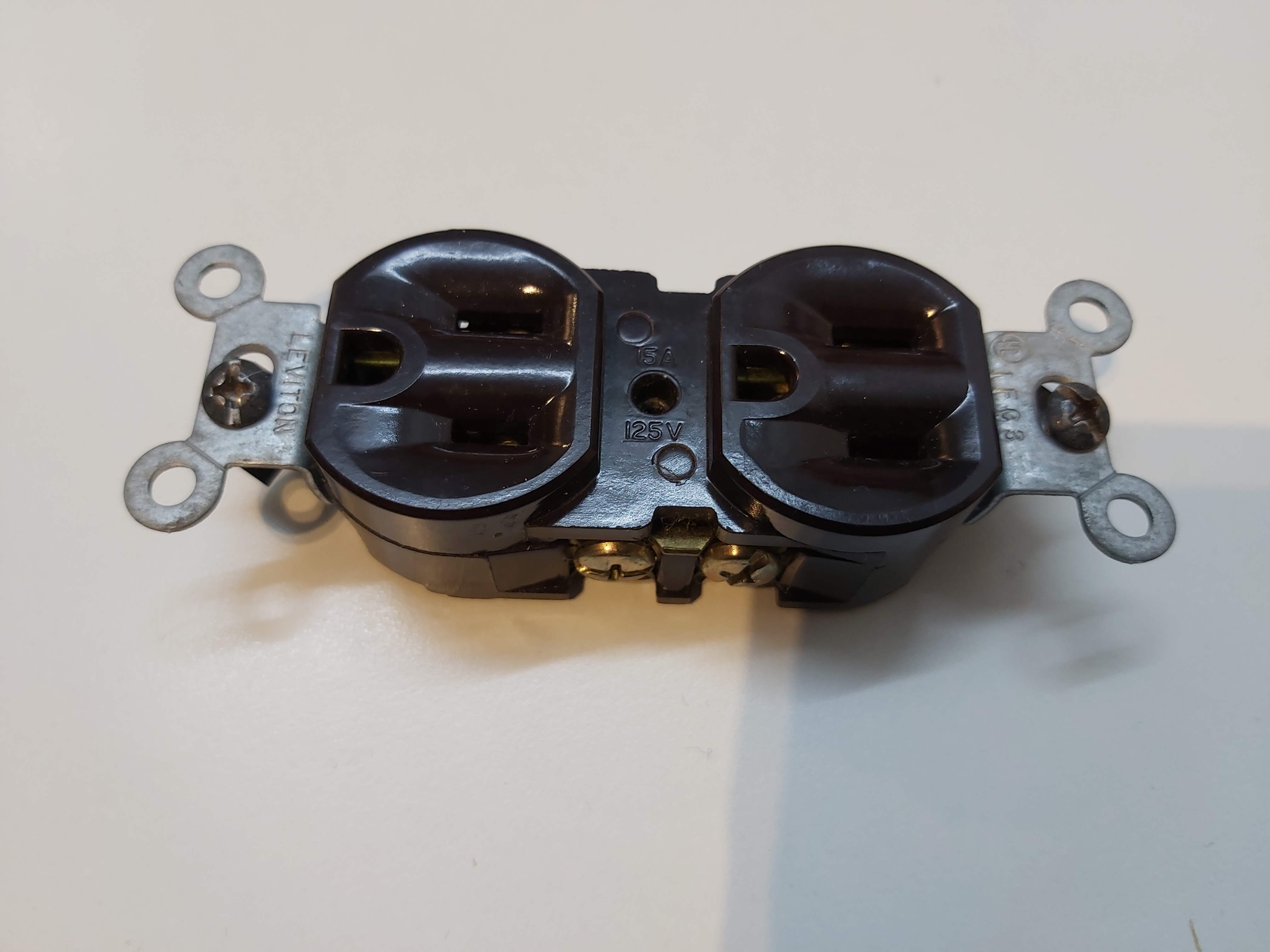
NEMA 5-15 grounded (Type B) plug has two flat parallel blades like NEMA 1-15, and a ground (earth) pin. It is rated 15 A at 125 volts. The National Electrical Contractors Association’s National Electrical Installation Standards (NECA 130-2010) recommends that sockets are mounted with the ground hole up so that a falling object makes first contact with the ground pin. This socket is recommended in IEC standard 60906-2 for 120-volt 60 Hz installations. NEMA 5-15 grounded (Type B) sockets accepts also NEMA 1-15 ungrounded (Type A) plugs. In stage lighting, this connector is sometimes known as PBG for Parallel Blade with Ground, Edison or Hubbell. “Typical” 120v receptacles are protected with 15A breaker. This protects the outlet against overload.
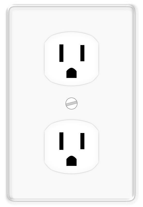
Starting with the 2008 Edition of the NEC (National Electrical Code) the NEC has required tamper-resistant receptacles be used in certain locations. The NEC has been increasing the requirement for receptacles to be tamper-resistant with the revisions after that.
Tamper-resistant receptacles work by having a plastic shutter in front of where the plug gets inserted, which is only moved out of place if objects are placed into both slots of the receptacle TR-rated outlets feature “TR” engraved into the outlet faceplate, typically between the two prongs. The shutters remain closed until the proper plug is inserted. This ensures that items like knives, forks, or loose jewelry are not able to access plugs, thus reducing electrical shock injury.
Nothing is safe. There are only degrees of safety. None of these designs can always prevent a determined or negligent person from electrocuting themselves.
There are some people that think that TR Tamper Resistant Outlets Suck
There are also higher current than 15A outputs in use in USA, but a general-use receptacle cannot be on any circuit larger than 20 amps. The NEMA 5-20 AP variant has blades perpendicular to each other. The receptacle has a T-slot for the neutral blade which accepts either 15 A parallel-blade plugs or 20 A plugs. The NEMA 5-20 AP wall socket can accept both 20A plug and 15A plug.
While normal electrical outlets in USA output 120V AC, that’s not the whole story and the voltage the power distribution to most houses work. The distribution voltage is normally the sum of the two 120V lines that are are at opposite phase (180 degree phase shift) plus neutral wire. But in some cases power can come from two 120V lines that have 120 degrees phase shift (some locations which use certain type of three phase power feed). Learn about the US electrical system in this The US electrical system is not 120V video:
US electrical system uses circuit breakers as wiring and fire protection. Circuit breakers are there to stop the cable in the walls of your house melting and possibly catching fire – circuit breakers and fuses perform the function of stopping a fire (which of course is also very dangerous to life). Standard circuit breakers shut off power when the current is too high, like 10, 15, or 20 amps, but a mere 0.030 amps through a body can cause paralysis of skeletal muscles and stop the human heart.
If you are at new house built according current code, you are likely to have also GFCI or AFCI designed trip before anything bad happens. GFCI can protect in many cases against human touching live wire and ground at the same time. But GFCI does not provide protection in all cases, for example if you have your finger between live and neutral contacts on mains plug. AFCI is designed trip if there is arching on the wiring like bad contact, loose wire or failing insulation on wire. AFCI can detect many problems, but not all.
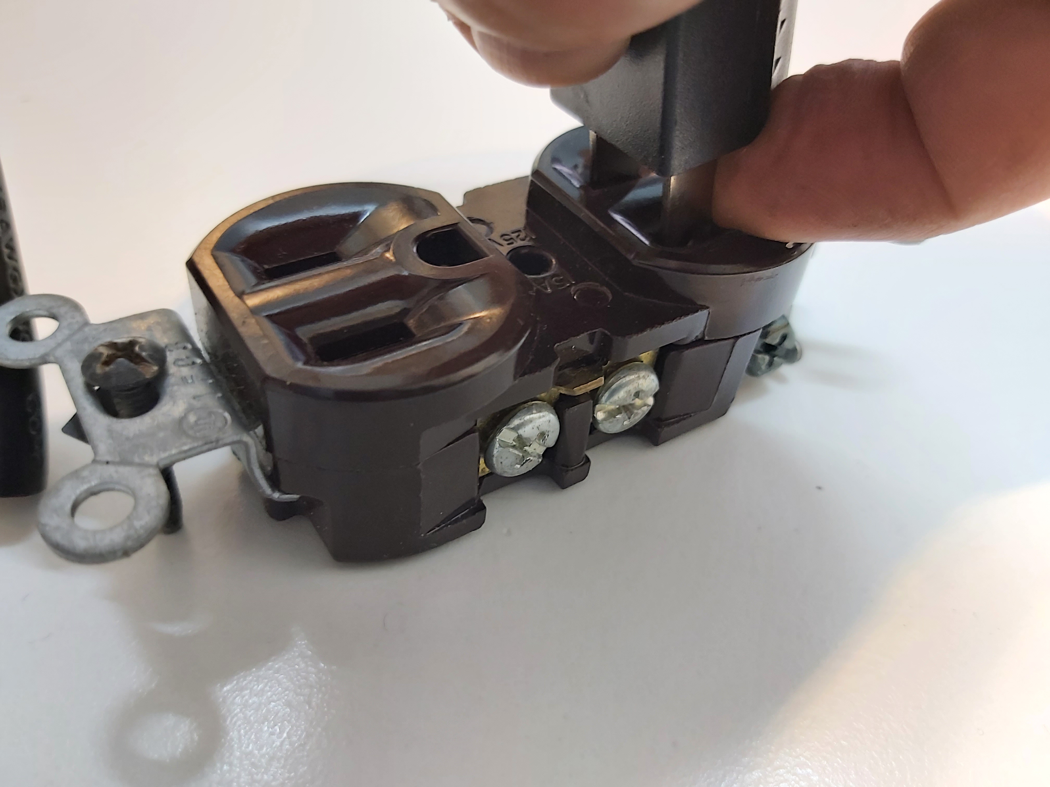
Generally, when things get hot because of overloading, it’s at the connection point and not in the wire. For instance, a lot of electrical fires start at the plug/socket interface either because the connection is poor, there could be corrosion, etc. And sometimes they can happen when nothing is overloaded! This is one of the circumstances in which arc-fault circuit interrupters can save lives.
Overloading an electrical outlet is a common cause of electrical problems. Theoretically the breaker should protect the outlet against overloads, but it does not always do that especially if outlet or wiring is in bad condition. Do not use cords, plugs or outlets that appear damaged, replace them. Always ensure plugs are fully pushed in. Check all outlets to ensure they are cool to the touch, have protective faceplates and are in proper working order. Only grasp plugs by the plug body, keep fingers away from the front edge near the pins and do not pull plugs out by the cords.
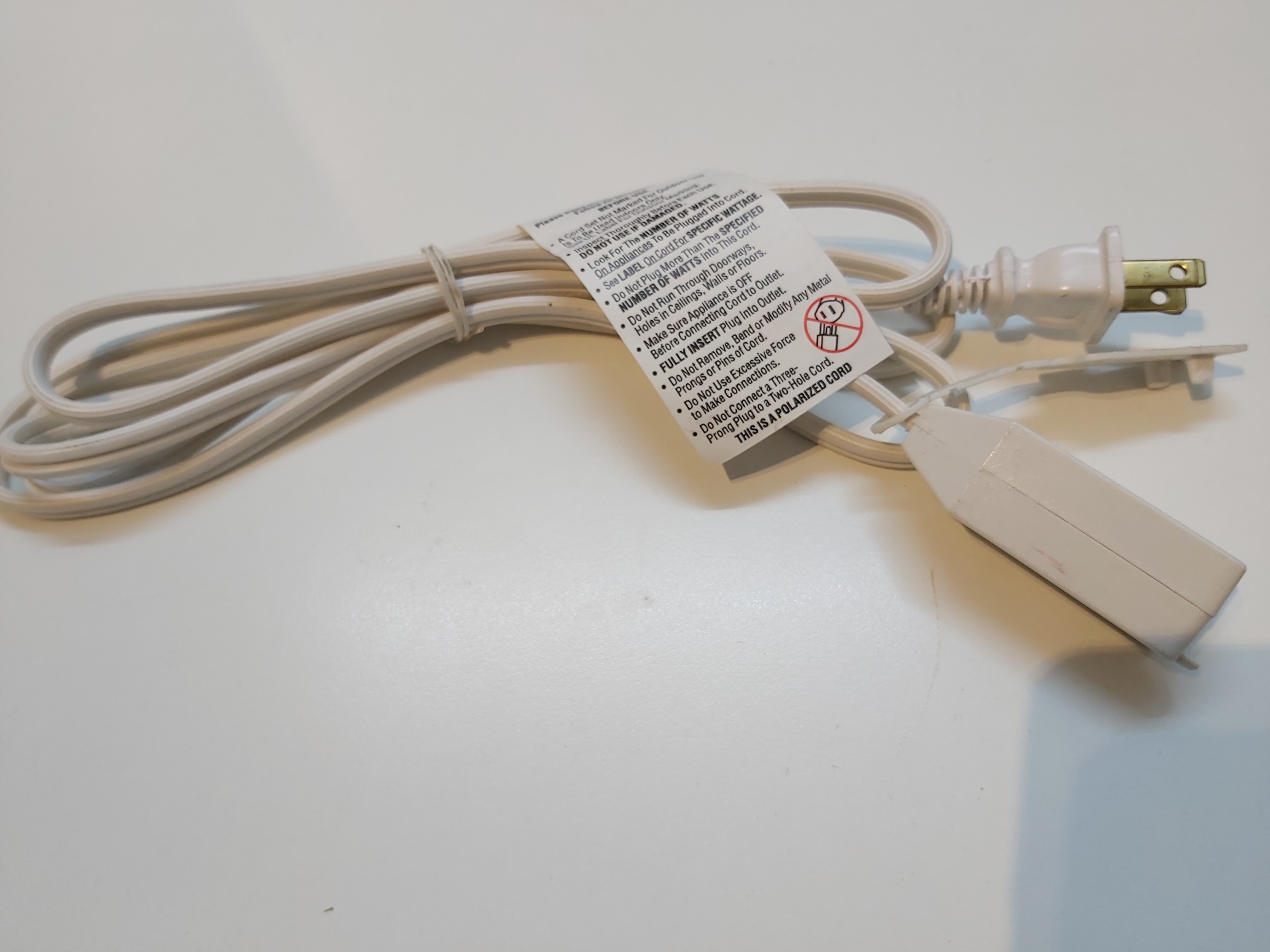
There is a a recommendation that do not use extension cords or multi-outlet converters for appliances, because there are many problems related to US extension cords.
Damaged power cords are a serious residential electrical safety risk, and they are capable of causing both fires and electrocution. All power and extension cords should be checked regularly for signs of fraying and cracking. Power cords should not be stapled into place or run under rugs and furniture.
Besides making sure that the extension cord is in good shape, you need to be really careful that type of extension cord you use in USA. An extension cord essentially is a bundle of insulated electrical wires with a plug on each end. Electrical current flowing through wires generates heat, and when too much current flows through a wire, it can overheat and melt the plastic insulation of the wires, causing short circuits and fires.
Equipment or in-wall wire heating is normally not a problem when you plug an appliance directly into an outlet using its factory cord because the manufacturer has sized the cord appropriately for the electrical current demand of the device. The size of wiring inside wall is rated based on the breaker size on the mains panel (typically 15A or 20A). The size of the wire on the extension cord can be condiderably thinner, and the mains panel breaker might not protect it against overheating due overload. Some better extension cords can have their own overload breaker built-in but not all.
I think allowing unfused 16 gauge (16AWG = 1.5 mm2) extension cords into the market is a potentially bad link in the chain that we could probably do with cutting out. That wire is still pretty OK up to 15A load current, will get warn. If you plug it to 20A outlet and load with 20A total load, it can get dangerously hot (around 1.8 times more power heating the cable at 20A than at 15A). Pulling 20 amps through that cord made it get very hot quite quickly.
In fairness, it used to be much worse. 18 gauge (maybe even 20 gauge) extension cords were available many years ago, but regulators had the sense to make 16 the minimum as time went on.
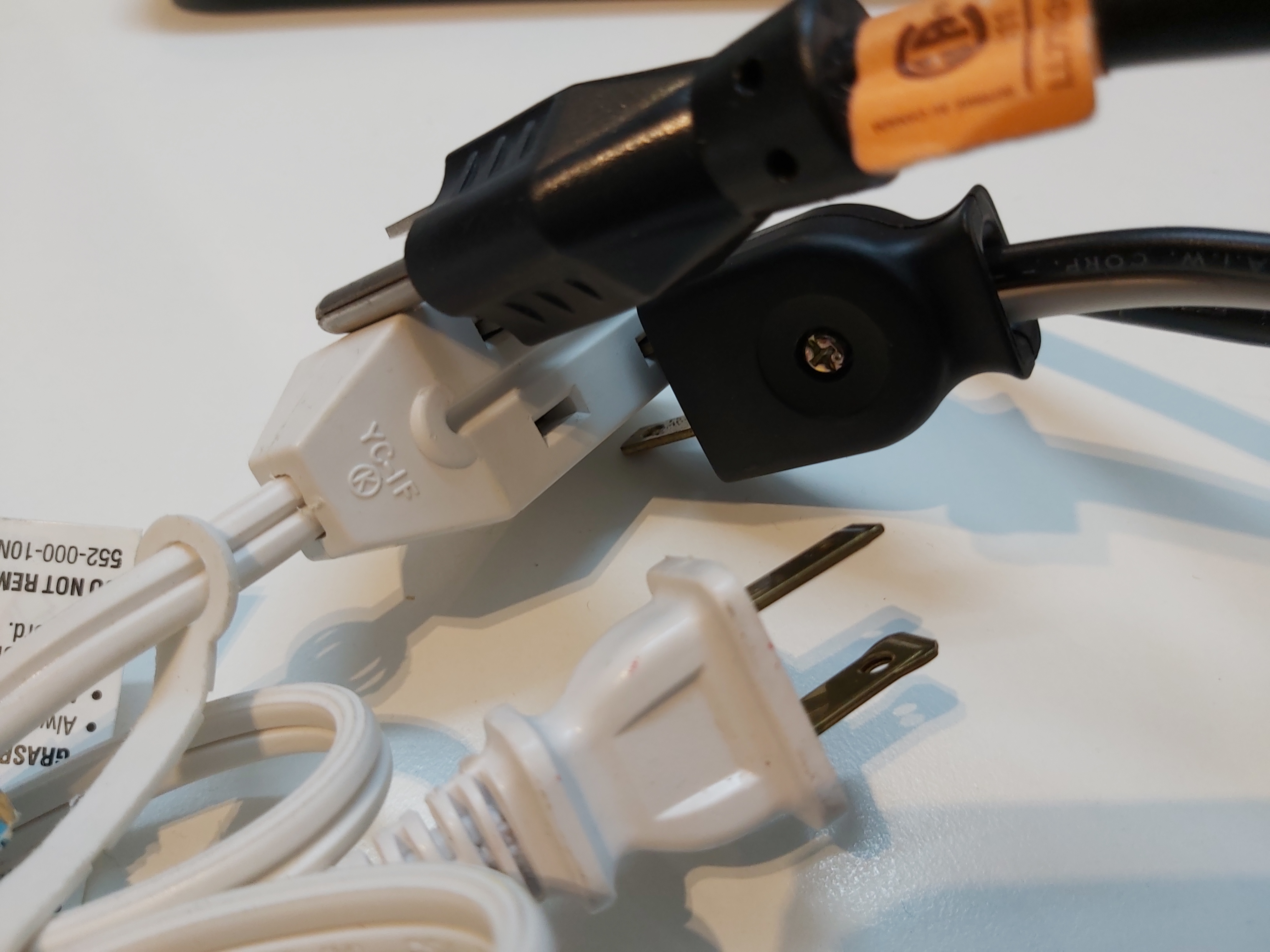
There are also small compact ungrounded extension cords that have such designs whete users can plug in plug so wrongly that they are halfway out leaving the live parts so that the live main voltage can be present on the exposed mains plug pins.
Most electrical fires aren’t the result of a single thing; they’re a cascade of individually not-great circumstances combining to make a bad situation. In order to reduce the risk of fires, we’ve continually been making the not-great things less bad.
294 Comments
Tomi Engdahl7 says:
https://www.powerstream.com/Wire_Size.htm?fbclid=IwAR2I0w2CQ7u-iQUAG6M6mmPDWiGNJo6DNOt-0EL4FkDhMZE3NCHOlVZG9AM
Tomi Engdahl says:
A look at the great transformer shortage affecting U.S. utilities
https://pv-magazine-usa.com/2024/03/07/a-look-at-the-great-transformer-shortage-affecting-u-s-utilities/?fbclid=IwAR2YgFoDyvwiijcX87dy1dpDq63X8NmWPrpPNksdBOD-iN0NzbYgyxVgFzc
An NREL team finds that lead times for transformers has grown fourfold in three years, with orders sometimes taking two years. Additionally price increases of four to nine times have been reported in the past 3 years.
Tomi Engdahl says:
The US plans to invest $1.3 billion in new power transmission lines to protect and reduce strain on the power grid.
https://thebusinessdownload.com/us-to-fund-three-new-power-lines-to-aid-ailing-electric-grid/?fbclid=IwAR1dFXl2xFgfy0vFcxO7Bbz2vzfiw4glwzAorWmwTuDC6i16404pPQq2yWQ
Tomi Engdahl says:
Projects to protect the aging U.S. power grid from extreme weather are getting a big boost in funding.
https://thebusinessdownload.com/us-invests-3-5-billion-to-bolster-power-grid-deploy-clean-energy/?fbclid=IwAR1_w-woNvs3tpaNZc76ymN6wfpDz1SM4P_LzMUS_55T2s1osFwy4Wb1IHE
Tomi Engdahl says:
https://www.electricaltechnology.org/2024/04/light-switches.html
Tomi Engdahl says:
https://www.facebook.com/share/p/tUQXKP39Ri4CDFHX/
This is another step in the wyeification of the Pacific Power service territory around Scio, Oregon.
For our members outside North America, we do things a bit weird around here. Our residential service is single phase with 120/240V split phase. The low voltage means we use many small transformers close to the loads. They’re far more prone to ferroresonance, so most North American utilities have adopted wye primaries. Transformers are always connected in wye, were ferroresonance isn’t a worry.
So when a territory is in delta, they’ll eventually convert it over to wye. Pacific Power had lots of 12kV delta. Sometimes they converted the 12kV delta into 20.8kV wye, or they convert it from 12kV delta to 12.47kV wye. When they go from 12kV to 20.8kV they will re-connect the same transformer in wye; when they go from 12kV to 12.47kV, they’ll put in switchable 6.9/7.2kV transformers in everywhere. They’ll get everything changed out and then bump up the voltage once everything is installed.
The first two pictures were taken in 2018, and this regulator bank was 12kV connected in delta. They had recently added a grounding bank at the substation and were actively installing neutral wires over the territory. I just took the second two today, and the bank has been replaced with a wye connected regulator, running at 6.9kV.
Tomi Engdahl says:
Authorized Personnel Only – How to Start and Sync a 400,000 Watt Turbine Hydroelectric Generator
https://www.youtube.com/watch?v=xGQxSJmadm0
Tomi Engdahl says:
The USA single phase secondary voltage is 120/240 +- 5% residential and +- 10% commercial all at 60 Hz.
3 phase secondary is 120/208 or 277/480 +- 10% 60Hz commercial and industrial.
Some manufacturing plants have 4.5 kv some 34.5 kv 3 phase. That is limited.
Tomi Engdahl says:
The U.S. has not used 110v for over 70 years. 120v is nominal. I have 6 circuits that run 240v split phase. 220v would be a bit more efficient in that it would get rid of one wire, but it’s not a big deal. Make a mistake with 120v and you’re in for a bit of excitement. Make a mistake with 240v (or 220) and you are dead. I don’t mind the tradeoff
Tomi Engdahl says:
Most U.S. sockets are 15 Amps, so “1650W” nominally. 20 Amp sockets are needed for microwaves, etc.
And for induction stoves and electric clothes dryers, etc. there are 240V sockets with decent amperage depending on the age of the house.
Tomi Engdahl says:
Higher voltage means less current means smaller gauge copper wires means less cost. But unfortunately also means more electrocutions of children and dumb people.
Lower voltage means more current means thicker wires means more cost (but less electrocutions), BUT !!! More fires as a result of any loose or corroded connection, especially in wooden houses which are common in USA. High amperage conductors don’t like loose connections very much – they are not good friends!
Tomi Engdahl says:
Why does the meter say 120 but text say 110
it’s just a “ nominal “ label .
Canada folks call it 117V ( the rms part is understood ).
Tomi Engdahl says:
Island County WA, USA, Fire Dept. reminds citizens that plastic-case surge strips are the most frequent cause of the house fires their pumper trucks were called to extinguish.
https://www.facebook.com/share/p/JD73Gic34uHTwFbi/
Tomi Engdahl says:
US plugs have those thin flat pins with the annoying habit of hanging half out of the sockets.
Tomi Engdahl says:
Inside Nordost filter
https://youtu.be/uw9xdTjZPBQ?si=lekfUBqXqTiDc4tO
Tomi Engdahl says:
Electrocuted Birds Are Bursting Into Flames and Starting Wildfires
Power wires normally pose no threat to birds, but that can change if they start trying to find snacks in the wrong places.
https://gizmodo.com/electrocuted-birds-are-bursting-into-flames-and-starting-wildfires-2000495354?fbclid=IwY2xjawFI1p1leHRuA2FlbQIxMQABHR9xHyDYsTjrsCCNP3bT6Qw9GjGxu9dZv5Be9Xe6M60y-eyedmJOS_jenA_aem_QN-jMANZYXsnIgiFHmGmjg
Electrocuted, flaming bird carcasses are falling off of power lines and causing wildfires across the U.S. This surprisingly common phenomenon has been responsible for at least three Colorado wildfires so far this summer
These events are not isolated. A 2022 study found that electrocuted birds caused 44 wildfires in the contiguous United States between 2014 and 2018. That study was led by Taylor Barnes, a biologist who now works for electric utility company EDM International. In the paper, Barnes wrote that “avian-caused ignitions” happen when a bird sits on an overhead power line. For reasons that can vary from case to case, sometimes the bird receives a powerful electrical shock, setting its feathers on fire. The dead or dying bird then falls, and, on occasion, lands in some brush or other flammable material.
“Sometimes they burst into flames,” Barnes told 9News, an NBC affiliate in Colorado. “Sometimes they just fall dead. Not every bird that is electrocuted will fall to the ground and start a fire.”
In the paper, he advised authorities in the area and other fire-prone regions to look into modifying power poles to prevent these electrocutions. Given the devastating effects fires can have and how common they’ve become, it’s surely worth the investment to keep our feathered friends in flight and not on fire.
Tomi Engdahl says:
PG&E shuts power off to thousands in Northern California amid strong winds
About 13,000 customers in Northern California woke up without electricity Friday after Pacific Gas and Electric shut off power to prevent its equipment from sparking wildfires amid dry weather and strong winds expected to last through part of the weekend
https://www.independent.co.uk/news/northern-california-ap-southern-california-san-francisco-pg-e-b2631773.html#Echobox=1729269550
Tomi Engdahl says:
Smart Thermostats Pitched For Texas Homes To Relieve Stressed Grid
https://hackaday.com/2024/11/14/smart-thermostats-pitched-for-texas-homes-to-relieve-stressed-grid/
It’s not much of a secret that Texas’ nearly completely isolated grid is in a bit of a pickle, with generating capacity often being handily outstripped during periods of extreme demand. In a latest bid to fight this problem, smart thermostats are being offered to customers, who will then participate in peak-shaving. The partnership between NRG Energy Inc., Renew Home LLC, and Alphabet Inc. will see about 650,000 of these thermostats distributed to customers.
For customers the incentive would be mostly financial, though the details on the potential cost savings seem scarce. The thermostats would be either a Vivint (an NRG company) or Google Nest branded one, which would be controlled via Google Cloud, allowing for thermostat settings to be changed to reduce the load on the grid. This is expected to save ‘300 MW’ in the first two years, though it’s not clear whether this means ‘continuously’, or intermittent like with a peaker natural gas plant.
AI Thermostats Pitched for Texas Homes to Relieve Stressed Grid
https://finance.yahoo.com/news/ai-thermostats-pitched-texas-homes-210000983.html
(Bloomberg) — Three of the biggest names in US home energy automation are coming together to offer some relief to the beleaguered Texas electrical grid.
Power supplier NRG Energy Inc. is partnering with Renew Home LLC to distribute about 650,000 artificial intelligence-enabled thermostats that use Alphabet Inc.’s Google Cloud technology over the next decade. The initiative, announced Thursday, aims to shave nearly 1 gigawatt of electricity demand — enough to power 200,000 Texas homes or about 1% of the record summer demand seen this year on the state grid.
“The entire industry has been built to serve the peak load on the hottest day of the year,” said Rasesh Patel, president of NRG’s consumer unit. “This allows us to be a lot more smarter about demand in shaving the peak.”
Enrollment in the program, where consumers see cost savings or other incentives for curtailing energy usage, opens in the spring. NRG residential customers will receive service installation of a Vivint doorbell camera and either a Vivint or Google Nest thermostat for free.
NRG expects to sign up enough homes to free up 300 megawatts of electricity demand within the first two years, according to Patel. That is expected to climb to 650 megawatts by 2030, before reaching its 1 gigawatt goal by 2035. Patel said pooling together homes costs $100 per kilowatt — about a tenth the cost of building a typical natural gas-fueled power plant. That would put the program cost at about $100 million.
Google Cloud will be tapped for its AI and machine learning to determine the best time to cool or heat homes, based on a household’s energy usage patterns and ambient temperatures.
Tomi Engdahl says:
https://www.familyhandyman.com/list/things-electricians-never-do-in-their-own-homes/
GEPCO says:
The GEPCO Online Bill service is a convenient way for users to check and pay their electricity bills without any hassle. It saves time and effort by providing an easy-to-use online platform for tracking bills and ensuring timely payments. For more details, visit GEPCO.
GEPCO says:
The GEPCO Online Bill service is a convenient way for users to check and pay their electricity bills without any hassle. It saves time and effort by providing an easy-to-use online platform for tracking bills and ensuring timely payments. For more details, visit GEPCO
Tomi Engdahl says:
Myles McCormick / Financial Times:
The NERC, overseen by the FERC, warns soaring US electricity demand from data centers to power AI could strain US and Canadian grids, risking blackouts — Surging demand from tech sector could overwhelm generation capacity, report says — North America’s electricity grid faces …
https://www.ft.com/content/7c241e6f-e9c1-4f45-883a-8d46e6bf8cd8
Tomi Engdahl says:
AI data centers reportedly cause power problems in residential areas — decreased power quality in homes near data centers causes reduced lifespan for electrical appliances
https://www.tomshardware.com/tech-industry/artificial-intelligence/ai-data-centers-reportedly-cause-power-problems-in-residential-areas-decreased-power-quality-in-homes-near-data-centers-causes-reduced-lifespan-for-electrical-appliances?utm_content=tomsguide&utm_medium=social&utm_campaign=socialflow&utm_source=facebook.com&fbclid=IwZXh0bgNhZW0CMTEAAR0-ZZErVwBI9einUZbQJZkjb59nQe8tBfxEloqTfA6mqzIgiSvFOwh3HII_aem_V1es9SJlNmg25n-rcMl55Q
The average American consumer is starting to pay for the additional power consumed by new data centers.
Reports from around a million residential power quality sensors throughout the contiguous United States show that power quality is declining in areas near massive data centers. The Bloomberg special report shows that the worst distortions often occur within 50 miles of a major data center, affecting nearly 3.7 million Americans. Poor power quality reduces the life span of electrical appliances, which can cause malfunctions, overheating, and electrical fires.
The data behind the report was gathered through Whisker Labs Ting devices, smart sensors that monitor the overall electrical quality in your home and help prevent electrical fires. With over a million devices deployed nationwide, nearly 90% of American homes have a Ting sensor within a half-mile radius. These sensors provide Whisker Labs with granular data, allowing the company to see consumers’ average power quality within their homes in a given area.
“Harmonics are a pretty good canary in the coal mine for early signs of stress and problems,” says Whisker Labs CEO Bob Marshall. Bloomberg likens poor harmonics or power quality to the static you hear from speakers when it’s pushed beyond its limit.
However, the power providers in some of the affected areas are disputing these claims. “ComEd strongly questions the accuracy and underlying assumptions of Whisker Lab’s claims,” Commonwealth Edison spokesperson John Schoen said in an email to Bloomberg. “Ting devices are installed in the home and do not directly measure harmonics on the grid.”
Virginia power provider Dominion Energy also says it hasn’t seen the distortion levels reported by Whisker Labs and claims its measurements stay within industry standards.
Thankfully, Bloomberg says there is an easy solution to this problem, and some solutions are already being worked on. But in the meantime, power companies should look into the data Whisker Labs delivered, especially if they’re widespread. After all, issues appearing in hundreds of homes might be a problem with the electrical infrastructure within those buildings. Still, if the issue affects millions of Americans, it could likely be a symptom of a more widespread grid problem—something that must be addressed before it’s too late.
Tomi Engdahl says:
https://bestrecipes.ma2roc.tech/2024/12/10/important-to-know/
Power strips are a common household item, providing a convenient way to expand the number of outlets available in a room. However, their misuse can lead to dangerous situations, including electrical fires. Firefighters and safety experts emphasize the importance of understanding what should and shouldn’t be plugged into a power strip to prevent accidents and ensure the safety of your home.
Tomi Engdahl says:
Energy giant makes staggering admission about Los Angeles fire: Live updates
https://www.dailymail.co.uk/news/article-14273225/Fresh-fears-LA-Palisades-fire-quickly-spreads-celebrity-neighborhoods-Mandeville-Canyon-Brentwood-405-freeway-partially-shuts-Live-Updates.html
Californians are facing fresh peril over the devastating wildfires as the largest of the blazes continues to spread – with officials now warning that fast and erratic winds may spread the fires throughout untouched areas over the weekend.
The disaster has already claimed the lives of at least 11 people and destroyed more than 10,000 structures.
Amid a search for the cause of the crisis, energy firm Southern California Edison admitted its grid short-circuited just after 10pm on Tuesday when a tower went down – the same time the Hurst Fire erupted.
Energy company’s Hurst Fire admission comes after electrical tracking firm made similar reports
As investigators continue to search for the cause of the Los Angeles fires, new evidence potentially points to downed power lines as a possible source.
Southern California Edison said in a filing on Friday that one of its high-voltage power lines short-circuited at around the same time the Hurst Fire erupted on Tuesday.
Although Edison said it was not yet clear if the fallen power line happened before or after the fire started, it comes after Bob Marshall, the chief executive of Whisker Labs, a company that monitors electrical activity, told Fox News that the firm saw spikes in faults in the hours before the Eaton, Palisades and Hurst Fires.
Marshall said data shows the power was not immediately shut off after the faults surged, and may have been caused by ‘tree limbs touching wires or wires blowing in the wind and touching.’
‘That creates a spark in a fault, and we detect all of those things,’ Marshall said. Faulty electrical equipment, a sudden surge in electrical demand or earthquake tremors are also possible causes of the surges.
Energy company admits power line went down around same time as Hurst Fire
Southern California Edison said in a filing on Friday that one of its high-voltage power lines short-circuited at around the same time the Hurst Fire erupted on Tuesday.
Fallen electrical equipment was found at a transmission tower at the circuit in Eagle Rock/ Sylmar, with the company saying the fault occurred shortly after 10pm, around the same time as the blaze.
Edison saiud it was not yet clear if the fallen power line happened before or after the fire started, and investigations have been launched.
The Hurst Fire was reported at around 70 percent contained on Saturday after it tore through roughly 800 acres.
Tomi Engdahl says:
https://www.electricaltechnology.org/2025/01/wire-nuts-connectors-color-codes-wire-gauge-sizes.html#google_vignette
Tomi Engdahl says:
Power line had increase in current on day of Eaton Fire, California utility says
Southern California Edison told the state that a fault was detected several miles from where the fire is believed to have .
https://www.nbcnews.com/weather/wildfires/power-line-increase-current-day-eaton-fire-california-utility-says-rcna189564
Tomi Engdahl says:
https://www.edn.com/ground-fault-interruption-protection-without-a-ground/
GSC Infra solutions says:
Electrical power in the U.S. can be risky if not handled right. From downed power lines to overloaded circuits, it’s crucial to stay aware of potential hazards. Always follow safety tips to keep yourself and others safe from unexpected shocks or fires.
if anyone wants to know more about Copper Bonded Earthing Electrodes should contact gscearthing.com
GSC Infra solutions says:
Power safety is no joke! It’s crazy how much we rely on electricity, but there are real dangers lurking, from overloaded circuits to improper grounding. Staying informed and taking precautions is key to avoiding accidents. Definitely something we all need to be mindful off. if anyone wants to know more about Copper Bonded Earthing Rod should contact gscearthing.com
Tomi Engdahl says:
https://www.ecmweb.com/safety/arc-flash/article/20898038/the-case-of-the-deadly-arc-flash?fbclid=IwY2xjawIbtjVleHRuA2FlbQIxMQABHSiSibLU9NR35lU_t9G-7p-WGkzEZ07LO2BrBn3S4TIPKjgZ2YYVn5k_3Q_aem_o_vYDPd0JnE3ciSB–m9wQ
Tomi Engdahl says:
Smoking distribution board
https://vm.tiktok.com/ZNdeheLwQ/
somaya solar solutions says:
US electrical power systems face some serious risks – from aging infrastructure to natural disasters. Power outages can disrupt daily life, and grid vulnerabilities make it easier for hackers to cause chaos. We need upgrades to keep things running smoothly and safely. if anyone more information about Domestic Solar Panel.
Tomi Engdahl says:
Why are US Homes Wired Using Solid Wire rather than Stranded Wire?
https://www.electricaltechnology.org/2021/11/solid-wire-rather-than-stranded-wire-us-wiring.html
Tomi Engdahl says:
We DO use 240V, where it’s needed. A lamp isn’t going to make a huge difference whether it’s at either voltage so the lower 120V equates to better passive safety when the entire circuit and all its failure modes are considered. Our ovens, water heaters, resistive heat, and other major appliances overwhelmingly use 240V.
Our residential power is delivered as split-phase. There are two hots that are each 120V nominal and 180 degrees out of phase, allowing for phase-neutral at 120V or phase-phase at 240V, anywhere in the house. This is accomplished simply by using a center-tapped transformer where the 13kV steps down for final delivery to a group of houses. The neutral is the center tap, and it’s bonded to an earth rod at the main panel of each house.
Thus, more choice, more power to the people, Rah Rah ‘Murica.
Tomi Engdahl says:
Why Does the USA Use 120V While Most of the World Uses 230V?
https://www.electricaltechnology.org/2023/03/standard-voltage-120v-240v-us-230v-eu.html
Tomi Engdahl says:
https://www.edn.com/can-a-household-manage-on-just-50-amps/#google_vignette
Tomi Engdahl says:
Buyer Beware: Cheap Power Strips Hold Hidden Horrors
https://hackaday.com/2025/04/07/buyer-beware-cheap-power-strips-hold-hidden-horrors/
https://www.youtube.com/watch?v=z8YdOG9biKU
Tomi Engdahl says:
The problems with FPE panels are inherent in the design of the split bus. The two halves were easily overloaded. Since the top half doesn’t have a main and has (6)2P breakers and one of which was the main for bottom half; which was fed via a 2p/60.
The top (5) 2P breakers were not protected by a main, therefore could be easily overloaded.
It wasn’t that the breakers were known for not tripping. It’s because you could basically install much higher amperage breakers than the top half buss was designed for. Hence why the top half of the panels would often overheat and cause fire damage.
John Hall no, that is called a split buss panel. All brands made those panels and that was not the problem. The problems with federal panels was numerous……the buss design as in the way the breakers plugged in, and of course the breakers not tripping durring a short circuit or major fault. They would jam and hold closed, especially 2 pole breakers. On simple overloads they tripped fine, but on a short they would hold. Then the UL saga where they obtained the UL label under false pretenses and thats what landed them in hot water and losing the UL designation in 1986. They then went out of business and soon after Scnider (square d) bought them.
John Hall i took an fpe 30 amp breaker in an open panel and tied it to the neutral with a #6 about 18″ long turned it on and watched it melt for a good 30 seconds before we shut off the the fireworks show. So I would have to disagree that point on the breakers not tripping.
Ok national electric code is for new installs to keep up with new laws inplace for new systems the only time you should upgrade too new codes is in failure of older system pole fell down breaker box got ripped out by riser etc so yes he is pumping you for expense you don’t need
This is why you call professional not your buddies on Facebook cause people have no education on this stuff and can cause your house to catch fire because of this is panel. As an electrician I beg you to change this panel for your safety
They nicknamed them arc welders for a reason. I’ve got one to change out very soon and also when I was a kid my grandpas garage had one and the main didn’t trip when it should have. Panel was glowing lol luckily they caught it right before quitting time
Federal Pacific are dangerous and unlikely to react to a fault
federal Fire starter
Most insurance companies want those panels replaced otherwise they will cancel your insurance
The FPE boxes are known to be fire hazards. If you do have a fire and it’s traced back to the panel, your insurance company may use it as a reason to not pay any claims. Don’t gamble with your pocketbook or someone’s life. Replace it…
The problem I found with Federal Pacific panels the breaker will trip, but electricity will still run through the breaker a real shock and fire hazard.
I work for an insurance company and we won’t accept these – major fire hazard you should replace
These panels are banned and an extreme fire hazard. I’m taught at my work that we don’t even take the panel cover off u til power is off and we are replacing the panel
FPE=Fire Placed Everywhere
Time to replace the box. They Federal Pacific lost their URL listing in 1980
It’s all BS, I have been in the business for close to 50 years and have NEVER had an issue with an FPE panel…. Take a look at a Challenger panel they are not listed and I have had so many issues with those really bad breakers…. same with Zinsco…. The worse thing with them is the last. guy that worked on them, you have to make sure they fit the bus tight. Missed by every guy that works on them?????? After years and years you see how rookie electricians or DUY guys make things worse…..
Federal Pacific, pushmatic, and zensco brand panels and breakers are uninsurable in most condo apartment complexes in Michigan
Needs to meet code at the time of construction and inspection for a certificate of occupancy for the electric company to connect power. Old work does not need to be brought up to current code, but the new work does have to meet code.
No the gray paint on entrance boxes & junction boxes is no çonductive medal paint, when you paint it any time it against the NATIONAL ELETRICAL CODE, TO DO,HAS BE REPLACEMENT. SORRY
We called FPE breakers no-blow breakers.
they lost their UL listing due to almost a 30%breaker fail rate. They fail in 2 ways, 1 is they won’t trip when overloaded, and they have a mounting fail point.
Many insurance companies will require replacement if they find out this panel is in the building. If you refuse, they will drop your coverage. Same with Zinsco panels.
FPE panels are actually well constructed panels. The breakers used to be made in China and when they were they weren’t tripping, but now they are made by Connecticut Electric so back in America so that’s good. Now that said, these breakers are only thermal. So if you close a breaker into a fault it will hum a couple seconds before they trip. Newer breakers have a magnetic element that will trip it out immediately in the case of a short circuit. It’s not a bad thing to change it out, the breakers are very expensive and eventually will be hard to find, but you don’t have to rush changing it. Change it when you can afford to. I think most companies charge about $1500 for a sub panel replacement
If it complied with the code and was accepted by the inspector AT THE TIME IT WAS BUILT, it is presumed to be in compliance now. Imagine the mess you would create if every time a new code was written, all aspects of all buildings would have to be upgraded to meet the new codes. That would be an EX POST FACTO law, and is unconstitutional!
Federal Pacific panels are notorious for having major arcing due to the bus bars breaking down due to electrolysis
https://www.facebook.com/share/p/1BxGLvdGpA/
Tomi Engdahl says:
Why is Solid wire used in the U.S for home wiring while stranded wire is used in the rest of the world?
https://www.electricaltechnology.org/2021/11/solid-wire-rather-than-stranded-wire-us-wiring.html
Tomi Engdahl says:
Homes are wired with solid wire instead of stranded wire mainly for the following reasons:
1. Cost: Solid wire is cheaper to manufacture than stranded wire, making it more economical for large-scale residential wiring.
2. Ease of Termination: Solid wire is easier to insert into outlets, switches, and screw terminals. It holds its shape and fits snugly into connectors, making for more secure and consistent connections.
3. Durability in Walls: Once installed, solid wire is less prone to damage or flexing. It stays put, which is ideal for permanent, behind-the-wall installations where flexibility isn’t needed.
4. Lower Electrical Resistance: Solid wire has slightly lower resistance than stranded wire of the same gauge, which can improve efficiency over long runs—important in house wiring.
Stranded wire is typically used where flexibility is needed—like in appliances, vehicles, or extension cords—not inside walls.
Tomi Engdahl says:
germany also use solid wire for instalation cable, , stranded only für portable and devices
Tomi Engdahl says:
Not compatible with Federal Pacific or Zinsco breakers
That’s a breaker tester. If the breaker fails, this melts in your hand.