I bought a Lutron LCR-9063 meter long time ago (expect around 20 years or more) to be able to measure value of coils and capacitors. I has worked well for me. What looks like the same meter are sold as VOLTCRAFT LCR-9063 Component tester.
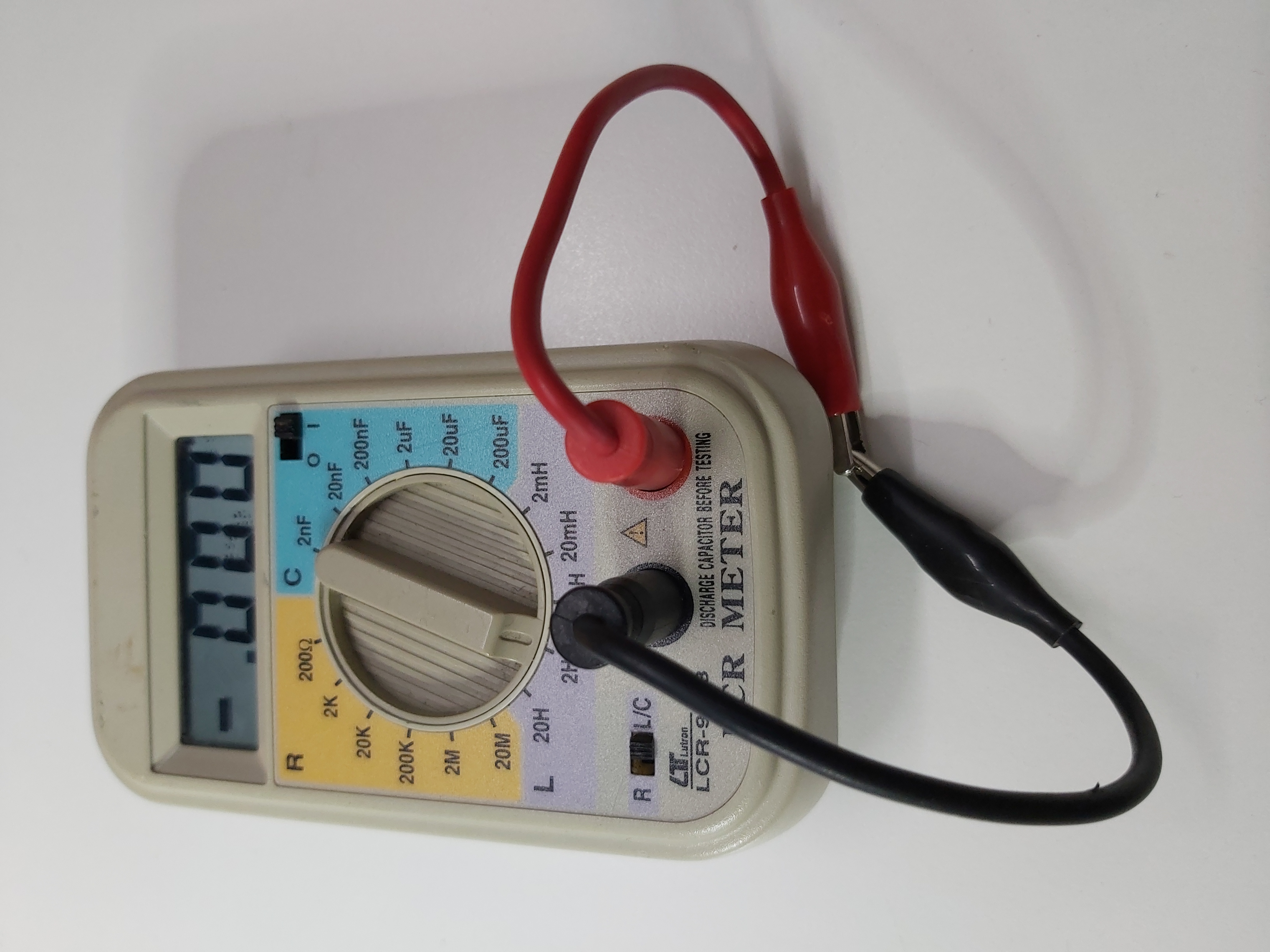
This meter is designed for measuring resistance, inductance and capacitance. LCR-9063 enables to make measurements of no-load components, such as resistances in the range 0 to 20MΩ, capacitors in the range from a few pF up to 200μF, and inductors in the range from a few μH up to 20H. It is aimed to be used hobby electricians, hobbyists and electronics developers.
Some meter data:
Display: 2000 counts
Sampling Time Approx. 0.4 second.
Reading range – resistance: 0.1 Ω – 20 megaohms
Reading range – capacity: 1 pF – 200µF
Reading range – inductance: 2 mH – 20 H
Measurement frequency for L and C: 250Hz
Some documents worth to check out:
- User manual at https://www.manualslib.com/manual/841317/Lutron-Electronics-Lcr-9063.html
- Service manual at https://www.mikrocontroller.net/attachment/202219/Lutron_LCR-9063.pdf
- Radiomuseum has page on meter that looks same Voltcraft LCR Meter LCR-9063 with inside pictures
- Funktionsweise Lutron\Voltcraft LCR-9063
Next question is how this meter works.
The service manual contains this circuit diagram of the device:
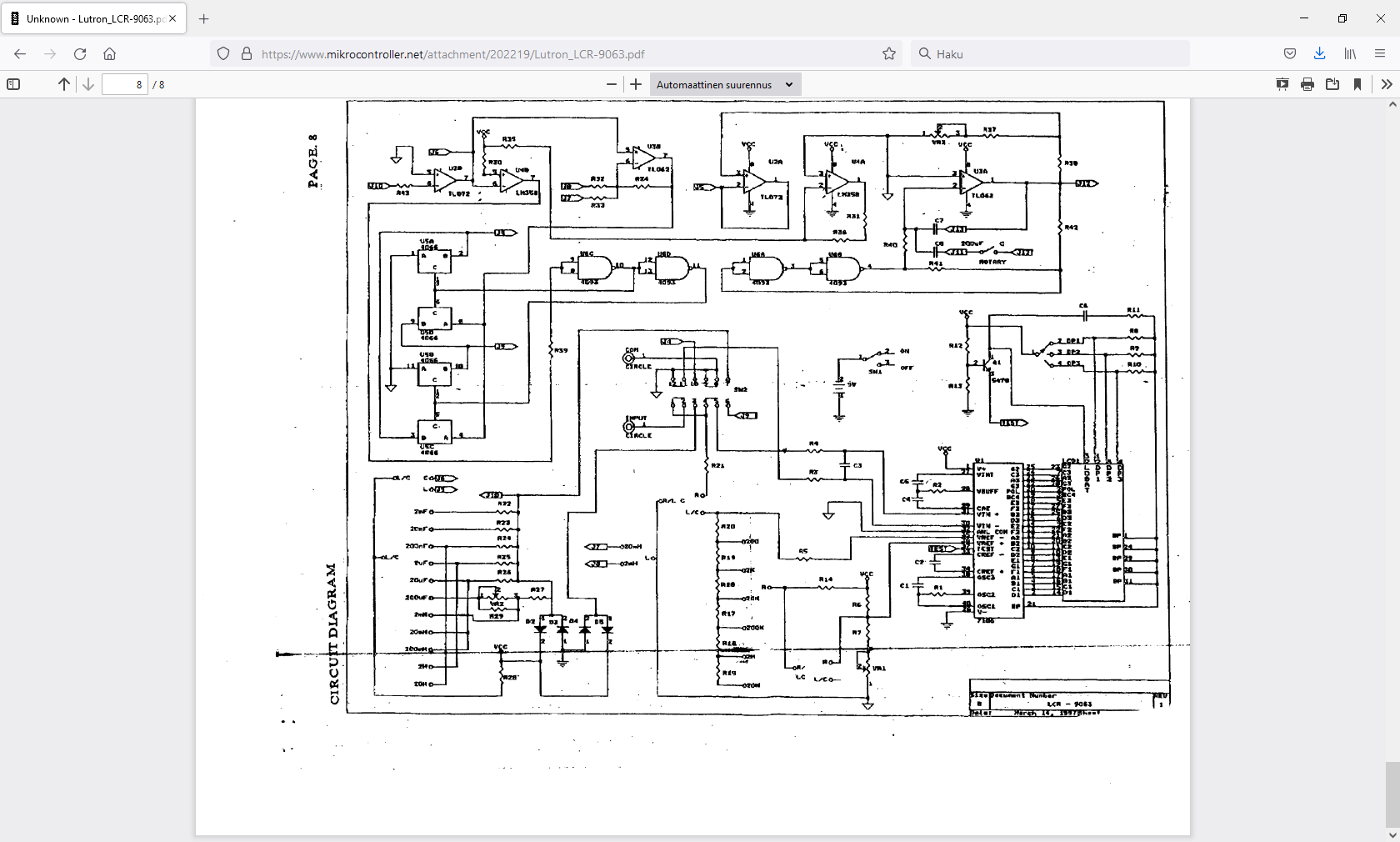
The measurement circuit is based on 7106 multimeter measurement IC (like cheap DT830 multimeters). Resistance measuring seems to be quite similar to resistance range on normal multimeter. The resistance measuring uses 600 mV / 300 mV voltage according to meter documentation.
To be able to measure inductance and resistance, this meter has a 250 Hz AC signal generator. The idea is that L and C are measured with this AC signal going through them instead of DC.
The capacitance measurement tries to keep a constant amplitude AC signal (few hundred mV triangle wave when capacitor is in place) over the capacitor. The AC voltage causes a predefined current pass the capacitor (depends on capacitor value how much) and that current is measured (current directly proportional to capacitance value).
The inductance measurement applies a square wave AC signal to to coil being measured. This AC square wave has amplitude of around two volts when there is no inductor in place, and drops to few millivolts or tens of millivolts when there is a inductor in place. It seems that the voltage over the inductor is directly proportional to inductance of the coil. On my tests I could get strange inductance readings when I connected a capacitor or resistor in place inductor being measured (lower resistance value or bigger capacitance value showed lower false inductance reading).
2 Comments
Tomi Engdahl says:
http://www.troelsgravesen.dk/Low-DCR-coils.htm
Tomi Engdahl says:
3 Ways to Check Capacitors in Circuit with Meters & Testers
https://www.youtube.com/watch?v=qDABYKoVO4Q
Learn How to check bad Capacitors in circuit boards with ESR and Fluke multimeter, ESR meter reading is ohms and Fluke capacitor reads microfarads uf mf of a cap, see below for “capacitor meters”
Fluke multimeter 115 – http://amzn.to/2hIgCub
MESR-100 V2 Auto Ranging in-Circuit ESR METER- http://amzn.to/2hRgTyl