This post is about European mains power. Electricity in EU countries conforms to the European standard, coming out of the wall socket at 230 volts alternating at 50 cycles per second. While the voltage and frequency are fixed, the mains connectors and wiring practices can vary between different countries in Europe.
One thing to note on European power outlets is this: In most European countries mains outlets are not polarized, and you can put the plug in both ways, so you almost never know which wire is live and which is neutral. Typically, Europeans do not maintain consistent identification of line and neutral throughout their power system as is the practice in North America. Consistent with this practice, the Continental European plug can be rotated to either of two positions and plugged into the socket. Thus, the common electrical system in Europe is unpolarized (i.e., line and neutral are connected at random). In fact, most plug types used in Europe are not polarized. The ungrounded plugs have been non polarized, grounded outlets are either polarized or non polarized depending on country.
History of European 230V power
Europe’s power grid, the world’s most interconnected, is set at 230 volts (an EU standard since 2008). Before that the voltage standard had been 220V (most countries) or 240V (UK and Ireland).
It was the Germans who introduced 220V AC power in Europe over 100 years ago. It was around 1893 when the AC frequencies were standardized at 60Hz (US) and 50Hz (Europe). At that time there were some systems that used 120V and also 220V systems. Europe had developed its 220-volt (now 230-volt) system after learning from the American experience, and before any massive infrastructure changes would be required. Cost was the main reason Europe went with 220 volts (now 230): higher voltages allow the use of thinner wire, meaning less copper in the early days of power lines. Power companies could save money on wire by using 220 volts rather than 110. This became the model for electrical distribution in Germany and the rest of Europe and the 220-volt system (later 230-volt) soon became the European norm.
Single phase power in Europe The nominal European voltage is now 230V 50 Hz (formerly 240V in UK, 220V in the rest of Europe). European mains voltage is presently specified as being 230 V+10%/−6% (253-217V) specification will broaden to 230 V±10%, requiring electrical goods to operate correctly on a supply anywhere between 207 and 253 V. The “harmonised voltage limits” in Europe are now: 230V -10% +6% (i.e. 207.0 – 243.8V) in most of Europe (the former 220V nominal countries) 230V -6% +10% (i.e. 216.2 – 253.0V) in UK (former 240V nominal) his is really a fudge and means there is no real change of supply voltage, only a change in the “label”, with no incentive for electricity supply companies to actually change the supply voltage. To cope with both sets of limits an equipment will therefore need to cover 230V +/-10% i.e. 207-253V.
Outlet wiring
Modern European 230V (50Hz) supply feeding the mains outlet consists of 3 wires that are typically: hot, neutral, and safety ground. The 230V (50Hz) is obtained between the hot and neutral lead. The current available from the outlet depends on the maximum current rating of the breaker in mains panel that is normally 10A or 16A (in UK there are maximum 13A fuse inside mains plug). Older building can have older outlets that do not offer grounding on “safe” locations (normal rooms) and grounded outlets on “dangerous” locations (like outdoors, washing room, kitchen).
There modern colors used in house wiring in Europe are based on IEC standard: GREEN with YELLOW stripes is Ground, BLUE is Neutral, and BROWN is Live. The typical wire thickness (for live, neutral and ground) is either 1.5 mm2 (for 10A circuits) and 2.5 mm2 (for 16A circuits). The extension cords typically are built using 1.5 mm2 cable. The cables feeding equipment are typically use 1.5 mm2, 1 mm2 or 0.75 mm2 wires depending on the power equipment uses.
There is not usually hard guarantees which hole on the outlet is neutral and with is live. The hot and neutral wires are interchangeable as far as the equipment is concerned (be warned that there are some exceptions in some countries). Both are power carrying wires. In many parts of Europe (nordic counties, Germany etc), the normal 3-wire receptacle is symmetrical so that the neutral and hot wire connections can be swapped by simply rotating the plug.
There is not even guarantees that one of the side is neutral, because it is possible that in some locations both the mains outlet power carrying contacts can be “live” with 230V between them. On some countries (for example some locations in Norway and some old installations on some other countries) both current carrying wires on outlet can be “live”. In hospitals the mains outlet designed to be used for medical equipment could be powered from safety isolation transformer, so neither side is “neutral”.
In most parts of Europe the mains wiring is is wired as radial system, which means that there is a straight wire that comes from the mains panel to the fixed load or mains outlet. There can be one or more than one outlet connected to the same wire. That wiring is protected with with a breaker or fuse (typically rated for 10A or 16A depending on how much current is needed and how thick wires are installed). In modern installations there is normally a 10A or 16A breaker on the mains panel that disconnects the live wire when there is short circuit or overload and neutral side is not protects. In addition in modern installations there is usually also a ground fault protector that protects one outlet or a group of outlets. In locations where both sides of mains outlet are live, two pole breakers are used (disconnect both wires going to outlet if there is overload or short circuit). UK is a special case because there residential installations use Ring circuit wiring where the mains plugs have a built-in fuse.
Mains plugs
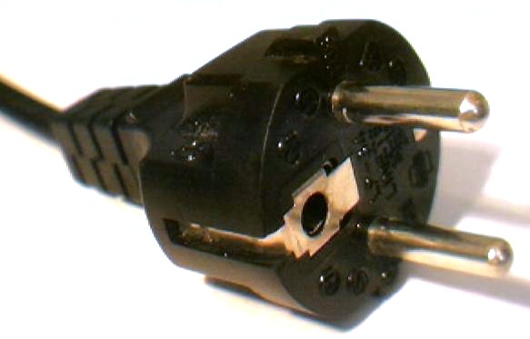
The standard, Class I grounded mains, plugs used in Germany, Austria, the Netherlands, Sweden, Norway, Finland, and Russia are the CEE 7/4 and CEE 7/7 plugs. Because this standard is used so commonly throughout Europe, we refer to it as the “Continental European” standard. Both styles have two 4.8mm round contacts on 19mm centers. s the “Continental European” standard. Both styles have two 4.8mm round contacts on 19mm centers. Grounding is achieved through the grounding clips on the sides of the plug body.
SCHUKO plug
German (type F, CEE 7/3 socket, CEE 7/4 plug, Schuko) is the most common mains power socket in Europe. The most common socket in Europe is the Schuko (Schutzkontakt is German for ‘Protective contact’). The plug has two pins, and along with the socket can be identified by the two metal earth contacts on each side. Schuko is a standard used primarily in Germany and Austria, Finland, Sweden, Norway and several other countries.
The SCHUKO is rated at 230v 16A, and has two 4.8mm x 19mm pins. The metal contacts at top and bottom of the outlet are the “Schutzkontakte”, i.e. earth. Because the plug is symmetrical, there is no way to know which line is hot and which is neutral for a device. Only earth is always the same.
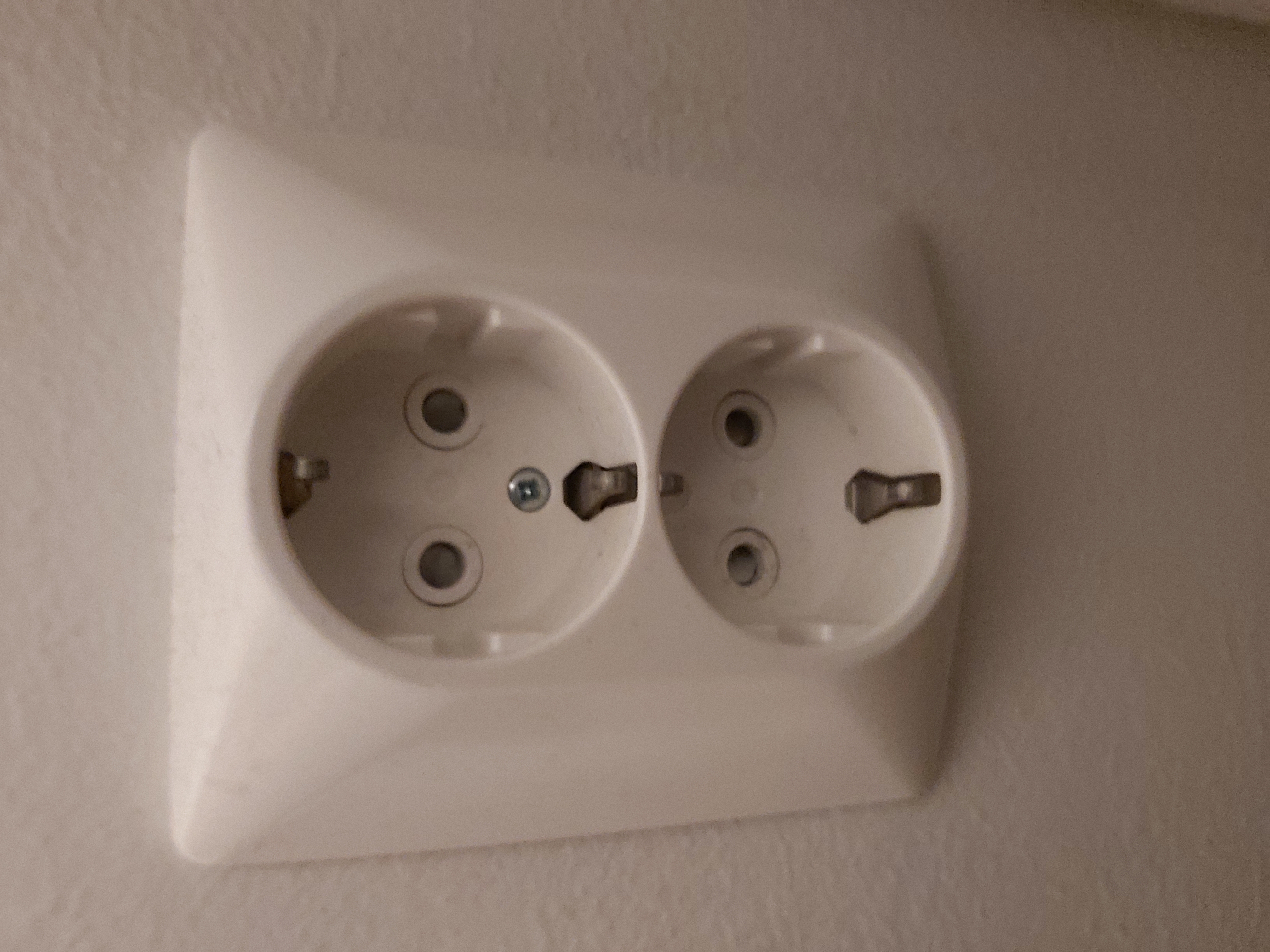
A typical SCHUKO outlet has three electrical connections, which are the “hot”, “neutral”, and “grounding” wires. The hot and neutral wires are interchangeable as far as the equipment is concerned. The normal SCHUKO 3-wire receptacle is symmetrical so that the neutral and hot wire connections can be swapped by simply rotating the plug. SCHUKO plug can be connected either way around, and there is no strong convention as to whether sockets have the live wired to the left or right side of the receptacle.
The Schuko system originated in Germany. It is believed to date from 1925 and is attributed to Albert Büttner, a Bavarian manufacturer of electrical accessories At this time Germany used a 220 V centre tap giving 127 V from current pins to earth, which meant that fuse links were required in both sides of the appliance and double pole switches. Variations of the original Schuko plug are used today in more than 40 countries, including most of Continental Europe.
Why it is not important where we connect our hot and neutral wire when connecting them to our Schuko plug? Is it because current flows in both directions and equipment are designed to cope it. This inherently stupid sounding power plug design from 1925 that is safe enough when certain limitations are met. While obviously not ideal, this symmetry is not a big problem so long as all appliances are built in such a way as to be still safe when the two main wires are swapped. As almost everything is being produced for a global market today, in practice this is always the case – or at least manufacturers always claim and usually provide it. It is UTTERLY ESSENTIAL that anything it is used with may be safely used with phase and neutral in either of the two possible arrangements.
The SCHUKO connector is pretty safe design. Overall though, there aren’t millions of people being electrocuted by Schuko. In fact, it’s generally one of the lowest risks out there because the plug is pretty well designed to be be safe. SCHUKO plug used in some of the most conservative and safety conscious regulatory environments, such as the Nordic region. So, it’s hardly a major risk or concern.
When you insert SCHUKO plug into the socket, the earth connector makes contact first and then the live prongs. By the time an electrical connection is made, there is almost no gap left between the socket and the plug, no room for an inquisitive toddler to put his fingers or other conductive objects. There are also safety shuttered outlets, where the shutters on SCHUKO sockets have to be pressed simultaneously in order to push them aside. Pushing only one will not make it slide away.
Schuko plugs are required for devices with metal cases, the case needs to be connected to earth ground in several places, so any electrical fault would connect line to earth or neutral to earth. SCHUKO sockets also accept non-grounded EURO plugs that are used on “dual insulated” equipment that are designed to be safe to be operated without ground.

SCHUKO design is very safe for users to use. When inserted into the socket, the Schuko plug covers the socket cavity (1) and establishes protective-earth connection through the earth clips (2) before the line and neutral pins (3) establish contact, thereby preventing users from touching connected pins. A pair of non-conductive guiding notches (4) on the left and right side provides extra stability, enabling the safe use of large and heavy plugs (e.g. with built-in transformers or timers).
Some countries, including Portugal, Finland, Denmark, Norway and Sweden, require child-proof socket shutters; the German DIN 49440-1:2006-01 standard does not have this requirement.
FRANCE plug
The second most common socket is the French type, which like the Schuko is rated at 230v 16A, and has two 4.8mm x 19mm pins. France, Belgium, the Czech Republic, Slovakia and Poland use the CEE 7/6 plug and CEE 7/5 socket with the same size and spacing of the main pins as SCHUKO but with a male protective-earth pin on the socket instead of the earth clips, and without the guiding notches at the sides. The earth connection is made by an earth pin which protrudes from the socket, and engages with a hole in the plug.
The protruding earth pin means that the plug can only be inserted one way around, but the major issue is that until 2002, there was no convention as to whether sockets had the live wired to the left or right receptacle You therefore have a 50:50 chance of it being wired “the correct way” and unlike with the Schuko socket, you cannot rotate the plug 180 degrees.

In order to bridge the differences between German and French standards, the CEE 7/7 plug was developed. It has a hole to accept the earth pin on a French socket, and side strips to connect to the earth clips on the side of German sockets. Most modern moulded Schuko plugs, and good-quality rewirable replacements, are a hybrid version (“CEE 7/7″) with an aperture that accommodates the earth pin of CEE 7/5 sockets.
Other outlet types
Denmark and Greenland use their own 16A socket. The socket looks quite similar to a Schuko/French socket, but the grounding is different than in those (third pin on socket). Denmark also supports using French sockets and Schuko sockets.
Historically Italy has had its own specific three pin plug and socket, available in 10A and 16A versions. Many modern sockets will accept both 10A and 16A plugs. Many buildings now have the Bipasso/Schuko socket, which can be used with both Italian and Schuko plugs. Also Switzerland and Liechtenstein use their own specific three socket, available in 10A and 16A versions. Britain has it’s own set of mains outlets that are different from ones used in continental Europe.
Europlug
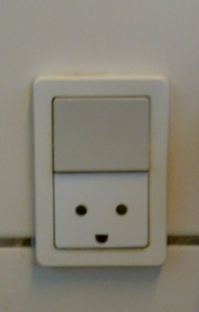
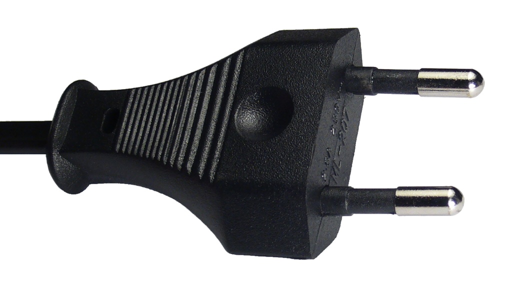
The Europlug is a flat, two-pole, round-pin domestic AC power plug, rated for voltages up to 250 V and currents up to 2.5 A. It is a compromise design intended to connect low-power Class II appliances safely to the many different forms of round-pin domestic power socket used across Europe. It is compatible with SCHUKO, France type outlet and several other outlet types in use in Europe (except UK outlets).
The Europlug design, intended for use with socket-outlets meeting other standards, appeared first in 1963 as Alternative II of Standard Sheet XVI in the second edition of CEE Publication 7 by the contributing members. The Europlug is therefore sometimes also referred to as the “CEE 7/16 Alternative II plug” or simply as the “CEE 7/16 plug”.
It is a small size plug that allows compact power cables and mobile phone changers. Europlugs are only designed for low-power (less than 2.5 A) Class II (double-insulated) devices that operate at normal room temperature and do not require a protective-earth connection. The Europlug is designed to be compatible with mains socket types C, E, F, and K (all have 4.8 mm holes with centres spaced 19 mm apart).The Europlug is not designed to be compatible with mains sockets used in UK.
The dimensions of the Europlug were chosen for compatibility and safe use, such that with continental European domestic power sockets. The plug is designed so that a reliable contact is established when the plug is fully inserted and no live conductive parts are accessible while the plug is inserted into each type of socket: it is not possible to establish a connection between one pin and a live socket contact while the other pin is accessible.
Europlugs are designed to be non-rewirable and must be supplied attached to a power cord. Europlugs are designed to be used with ‘double-insulated’ or ‘all-insulated’ apparatus is made which does not require earthing. Double insulation means what its name says, and all live conductors are separated from the outside world by two separate and distinctive layers of insulation. Each layer of insulation would adequately insulate the conductor on its own, but together they virtually negate the probability of danger arising from insulation failure. Typically the double insulated devices are built into insulating plastic case, but in some case also metal case is possible (for example on amplifiers, CD/DVD players and VCRs). Double insulation avoids the requirement for any external metalwork of the equipment to be protected by an earth conductor.
Three phase power
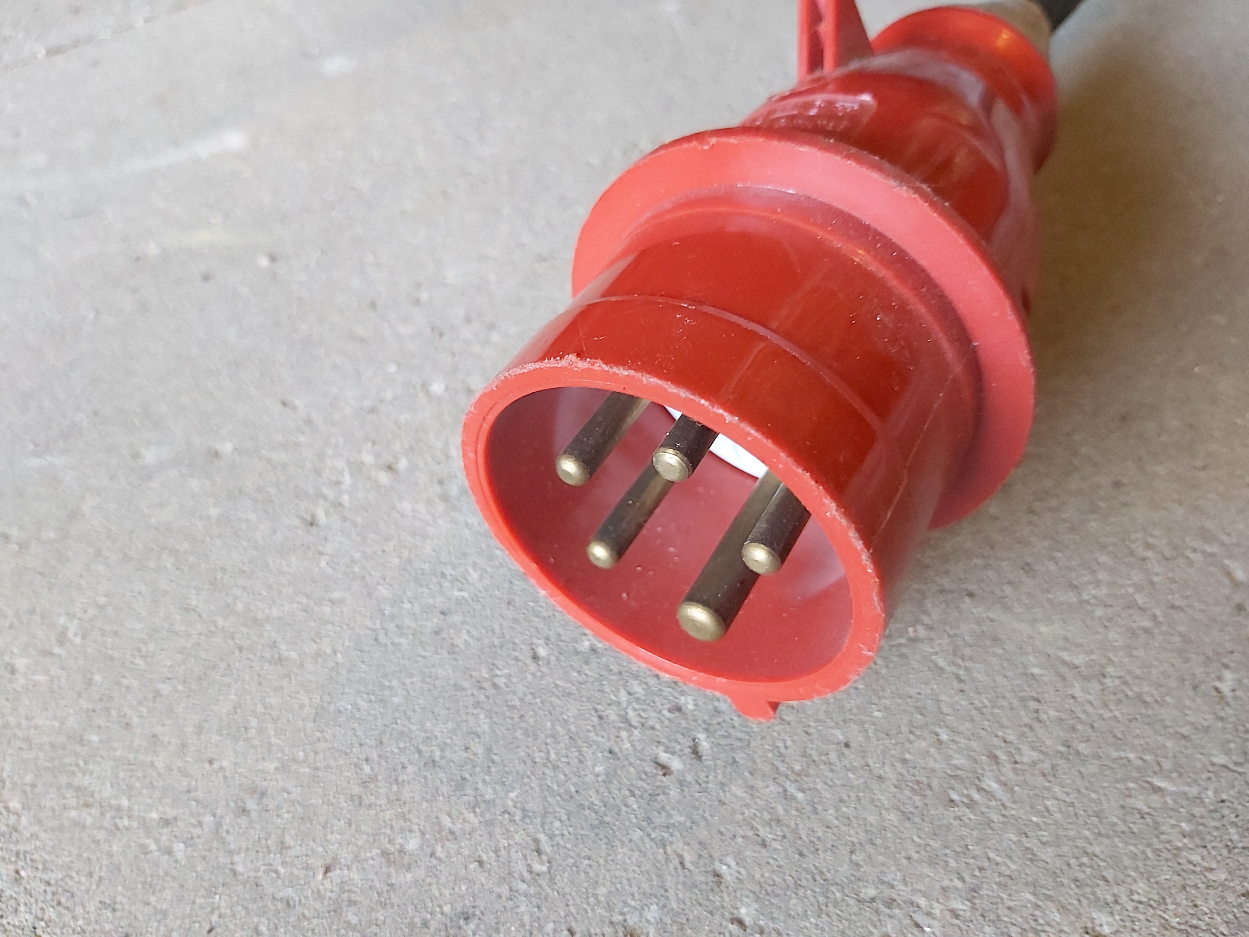
In northern and central Europe, residential electrical supply is commonly supplied with 400 V three-phase electric power, which gives 400V between phases and 230 V between any single phase and neutral. This three phase power system is called THREE-PHASE STAR; FOUR-WIRE; EARTHED NEUTRAL system. Electric power distribution throughout Finland and many parts of Europe is made by 230/400Vac, 3 phase, four wire, Multiple Earth Neutral (MEN). Typically one or three phases are brought into the customer’s premises depending on the maximum demand. Three phase power is normally available in at least Finland, Sweden and Germany being used for ovens, electric stoves, large motors and dryers. Three phase power is also typically available in places where large sound and light systems are used (around stages etc.) and in construction sites. Three phase outlets typically use industrial CEE FORM connectors for three phase temporary power output (typically 3x16A or 3x32A).
When three phase power is used (for example in industrial applications, construction sites and concert AV systems) the most common connector type is five pin CEEFORM connector.
Safety issues on lamps sockets
Edison screw (ES) is a standard lightbulb socket for electric light bulbs. It was developed by Thomas Edison, patented in 1881. Edison screw has been the most commonly used light bulb socket for general lighting for very long time. In Europe the most commonly used Edison light bulb socket sizes are E27 (ES) and E14 (Small ES, SES) with right-hand threads.
For bulbs powered by AC current, the thread is generally connected to neutral and the contact on the bottom tip of the base is connected to the “live” phase. This works for fixed installed lights, but for lamps that are plugged in to the mains outlets, you don’t know which wire going to socket will be live or neutral. Or this reason a “safer Edison” light bulb socket has been developed and is commonly used. That socket has contacts on the bottom and not connected to scree threads (that can be made of metal or plastic). Having the contacts on the bottom of the socket makes the light socket safer to handle when changing the light bulb.
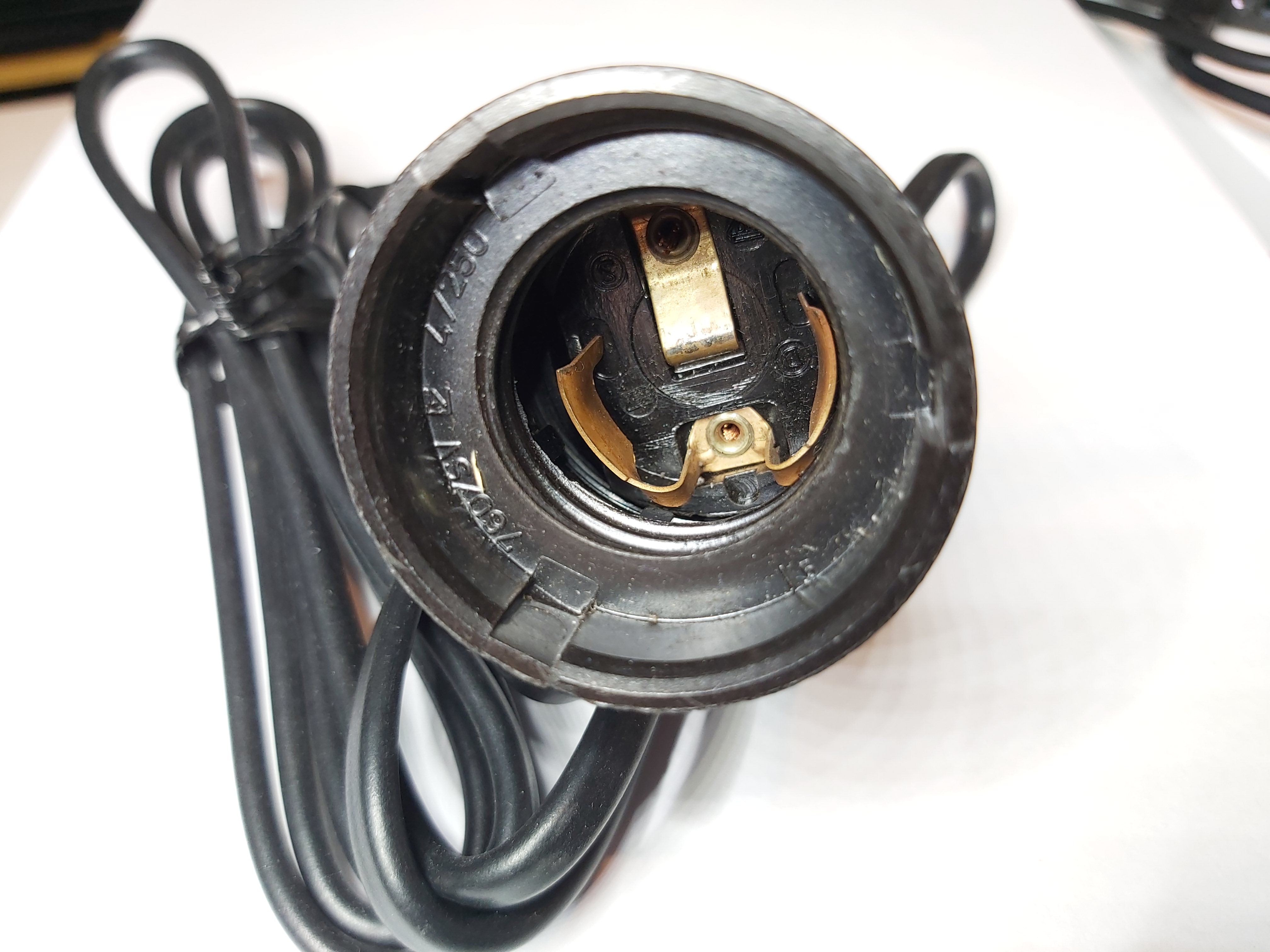
The bulb starts to makes contact with live and neutral contacts on the socket bottom only when it is screwed pretty much full into the socket. The bulb is screwed in at the time so much that the user can’t anymore tough the metal threads of the light bulb.
Wire size and fuses
In continental Europe the breakers/fuse sizes used in the breaker panel are normally 10A or 16A. The wire size inside the wall is normally 1.5 mm2 for outlets protected with 10A fuse/breaker. When the circuit used 16A fuse/breaker, thicket 2.5mm2 wire is normally used to them. The grounded outlets have three wires going to them: live, neutral and ground.
The extension cords are typically built using 1.5 mm2 flexible wire, because it can handle current up to 16A without heating too much (will get somewhat warm on full 16A). Long extension cords for heavy use sometimes use 2.5 mm2 wire thickness.
The cables feeding equipment are typically use 1.5 mm2, 1 mm2 or 0.75 mm2 wires depending on the power equipment uses. The 1.5 mm2 wire is OK for full continuous 16A current, while 1.0 mm2 can handle 10A. The thin 0.75 mm2 wire can handle only 6A current. Those thinner wires are allowed and even safe even on circuit protected with 16A breaker/fuse on the conditions that the equipment being powered is protected so that it can’t take more power than the wire can handle (fuse inside rated to power it takes for example) and the mains cable when faces short circuit will trips the up to 16A fuse/breaker before the cable starts to melt.
Equipment design
All devices should be designed to expect live on both mains power carrying wires, because configurations where either one of them can be live or neutral are possible. Under the European Low Voltage Directive (which applies across the whole EU, the EEA and countries that follow CENELEC standards) all appliances brought to market have to be safe to use in either polarity.
The neutral side might not be near the ground potential. It’s also possible that you may have a neutral fault on a TN-C/TN-C-S system as used in the UK and Ireland etc, which could introduce a significant voltage on neutral. There are also installations where both mains wires can be live compared to ground (some locations in Norway, some old installations, some isolated power on hospitals).
Some appliances do not require an earth connection. They are known as type 2 and will have a symbol of a square inside a slightly larger square on the appliance label. Other clues (although not 100% reliable), are a plastic case or flat 2 core cable. Those dual isolated devices appliances are typically supplied with Euro plug.
For best electrical design safety it would be best that the mains switch switches both mains power wires to guarantee that there is no voltage present in the device when the power is turned off. If a double pole switch is fit for its purpose, voltage and current ratings not exceeded, it will usually be safer than a single pole switch. There is no problem if extension cord has “switched” hot and neutral.
In practical equipment there are many devices that do not switch both lines on mains switch. his indeed means that the power supply electronics is on ground or live potential, when switched off. But I don’t see a big problem here is the device is well built. Some issue pertains to the isolation of devices from live using single pole switches, internal fuses and breaker/cut-outs.
In some cases equipment can have dual fuses (one for each incoming mains wire) to make sure that there is always fuse on the live side. The lack of polarisation might explain why some regulatory regimes in Europe are keen on double pole breakers. Majority of equipment have only one fuse in the mains input, so depending the power plug direction, it might end to be at the live or neutral side. Once single phase 230v is supplied, the lack of polarisations means that on an appliance with a single pole switch, or a device containing an internal fuse/cut-out that there is a 50:50 chance that some parts of the circuitry will still be “live” if it’s turned off or the internal fuse blows or a cut-out trips. Be careful out there!
146 Comments
Tomi Engdahl says:
IMPACT DRIVER vs CONSUMER UNIT – The results are SHOCKING
https://www.youtube.com/watch?v=9zKDVI8ilFU
What happens when you use an impact driver to install a consumer unit? We know it’s a terrible way to carry out an electrical installation but we went ahead anyway.
Manufacturers of circuit breakers and consumer units receive lots of warranty returns caused by electricians using impact drivers. So we decided to see exactly what happens to the terminals inside a consumer unit, Lewden RCBO and an expensive Wylex AFDD.
With BS7671 amendment 2 just around the corner, the use of AFDD’s in consumer units is expected to increase. Is it worth the risk of damage using an impact driver on an expensive device?
00:00 What damage can an impact driver do
02:13 Clearly damaged
02:52 Stripped thread
03:51 Inside an RCBO
04:39 Inside an MCB
06:45 Lewden clearly show the torque setting
08:13 AFDD’s are coming..?
08:50 EV have tons of electronics
09:10 Inside an AFDD
Tomi Engdahl says:
https://helpfulcolin.com/mains-safety-issues-with-extension-cables-13-amp-plugs/
Tomi Engdahl says:
Markings on Electronic Cartridge Fuses
https://www.swe-check.com.au/pages/learn_fuse_markings.php?fbclid=IwAR1DDRqRv7KLLbB5l0yvyDLJUr3oskATG4Cj7w_kbyOuOlWdi72dgm2-KLY
Tomi Engdahl says:
The Secrets Of Making Electric Cables & Wires
https://www.youtube.com/watch?v=Go5CS33SYnw&list=PLmWOIPxaBWH69DCzfCzCXd8UnoCOmCUum
Twin and earth cables are used by electricians to wire most British homes. How are these BS6004 T&E cables made? Gary Hayers takes a trip to Doncaster Cables to explore the production process from raw materials through to finished cables.
Along the way, we discover the secrets which mean not all cables are created equal.
================================
TIME STAMPS
00:00 Twin & Earth cables
00:15 Copper drawing
01:39 Annealing
02:16 PVC compound mixing
03:40 Copper stranding for class 2 conductors
04:50 Inner core insulation extruding
06:10 Cable make-up and sheathing
06:40 Cable identification marking
06:58 Adding french chalk
07:55 Cable Stripping test
08:04 High voltage testing
09:11 Drum winding
09:40 CPR & Product labelling
10:00 Ready for dispatch
10:18 Cutting corners?
==============================
Tomi Engdahl says:
Safety PSA: Don’t use these cheap ‘universal’ adapters
They’re deathtraps, in more ways than one
https://www.zdnet.com/article/safety-psa-dont-use-these-cheap-universal-adapters/
Tomi Engdahl says:
Adapter safety
https://youtu.be/xNmRUuwPXIg
Tomi Engdahl says:
EN IEC 61439-2: Power switchgear and controlgear assemblies
https://www.gt-engineering.it/en/technical-standards/en-iec-standards/en-61439-22119556196/
The purpose of the standard EN IEC 61439-2 (low-voltage switchgear and controlgear assemblies) is to harmonize as far as practicable all rules and requirements of a general nature applicable to low-voltage switchgear and controlgear assemblies (focus on power center) in order to obtain uniformity of requirements and verification for assemblies and to avoid the need for verification to other standards.
EN IEC 61439-1 includes all prescriptions which could be considered common.
For each type of assembly that falls on this series of Standard, only two main standards are necessary:
– EN IEC 61439-1: General rules
– The specific assembly standard (Part 2; 3; 4; 5; 6).
The EN IEC 61439 includes the following parts:
a) IEC 61439-1: General rules
b) IEC 61439-2: Power switchgear and controlgear assemblies
c) IEC 61439-3: Distribution boards
d) IEC 61439-4: Assemblies for construction sites
e) IEC 61439-5: Assemblies for power distribution
f) IEC 61439-6: Busbar trunking system
The EN IEC 61439-1 applies to low-voltage switchgear and controlgear assemblies only when required by the relevant assembly standard as follows:
– Assemblies for which the rated voltage does not exceed 1000 V of a.c. or 1500 V in case of d.c.;
– Stationary or movable assemblies with or without enclosure;
– Assemblies designed for use in connection with the generation, transmission, distribution and conversion of electric energy, and for the control of electric energy consuming equipment;
– Assemblies designed for use under special service condition, for example in ships and in rail vehicles provided that the other relevant specific requirements are complied with;
– Assemblies designed for electrical equipment of machines provided that the other relevant specific requirements are complied with.
This standard applies to all assemblies whether they are designed, manufactured and verified on a one-off basis or fully standardized and manufactured in quantity.
Tomi Engdahl says:
BS EN 62560:2012+A11:2019
https://www.en-standard.eu/bs-en-62560-2012-a11-2019-self-ballasted-led-lamps-for-general-lighting-services-by-voltage-50-v-safety-specifications/
This standard BS EN 62560:2012+A11:2019 Self-ballasted LED-lamps for general lighting services by voltage > 50 V. Safety specifications is classified in these ICS categories:
29.140.30 Fluorescent lamps. Discharge lamps
This International Standard specifies the safety and interchangeability requirements, together with the test methods and conditions required to show compliance of LED-lamps with integrated means for stable operation (
a rated wattage up to 60 W;
a rated voltage of > 50 V up to 250 V;
caps according to Table 1.
The requirements of this standard relate only to type testing.
Recommendations for whole product testing or batch testing are identical to those given in Annex C of IEC 62031 .
Tomi Engdahl says:
Halogeenittomat kaapelit ja niihin liittyvät säädökset
https://etn.fi/index.php?option=com_content&view=article&id=15274
Kaapeleiden ja johtojen ominaisuuksien luetteloista löytyy usein ”halogeenittomuus”, ”itsestään sammuva” tai kaikenlaisia ”salaisia” lyhenteitä, kuten LSZH. Mitä ne oikein tarkoittavat? Selitämme tässä.
MITÄ ”HALOGEENITON” TARKOITTAA?
Halogeenit ovat fluori, kloori, broomi, jodi ja astatiini. Ne ovat suoloja muodostavia kemiallisia alkuaineita ja osa vahvoja happoja, mukaan lukien suolahappo. Kaasumaisena aineena sekä palamisesta muodostuvina savuina aineet ovat sen verran myrkyllisiä, että ne aiheuttavat hengenvaaraa. Ainesominaisuuksien ansiosta halogeenit soveltuvat erinomaisesti monien muovien valmistukseen. Kaapeleissa kyseisen muovit ovat eristyksen ulkokuoria. Materiaaleista yleisin on polivinyylikloridi (PVC), joka on klooriyhdiste.
Jos aineessa ei ole halogeeneja aineen palamisen yhteydessä syntyvän savun myrkyllisyys on vähentynyt. Tämä on hyvin tärkeä paloturvallisuuteen liittyvä ominaisuus. Palossa sisätiloja täyttävä savu on yhtä vaarallista kuin tuli ja kuumuus. Sen takia halogeenittomien materiaalien käyttöön panostetaan – erityisesti kun kyse on asuntoihin, toimistoihin, autoihin ja rautatiekalustoon tarkoitetuista kaapeleista. Hyödynnämme sitä, että viime vuosikymmenien kemiallinen tutkimus on tuottanut useita vaihtoehtoisia materiaaleja, joilla on rajoitettu myrkyllisyys. Tätä seurasi halogeenittomien kaapeleiden tuotannon kustannusten huomattava lasku.
LSZH
LSZH on englanninkielisistä sanoistaLow Smoke Zero Halogen muodostettu lyhenne ja se tarkoittaa savutonta ja halogeenitontaainetta.
FRNC
Tämä lyhenne tulee englanninkielisistä sanoistaFlame Retardant, Non Corrosive. Se tarkoittaa sitä, että eristys onitsestään sammuva (se ei levitä liekkiä) eikä se sisällä syövyttäviä yhdisteitä, mikä käytännössä tarkoittaa, että valmistukseen on käytetty halogeenittomia aineita. Tulen kanssa kosketukseen jouduttuaan tällaiset kaapelit tuottavat pääasiassa vesihöyryä ja hiilidioksidia.
ERISTYSMATERIAALIT
Kaapeleihin ja paloturvallisuuteen liittyen avainkysymys on se, mistä materiaalista eristys valmistetaan, ja tässä vaiheessa on tarpeen tarkastella ulkopinnoitteisiin käytettävien aineiden ominaisuuksia. Kaikki materiaalit tavallaan vähentävät höyrymyrkytysriskiä tai ainakin lisäävät kaapeleiden lämmönsietokykyä. Niillä on muitakin ominaisuuksia, jotka on syytä ottaa ostettaessa huomioon.
EPDM
EPDM on etyleenipropyleenidieenikumi, eli eräänlainen synteettinen kumi. Sen tärkeimpiä ominaisuuksia ovat kuuman veden ja vesihöyryn kestävyys sekä alkoholikestävyys. Sen takia aine soveltuu mm. autojen jäähdytysjärjestelmienletkujen valmistukseen. EPDM:ista valmistetut kaapelit kestävät UV-säteilyä ja niiden ikääntyminen sään vaikutuksen seurauksena on rajoitettua.
(Silloitettu) polyeteeni
Polyeteeni on termoplastinen muovi, joka sen joustavuuden, mekaanisten ominaisuuksien ja lämpösuorituskyvyn ansiosta soveltuu erityyppisten kaapeleiden valmistukseen. Sitä käytetään usein silloitettuna. Tämä tarkoittaa, että valmistuksen aikana muovia vahvistetaan elektronisuihkulla.
PUR
Polyuretaanieristykselle on ominaista, että se pysyy joustavana laajalla lämpötila-alueella. Sen mekaaninen lujuus on myös oikein hyvä (mukaan lukien kestävyys hankautumiselle), materiaali on lisäksi UV-säteilylle, eli auringonvalolle kestävä. Valitettavasti sen rakenteen takia alttiina hydrolyysille (eli aineen hitaalle hajoamiselle veden kanssa tapahtuvan reaktion vaikutuksesta), PUR-eriste ei kestä kosteutta.
Silikoni
Silikonieristeiset kaapelit ovat kalliimpia, mutta erittäin lujia. Eduista mainittakoon korkea leimahduspiste, kestäviin useisiin kemiallisiin yhdisteisiin, laaja lämmönkestävyysalue (enimmissään jopa yli 200°C) sekä erittäin hyvä joustavuus. Laatunsa takia silikoinieristeiset johdot soveltuvat käytettäviksi mittaus- ja asennuslaitteissa.
CPR ja standardi EN50575
CPR-direktiivi (englanniksi:Construction Products Regulation) on voimassa EU-maissa. Sen päätavoite on säännellä rakentamisalalla käytettäviä materiaaleja koskevia asioita, erityisesti niiden liekkialttiuden ja palossa käyttäytymisen osalta. Lainsäätäjä on direktiivissä säätänyt kaapeleiden luokittelusta leimahduspisteen, palamisen aikana näkyvien kemiallisten yhdisteiden jne. perusteella. Säännösten perusteella voidaan määrittää tarkasti mihin luokkaan (”euroluokkaan”) tietty tuote kuuluu. Luokittelua varten suoritetaan laboratoriotestaukset EN50575-normin mukaan. Kaapeloinnin käyttäjien (esim. rakennusfirmojen ja sähköasentajien) on hyvää kiinnittää huomiota erityisesti kahteen kaapelityyppiin: Ecaja Dca. Niistä ensimmäiseton hyväksytty käytettäväksi omakotitaloissa, autotalleissa, maa- ja metsätiloissa. Dca-kaapeleita koskevat vaatimukset ovat tiukemmat. Niitä saa käyttää monikerroksisissa ja korkeissa rakennuksissa (usean kerroksen rakennuksissa), kouluissa, päiväkodeissa sekä julkisissa tiloissa. Kannattaa kuitenkin ottaa huomioon, että tällaisia kaapeleita ei saa käyttää hätäpoistumisreiteillä. Hyville tuotemerkeille on tyypillistä, että saatavilla on erilaisia aurinkosähkö-, asennus-, ohjaus-, kaiutin- ja viestintäluokkavaatimukset täyttäviä kaapeleita.
SYTTYVYYSLUOKAT JA -LUOKITUKSET
Viimeisenä kaapeleiden turvallisuuteen ja CPR-normiin liittyvänä käsitteenä on käsiteltävä niiden syttyvyysluokkia. Syttyvyys merkitään erilaisilla merkeillä. Niistä yleisimmät perustuvat normeihin UL94 ja ECE R-118.
UL94
UL94 on amerikkalainen standardi, jolla pystytään ennakoimaan, kuinka eri aineet käyttäytyvät tulipalossa ja itse asiassa – minkä tahansa kosketuksessa liekkien kanssa. Kyse on moniasteisesta muovimateriaalien luokituksesta. Kaapeleiden eristyksessä ovat useimmiten käytössä UL94V-0 ja UL94V-2 -merkinnät. Niistä ensimmäisellä merkitty kaapeli sammuu 10 sekunnin kuluessa liekin poistamisesta.
matalampi – V-2 tarkoittaa, että voi esiintyä palavia hiukkasia ja itsesammutus kestää 30 sekuntia.
ECE R-118
118-merkintää käytetään eri maissa, koska se perustuu YK:n asetukseen nro 118. ECE tarkoittaa tässä Yhdistyneiden kansakuntien Euroopan talouskomissiota (United Nations Economic Commission for Europe). Määräyksen tarkoituksena on yhdenmukaistaa kansainväliset henkilöautojen valmistuksessa käytettävien materiaalien syttyvyyteen liittyvät tekniset säännökset. Kyse on ennen kaikkea matkustamojen elementeistä, kuten ovista, lattioista, kojelaudoista jne. Nykyään ne kaikki ovat tietenkin sähköelementtejä, ja niihin asennetaan erilaisia antureita, kytkimiä, elektronisia järjestelmiä, toimilaitteita yms. Niistä kaikkien on oltava edellä mainittujen säännöksien mukaiset ja sama vaatimus koskee myös kaapeleita: kaikkia lattiaan ja kattoon asennettavia johdinnippuja, kaiutinkaapeleita jne.
ECE R-118-normin mukaisuus on yksi_autoteollisuuteen_tarkoitettujen kaapeleiden pääominaisuuksista.
Tomi Engdahl says:
SÄHKÖKESKUKSEN SUUNNITTELUOHJE
https://trepo.tuni.fi/bitstream/handle/123456789/26494/Salminen.pdf?sequence=4
Tomi Engdahl says:
UK Parliament To Act On This Circuit Fault Danger
https://www.youtube.com/watch?v=A4fVraZIv6w
Concern over Neutral Current Diversions is taking on national importance this week as the risks are raised in parliament…
…electricians are asked to be on the look out for a huge quantity of stolen cables…
…and the government introduces its long awaited tool theft law – but does it fall short of what the trade needs?
Welcome to Electrical News Weekly in association with The Electric Heating Company, whether you’re listening in the van, on-site, or down at the wholesale counter.
============================================
Time Stamps
00:00 Electrical Industry News – Monday 25th September
00:38 Risk of neutral current diversions raised in parliament
03:39 Tool theft bill has been approved
04:18 £30,000 worth of cable stolen from College
04:41 Paperwork no longer needed to drop waste off at wholesalers
05:10 91% of you have had an electric shock
05:46 Yepic – a new way to manage jobs
06:10 Ideal industries launches latest push in range of wire connectors
06:32 UK electrician triumphs in black pudding throwing championship
06:58 Thanks to our sponsors
============================================
Tomi Engdahl says:
Where Can You Use 90°C Insulated Cable?
https://www.youtube.com/watch?v=F1FaxdKQ7kg
In this video, we discuss XLPE insulation, and how it provides a higher operating temperature of 90°C compared to PVC, which has an operating temperature of 70°C.
Electricity running through a conductor causes heat, and the more current flowing through it, the hotter it gets. Because electricity is dangerous, we cover our conductors with insulation – made from various materials such as PVC, XLPE, silicon, and even minerals like magnesium oxide.
However, these insulators have their limits and start to degrade or melt when subjected to temperatures beyond a certain point. For instance, PVC starts melting at temperatures higher than 70°C, while XLPE can withstand up to 90°C.
In this video, you will learn the uses for XLPE cable, the importance of ensuring that your electrical equipment is rated to operate at the same temperature as your installed cable and a method to make use of the extra current carrying capacity of 90°C cable to save you money.
================================
Time Stamps
00:00 Where can you use 90°C insulated cable
00:47 Lets refresh ourselves on the basics
01:51 Where do you come across XLPE?
02:00 information on how much current 90°C insulated cables can handle.
03:42 Max operating temperatures also apply to conductors in switchgear and wiring accessories
04:46 You have to check if the electrical equipment you’re connecting to is rated at the same temperature
05:28 The 70°C Limit is met if the live conductor size is chosen based on the current rating for 70°C cables of similar construction
06:15 We can make use of the extra current carrying capacity of 90°C cable
07:10 This can be a cheaper installation option
================================
Tomi Engdahl says:
Most Electricians Don’t Know This Conduit Bending Trick
https://www.youtube.com/shorts/pUGg6CMs-xI
Tomi Engdahl says:
Check for diverted neutral current before a Ze test
https://www.youtube.com/watch?v=uQjj4GKeJQE
Diverted Neutral Current Demonstration – Normal, Open CNE, Current Circulation (Part 2)
https://www.youtube.com/watch?v=fen8ekrhlBI
Tomi Engdahl says:
John Ward
@jwflame188K subscribers533 videos
Electrical theory, experiments and demonstrations.
https://www.youtube.com/@jwflame
Tomi Engdahl says:
Diverted Neutral Current – Description Overview Part 1
https://www.youtube.com/watch?v=0nEsrlLpOzs
Diverted Neutral Current Demonstration – Normal, Open CNE, Current Circulation (Part 2)
https://www.youtube.com/watch?v=fen8ekrhlBI
Tomi Engdahl says:
Earth Electrodes Part 1
https://www.youtube.com/watch?v=FSG77GwrEds&list=PLVsHvs2SuqmoGuQa4SNL9FOYjHhGmTZ9G
Earth Electrodes Part 2 – Installing, Loop Impedance Testing
https://www.youtube.com/watch?v=_BkN8fRLYXw&list=PLVsHvs2SuqmoGuQa4SNL9FOYjHhGmTZ9G&index=2
Earth Electrodes – 3 Wire Testing Example (Part 3)
https://www.youtube.com/watch?v=K0P5wGSjxLE&list=PLVsHvs2SuqmoGuQa4SNL9FOYjHhGmTZ9G&index=3
Earth Electrodes Part 4 – Testing in Dry Soil (June vs November)
https://www.youtube.com/watch?v=moGlwuTYq8o&list=PLVsHvs2SuqmoGuQa4SNL9FOYjHhGmTZ9G&index=4
ConduDisc Demonstration – Earth Rod Alternative
https://www.youtube.com/watch?v=VKJ3gwFnxEw&list=PLVsHvs2SuqmoGuQa4SNL9FOYjHhGmTZ9G&index=5
ConduDisc and Conducrete Installation
https://www.youtube.com/watch?v=tYcXE9W2AKQ&list=PLVsHvs2SuqmoGuQa4SNL9FOYjHhGmTZ9G&index=6
Tomi Engdahl says:
Broken PEN conductors and Diverted Neutral Currents – How to check for and mitigate them
https://www.youtube.com/watch?v=2NQzFwZupiY
Tomi Engdahl says:
The WAGO Junction Box Debate: Metal or Plastic?
https://www.youtube.com/watch?v=E2p5ZZJNp30
Tomi Engdahl says:
The mains panel breaker protects against short circuit and overload of behind the wall wiring. It will also protect against short circuit in equipment wiring, but will not provide adequate overload protection for thin cables. For thin cables there should be an overload protection fuse or other similar means that prevents long time overload from happening.
Tomi Engdahl says:
Sauna palaa Suomessa lähes joka päivä – kiulu jää kiukaalle, pyykkinaru pettää, kiuas on väärin kiinnitetty…
Saunatiloissa syttyy Suomessa tulipalo noin 400 kertaa joka vuosi. Onneksi saunapalot johtavat vain harvoin kuolemiin.
https://yle.fi/a/3-9917586
Tomi Engdahl says:
Plugs and Sockets in Europe
map and compatibility table
https://www.plugsocketmuseum.nl/EuropePlugsSockets.html?fbclid=IwAR3_3Y9jwIANGYDMX4eJmyEF3CipT9UFbDWAXdOgrd4qjiN8XM9l1jbvoJQ
Tomi Engdahl says:
https://www.plugsocketmuseum.nl/index.html
Tomi Engdahl says:
Single phase is always 230V, 3 phase is always V. All 50Hz. Common connector currents are 16A, 32A, 63A, 125A, 200A, 400A.
what’s complicated about US power? Single phase 120, 3-phase 208. Common connectors are 15A, 20A, 30A, 50A, 100A. Need high voltage to step down? 277/480 to a transformer. Maybe to a European it’s confusing… but really, it’s not that remarkably different.
Japan that has some cities at 50 Hz and others at 60Hz.
Tomi Engdahl says:
Powerlock if you need ALOT of power, and an abundance of CEE 16,32,63 and 125A 3 phase
Tomi Engdahl says:
Because UK designed their electrical distribution in such way that instead of many fuses/breakers in mains panel and many wires to outlet, there is one high current “ring mains” and fuses in plugs. Design choices.
Tomi Engdahl7 says:
UK
Erich Lehner
” a common arrangement is to use the 2.5 mm2 Twin&Earth cable protected by a 32A Type B MCB. This arrangement allows for the coverage of 100 m2″
https://www.sparkyfacts.co.uk/Wiring-Diagrams-Ring-Circuit-Wiring.php#google_vignette
Tomi Engdahl says:
https://www.fatallyflawed.org.uk/html/other_dangers.html?fbclid=IwAR05_mKqcHXjVIlrK1IV989KAK3m1YbrTfrMLpVhh8CT2MTfoahUPviE_gU
British extension sockets also have to meet BS 1363 and therefore they also include internal safety shutters.
However, there is a loophole in the standard which is exploited by many manufacturers allowing them to make extension sockets so slim that it is possible to put an inverted normal plug into the earth pin only, this results in the shutters being held open with the live contacts accessible, as shown in these pictures. FatallyFlawed has brought this to the attention of the relevant authorities, however there appears to be no interest from either the BSI or the responsible government department to correct this oversight.
Tomi Engdahl says:
How Italians Got Their Power
https://hackaday.com/2024/05/18/how-italians-got-their-power/
We take for granted that electrical power standards are generally unified across countries and territories. Europe for instance has a standard at 230 volts AC, with a wide enough voltage acceptance band to accommodate places still running at 220 or 240 volts. Even the sockets maintain a level of compatibility across territories, with a few notable exceptions.
It was not always this way though, and to illustrate this we have [Sam], who’s provided us with a potted history of mains power in Italy. The complex twists and turns of power delivery in that country reflect the diversity of the power industry in the late 19th and early 20th century as the technology spread across the continent.
History of the Italian electrical system
https://samuele963.github.io/electrics/history.html
The Italian electrical system has a fairly complicated history; from different voltages and frequencies to the type of plugs used, almost everything about it has changed over the last century, or is in the process of changing.
This page documents this history, specifically regarding the situation in Italy, and the various changes that happened over time as the electrical system evolved.
As with most countries, electrical supplies in the early days of electrification were divided between different regions and even across cities, as grids were owned by many small regional power companies; thus, voltages and frequencies (42Hz was quite common) could vary a lot between each other.
The dual tariff system
During this time, electricity was mainly used for lighting, and later on also simple devices such as fans and radios. If you wanted to use any appliances you had to pay for a higher rate of electricity, which was metered and taxed differently – the idea was, that if you were rich enough to own, for example, a washing machine (which was very expensive at the time), you definitely had enough money to pay for the appliances supply.
To prevent people from using the cheaper lighting supply for appliances, this was powered at a different voltage – for example, 120 or 150V – and often was also limited to only a few kilowatts. Appliances, on the other hand, used a higher voltage, generally 220V (though 260V was also a thing), which also helped with efficiency.
As a result of this, some electrical devices made back then aren’t usable now without a transformer to step down the voltage – this is quite common on smaller tube radios and fans which were meant to be used with the lighting supply. Other devices, instead, had voltage selector taps on the back – some of these were for 120/150V-only, but often these also included an option for 220V (for tube radios, this was generally the case for ones with a built-in transformer), which makes it possible to use them even today.
How these supplies worked
The way this worked was quite simple: 127/220V three-phase transformers were common, which provided 120V between one of the phases and neutral, for the lighting supplies, and 220V between phases for the appliances supply. So, if you only needed to power lights, you received a single phase and a neutral, while if you also had an appliances supply you had two phases (or three phases for industrial applications) and a neutral, and two separate power meters.
This arrangement is somewhat similar to the electrical supplies used in North America nowadays, where 120V is used for most appliances and 240 or 208V is used for heavy appliances, though one major difference is that split phase was very uncommon here.
Two types of plug
An overview of the two different sized of Type L plug. Because of these dual supplies, and the two voltages they used, two different types of plug became common, and are nowadays both known as type L: a “small” 10A one meant for the lighting supply, and thus generally used for 120V, and a “big” 16A one meant for appliances, and thus generally used for 220V.
“Big” sockets were incompatible with “small” plugs and viceversa, a useful feature to prevent breaking your precious electrical appliances.
Moving to 220V
Over time, as electricity became common, more and more people bought electrical appliances and thus most houses had two power meters and both 120 and 220V sockets in their home. As time moved on, 220V became used for more and more things, and people began wiring up 10A socket for use on 220V (which lead to some interesting results when a 120V devices was plugged to a 220V socket); as such, the whole structure of “small” sockets being for 120V and “big” ones being for 220V slowly began to fall.
Additionally, even lighting supplies began getting migrated to 220V
Because of these dual supplies, and the two voltages they used, two different types of plug became common, and are During this time adaptors to go between the two different types of socket became common, and the purposeful lack of intercompatibility between the two went from a useful feature to a growing problem, especially as single-meter 220V supplies became more common.
On these installations, 10A sockets were often also used on the same exact circuits as 16A ones, making the separation even more pointless. A solution to this came in the form of the Bipasso sockets, 16A sockets which also accepted 10A plugs. These became more common for new installations, starting in the 70s-80s, solving the compatibility problem.
Nowadays 120V supplies are no longer a thing – the last one was shut down in Lazio in 1999, thus marking the end of that era, though by then they had become extremely rare already. However, certain elements of that legacy still remain: the most notable part is the use of the two type L plugs, as well as Schuko ones.
Additionally, some areas still use the old 127/220V transformers; houses in these areas receive two phases, both live at 127V with respect to earth. Special care must be taken in buildings fed by those transformers, to make sure proper double-pole (2P) breakers are used, to avoid things remaining live accidentally.
Tomi Engdahl says:
https://www.msn.com/fi-fi/talous/uutiset/tarvitsetko-adapteria-kun-l%C3%A4hdet-ulkomaille-matkailijan-s%C3%A4hk%C3%B6opas/ar-BB1mXMvX?ocid=entnewsntp&pc=HCTS&cvid=0a4310119aa9475cbabe185549fdb852&ei=27
Tomi Engdahl says:
From Facebook
does anyone actually use fuses anymore?
Depending on where you live, oh yes.
I used to live in Spain. Fuses there were just wires wrapped around posts. You set the value by counting the loops.
This was also common in France, you’d have a porcelain “tab” where you’d attach on two posts a fuse wire (with different thickness depending on the amperage rating) then that tab would be inserted into a matching receptacle. (that was before the cartridge-style fuses with either the screw-in caps or the receptacle where you’d pull a lever down, slide the cartridge in then push it back up)
This wire was often referred to as a “plomb”, which gave rise to the idiom “les plombs ont sauté” meaning that the fuse blew, even though fuses have mostly disappeared (EDF still use fuses before the metering unit), this idiom still lives on.
Hey. No potential for abuse there.
That there are still houses with screw in fuse panels should not be a shock.
https://www.facebook.com/share/p/5a4yg4oTeVpXqiqt/
Tomi Engdahl says:
https://www.electricaltechnology.org/2020/07/electrical-wiring-color-codes-nec-iec.html#google_vignette
Tomi Engdahl says:
Finland:
Generator whatever suitable, transformed to 110 kV
Main long distance transmission uses 400kV,220kV,110kV
Secondary transmission 110 kV
Primary distribution: 20 kV (and old 10kV)
Secondary distribution: 400V (400V between phases, 230V from phase to neutral)
Tomi Engdahl says:
Zig-zag transformers
https://www.edn.com/zig-zag-transformers/#google_vignette
Three phase power transformer secondaries that are set up in a delta configuration do not have an earthing or grounding point. By contrast, a wye configuration of windings would provide such a point, but delta windings are frequently the transformer designer’s choice (Figure 1).
Where the three coils of the wye configuration meet, a ground or earth connection can be established, but the three secondary coils of the delta configuration offer no such point.
In such cases, an earthing point can be established using a zig-zag transformer as in the following sketch in Figure 2.
Tomi Engdahl says:
-10% ja +5% eli 207v -242V välillä pitäis pysyä
Koska tämä on muuttunut? Minulla on sellainen tieto, että vaihteluraja on 230 V ±10 % eli 207 – 253 V. Jopa -15 % saa olla tietyn ajan.
Tomi Engdahl says:
Asennusprojekti: Jännitteettömät käyttöönottomittaukset (lisätty selostus)
https://m.youtube.com/watch?v=K6Ve8klyjw0
Tomi Engdahl says:
Doesn’t matter the socket, you can use the small euro plugs everywhere in Europe. The most important is that everywhere in Europe the electricity is ~220-230V, 50Hz.
well, in europe you got the big plugs with two pins and one ground, normally on washing machines, dishwasher, irons, work tools,… and the we have the “euro plug” for radio, tv, charger,…. which has 2 pins but no ground, it fits in any socket, you can use that in any european country besides uk
you can use it even in UK with little trick
Tomi Engdahl says:
well, in europe you got the big plugs with two pins and one ground, normally on washing machines, dishwasher, irons, work tools,… and the we have the “euro plug” for radio, tv, charger,…. which has 2 pins but no ground, it fits in any socket, you can use that in any european country besides uk
Tomi Engdahl says:
Excluding UK, they’re all compatible if there’s no ground.
Tomi Engdahl says:
Type F – Schuko (CEE 7/3) most popular EU electrical socket/plug. Type F – Schuko (CEE 7/3 and CEE 7/4) is most popular EU electrical socket/plug. Plug & Socket Type F is used in most EU countries, including Germany, Austria, the Netherlands, Spain, and others.
Tomi Engdahl says:
The Type C plug (also called the Europlug) has two round pins. The pins are 4 to 4.8 mm wide with centers that are spaced 19 mm apart; the plug fits any socket that conforms to these dimensions.
Tomi Engdahl says:
https://www.mennekes.org/industry/knowledge/for-electrical-engineers/norms-regulations/european-standards-for-plugs-and-sockets/
Tomi Engdahl says:
BS7909 states that a step down cable can be used providing the distribution has incoming protection rated at the same as the incoming connector and the cable is no longer than 3m. I’d say this passed both those tests. 13a should be kept dry though and it should be H07 rubber cable. Not ideal but not a deal breaker.
Tomi Engdahl says:
Ei voi olla varma, mutta on sovittu että 0 on vasemmalla ja ylhäällä.
Tomi Engdahl says:
https://hackaday.com/2019/04/14/a-peek-inside-a-typical-british-residential-power-panel/
Morgan Bwogi says:
Hello,
We are a sourcing and procurement company with very many clients within East and Southern Africa. We are sourcing on behalf of one of the buyers for a manufacturer, distributor, or reseller for the following products:
electric wires
Please quote the prices in USD for the above with CIF terms to Mombasa port. Thereafter we shall discuss with our client and then forward to you the details in which you will issue a proforma invoice.
Awaiting your swift response towards establishing a long-term relationship with your prestigious company.
Kind regards,
Morgan Bwogi
Sourcing Manager
Oriship Agency
Plot 35, 7th Street Industrial Area
Kampala, Uganda.
Tel: +256 758388646
Email: [email protected]