The CEE form, also known as CEEFORM, is an abbreviation of Certification of Electrotechnical Equipment. Ceeform is a certificate for electrical equipment. It was formerly published by a European body called Commission internationale de réglementation en vue de l’approbation de l’équipement électrique, which is now superseded by IECEE.
The “cee” in ceeform socket and ceeform plug refers to the standard of CEE17. CEE17 describes standards for plugs and sockets for industrial purposes. Although CEE17 standard has been superseded by IEC60309 since 1985, name still stays in use.
The CEEFORM socket and plug refer to the industrial sockets and plugs which comply with the following specifications: voltage below 1000 v, current below 800 A, frequency below 500 Hz and environmental temperature range −25 °C to 40 °C.
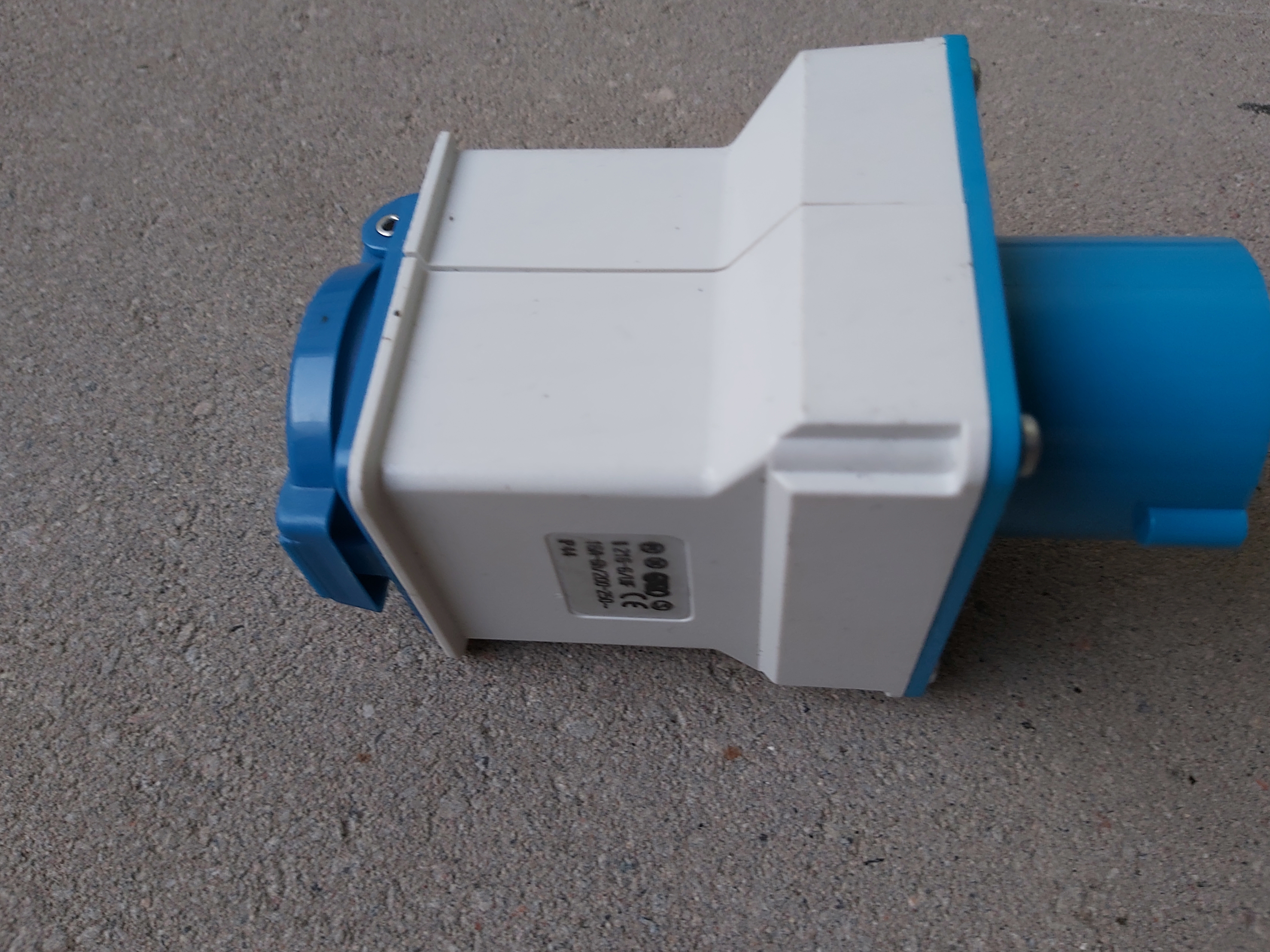
There are plugs and sockets for different environmental conditions. The most seen IP ratings for ceeform socket and plug on the market are IP44 splashproof and IP67 watertight. That IP44 is it is “spray proof”, it’s protected against rain and water spray from 180 degrees. Not waterproof, but usually has a system to drain water out and prevent water at critical places. When better protection is needed, there is also a screw-on lid type which is IP67 rated. It can be under water for 30 minutes at 1 meter depth.
There are different connectors for different voltage ranges and currents. For the current, there are widely used 16A, 32A, 63A, 125A. There exist also higher current products, such as 400A, 630A, even 800A, that are used for special occasions. Different current versions have different pin sizes and connector size.
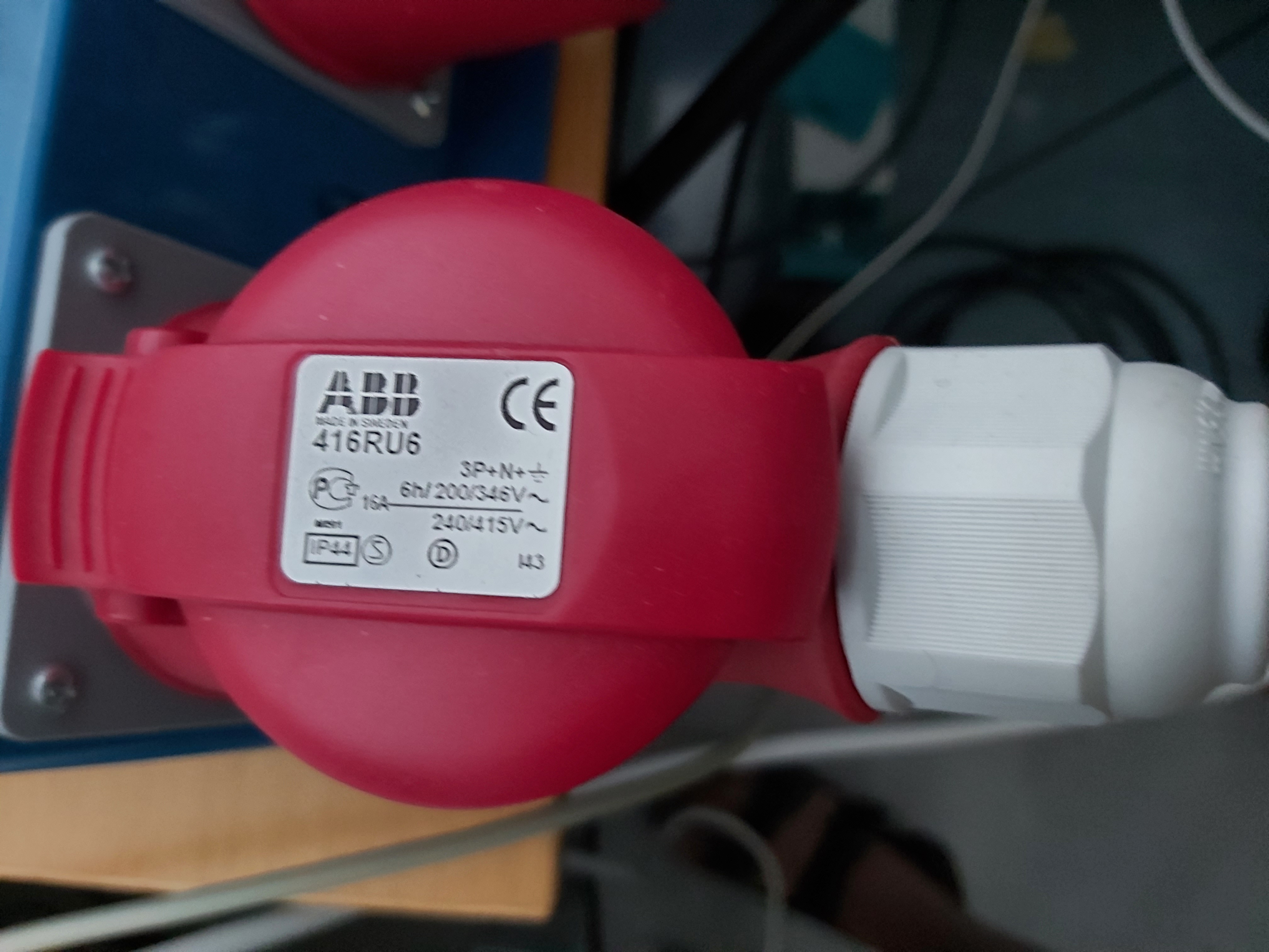
The voltage is divided in ranges, such as 100v-130v, 200v-250v, 380v-415v, etc. Different voltage versions use different pin coding and different connector case colors, so that users can determine what connector should be connected where and can’t connect plug to wrong socket. Each connector color is strictly connected with the voltage range (with some few exceptions). Check the connector color and pin mapping guide for more details.
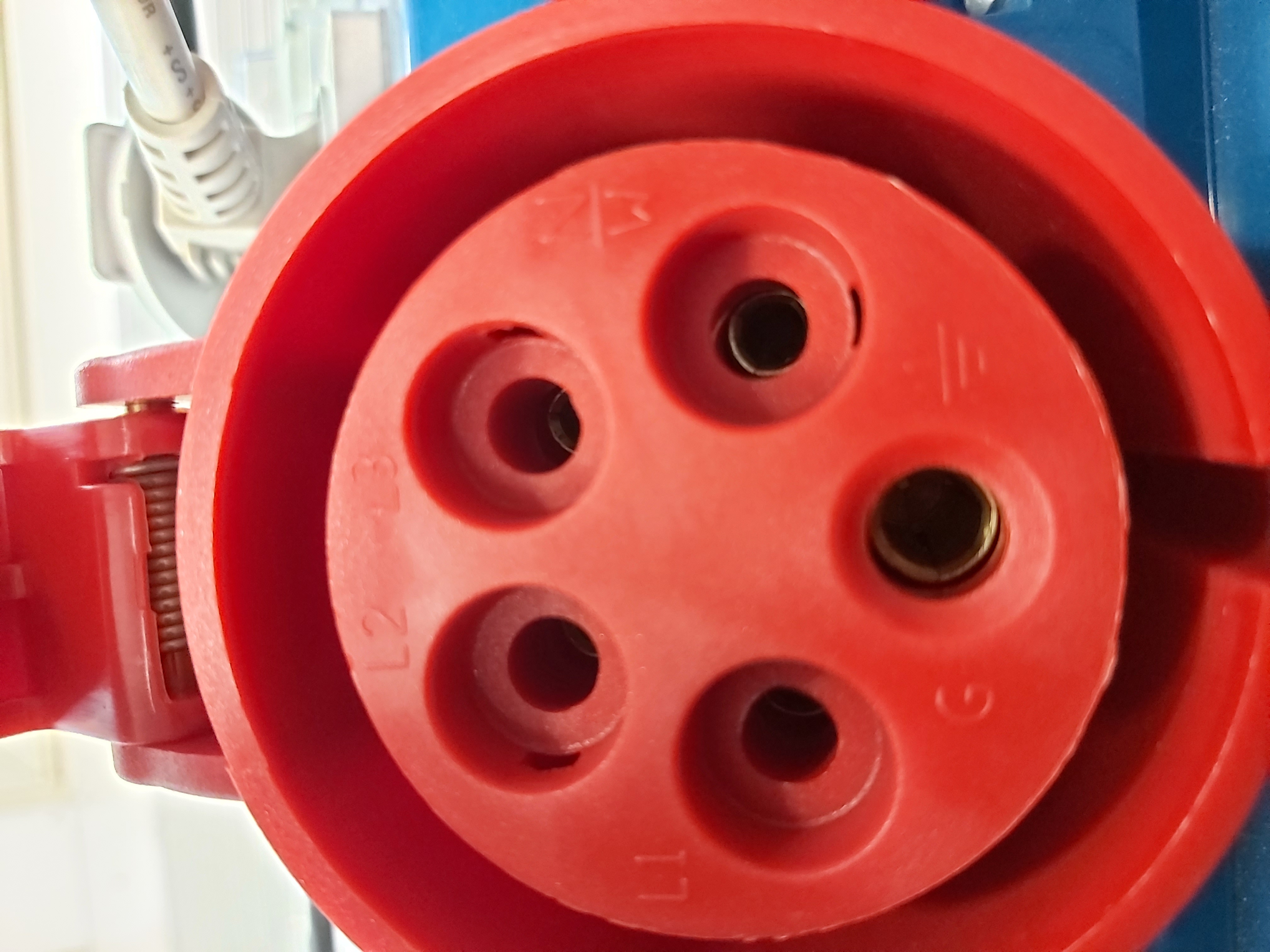
A ceeform plug can have as many pins as from 2 to 8, deriving various pin configurations, such as P+N+E (3 pins), 2P+E (3 pins), 3P+E (4 pins) and 3P+N+E (5 pins). The most commonly used connector types I have came across have been three pin connector for single phase power and five pin connector used for three phase power.
This article will show the connectors I have most seen used in Finland. Those same connector types are widely used throughout Europe for industrial applications.
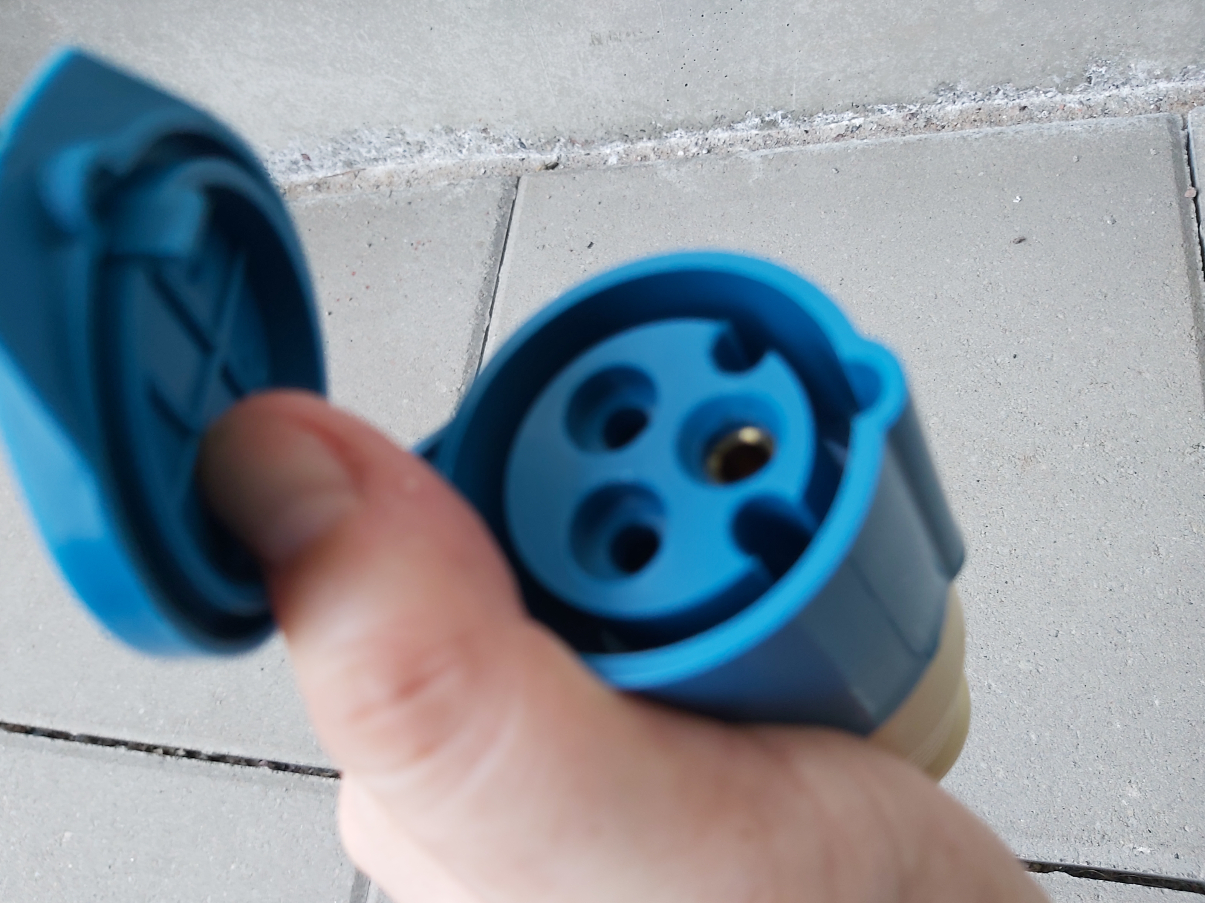
Blue 16 Amp 230V AC CEEFORM mains connectors is often used to carry normal single phase 230A mains power. Blue color can be used only for the ceeform socket and plug which has a voltage range of 200v – 250v.
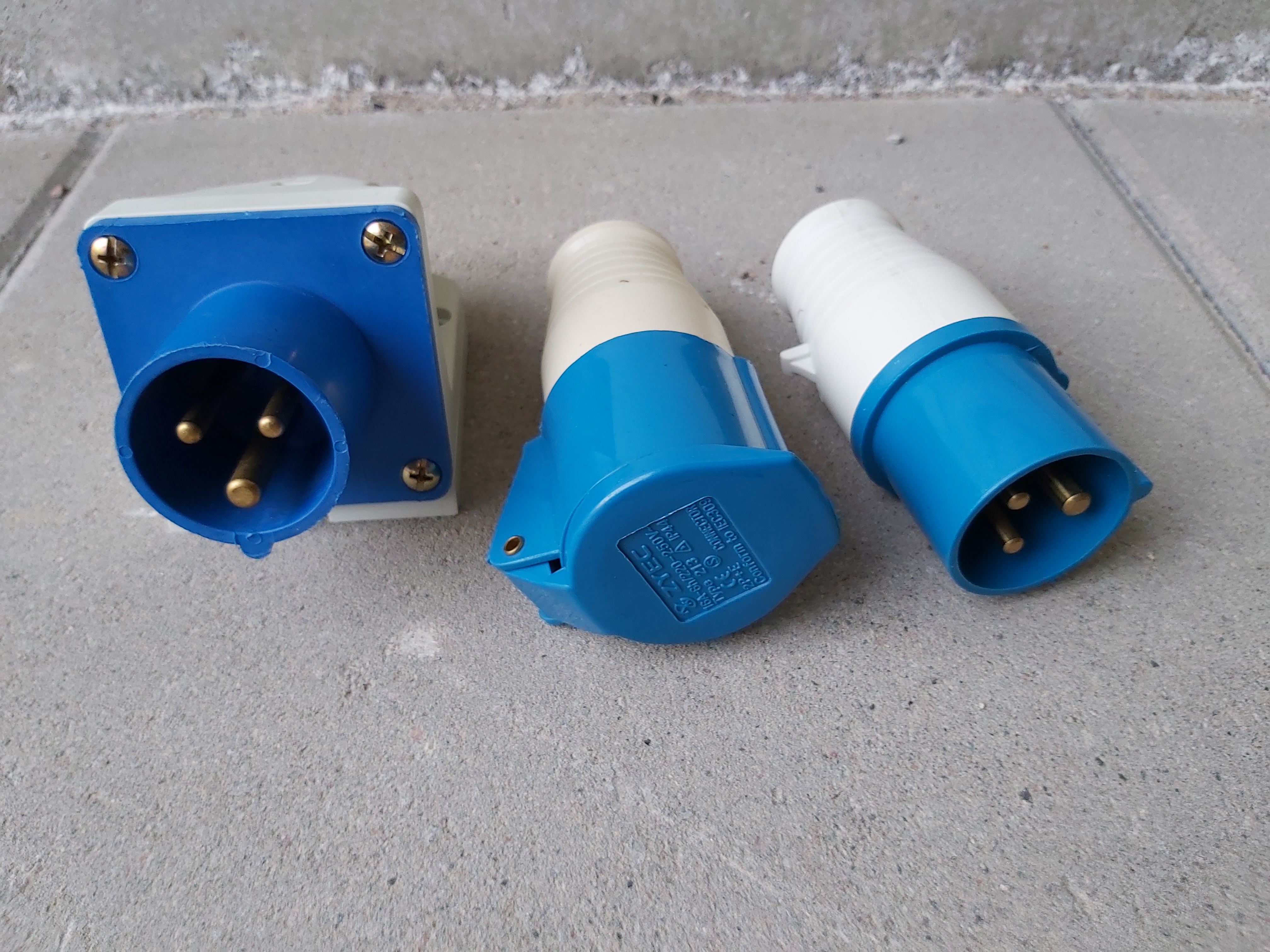
Those connectors are IP44 rated connectors suitable for general use. Those connectors are rated for continuous 16A current all the time. The marking “6h”is not hours of use, but indicating the subtype code for CEE plug telling that earth pin is at 6 o’clock position.
The lid on the plug works ad protection when connector is disconnected and also works as a simple locking mechanism to protect against accidental disconnection.
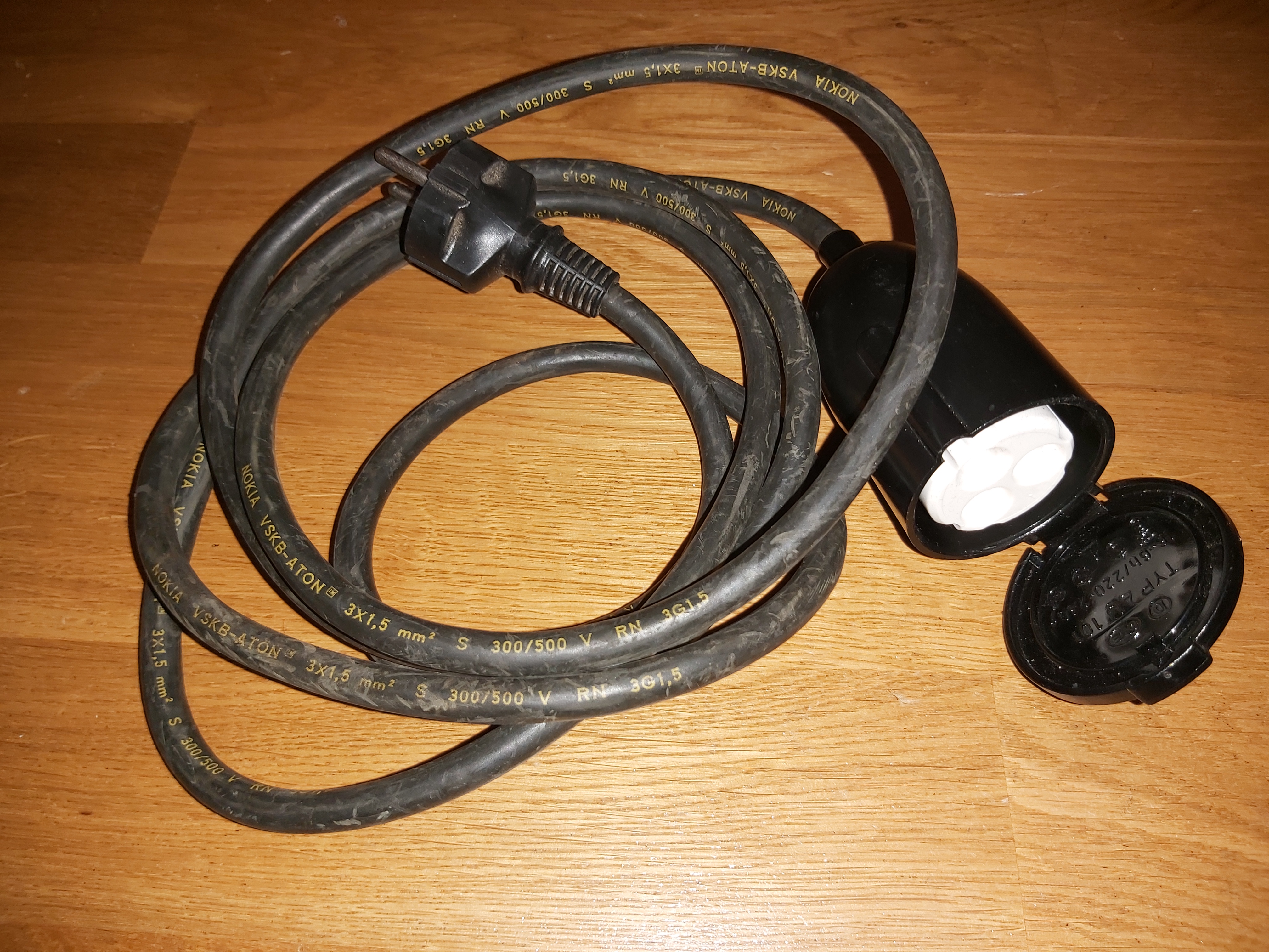
When the CEEFORM needs to be adapted to work with “normal” mains plugs like SCHUKO, adapter plugs or cables can be used to do that. The first adapter converts CEEFORM to normal SCHUKO outlet connector. The second adapter is a cable that converts SCHUKO male to the CEEFORM female plug. This connector is same as the blue plug (interconnects to blue connectors), but for some historical reasons has black color (is old car heating cable).
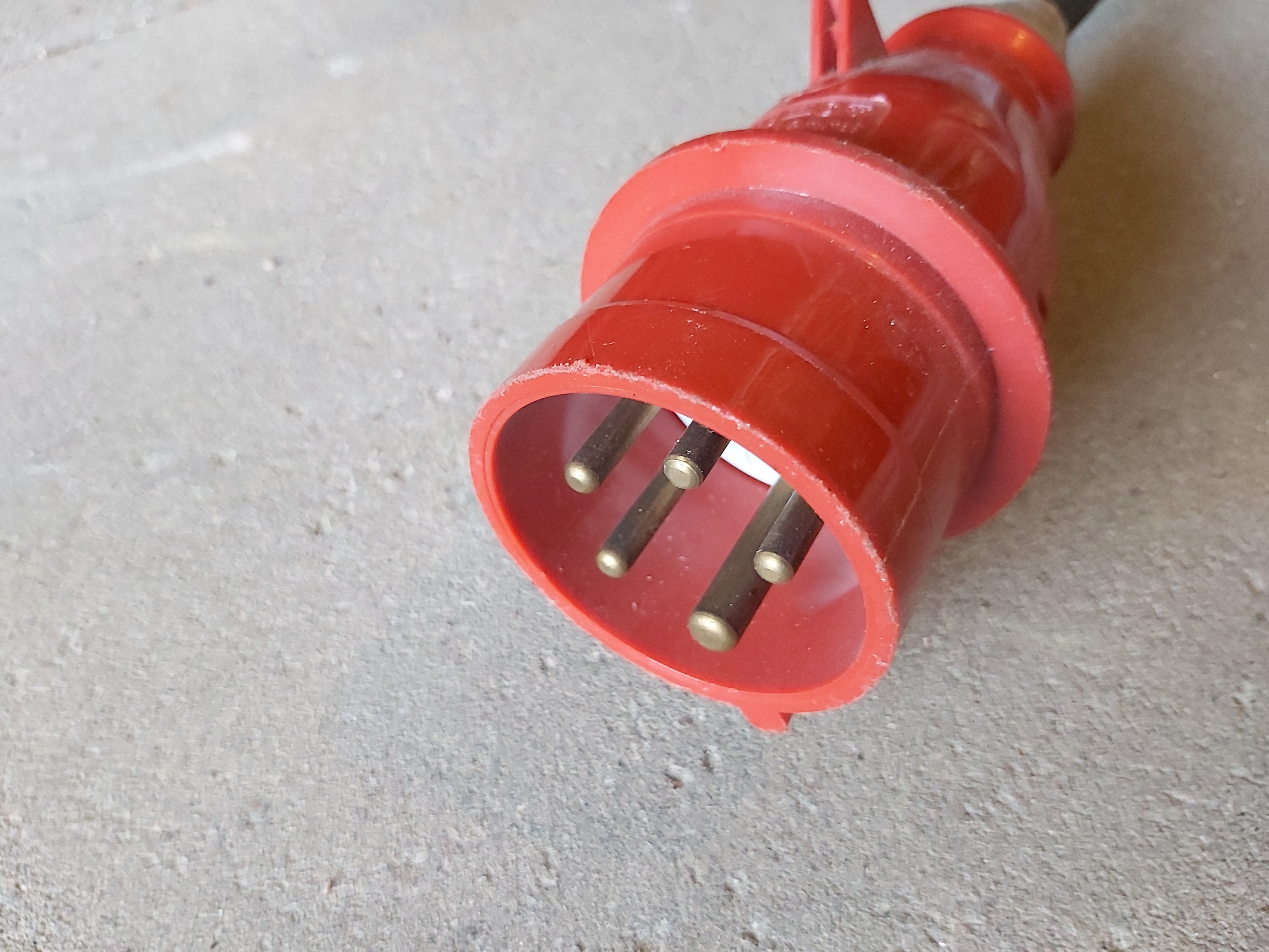
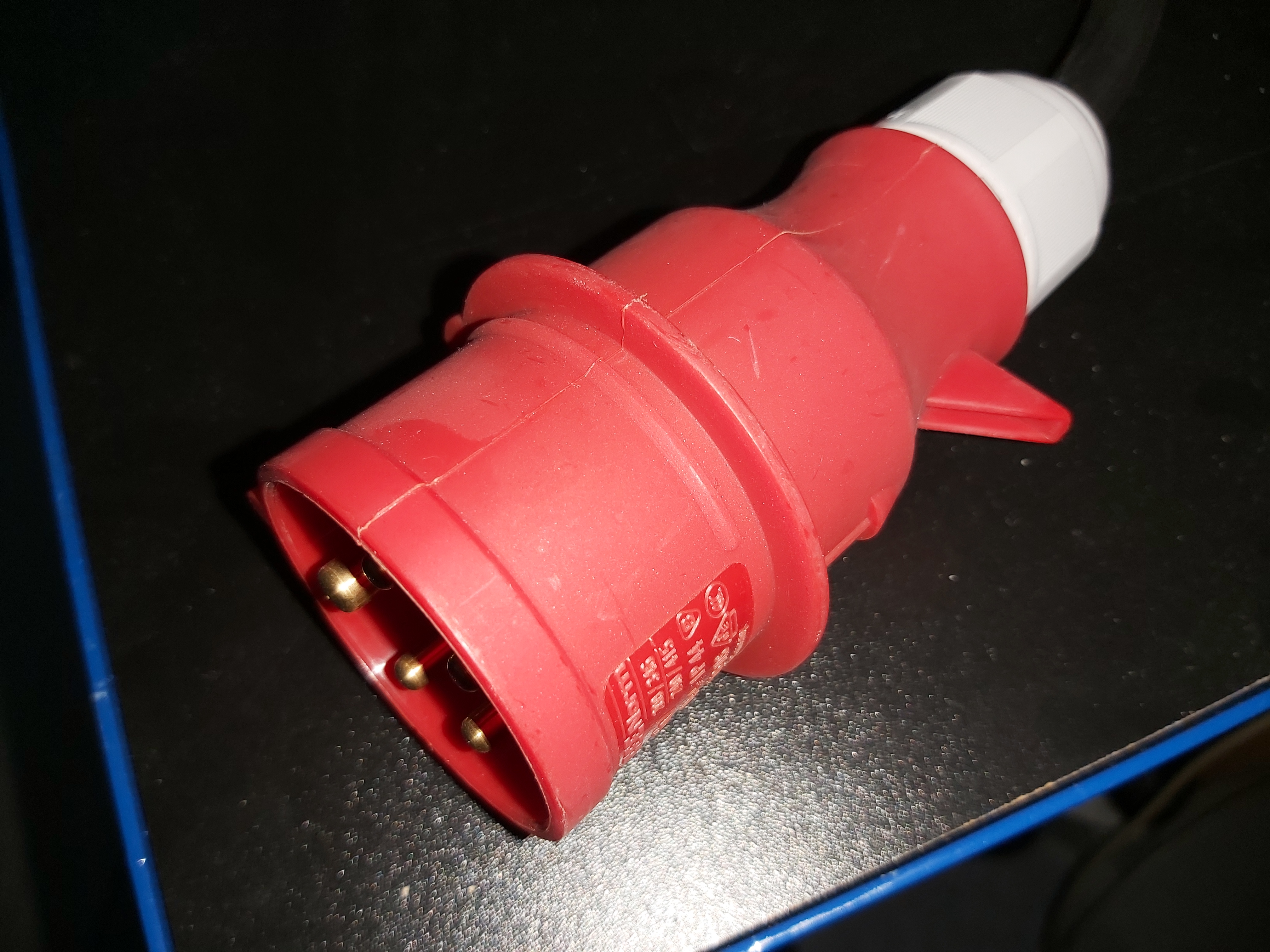
Here is 16A connector for three phase power.
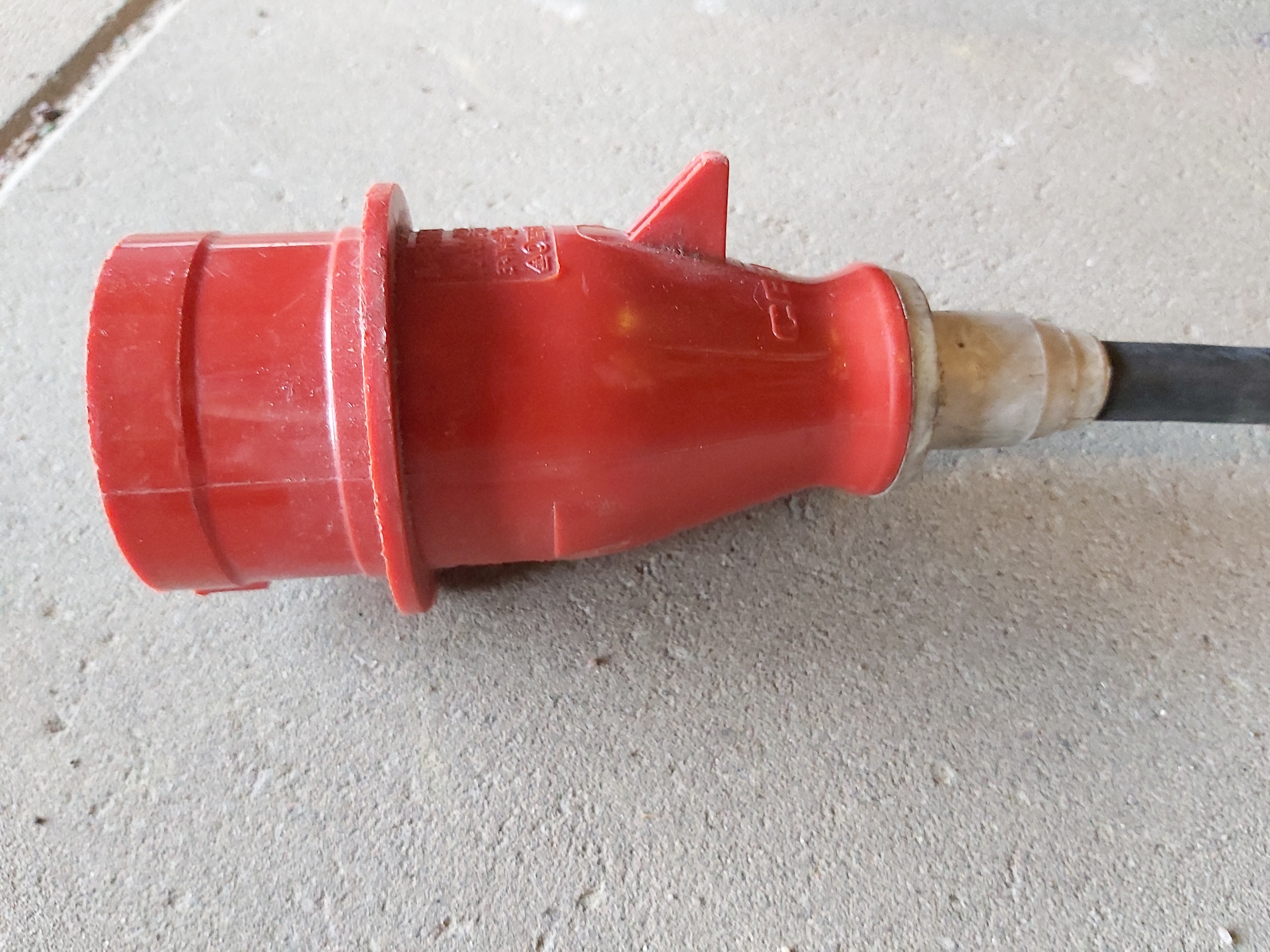
The widespread 400 V (between phases) three phase power network used throughout Europe has 230V from phase to ground. So called power splitters with this connector as a 3 phase inlet and 3 groups of single phase outputs are commonly used top get 230V power to single phase devices. Simplest adapter for 16A plugs can be just single phase outlets rated for 16A directly wired. For higher current separate breakers/fuses are typically needed.
The 16A CEEFORM connectors are fully rated for connecting and disconnecting under load. The higher current rating connectors are not rated for connecting and disconnecting under load, so you need to make sure you have the load current turned off when connecting and disconnecting the connectors. Some industrial applications use interlocked power outlets that prevent the plug connected/removed if power is turned on.
Generally you should be connecting and disconnecting three phase connectors it is best to do that when power feed and/or loads are disconnected.
The 5 pin connector is built so that it should guarantee that ground and neutral are connected before the live pins make contact. The male pins have same length, but the female connector has the different contacts starting at different depth.
I have been warned by electrician doing powet distribution for events that this plugging and unplugging is not always foolproof, so at worst case doing plugging and unplugging can potentially cause 400V spikes to hit single phase loads for short time because the connection of neutral before phases wire is not guaranteed. Best to plugging and unplugging carefully if you have expensive hardware (like computers) connected.
Videos
My favourite industrial connector (Ceeform).
https://www.youtube.com/watch?v=feCZs9YpH3M
Industrial Connector shoot out – XCEE vs the cheapest Wohnwagenstecker ceeform
CEE Form Industrial Connectors – What’s Inside
Industrial plugs and sockets (ceeform) – How it’s made factory tour
http://www.blue-room.org.uk/index.php?showtopic=37009
I believe (I’m sure someone will correct me in if I’m wrong) that 16A Ceeforms are the only connector on the market actually rated/designed for connecting and disconnecting under load?
https://m.facebook.com/groups/avdisasters/permalink/3864857456976070/
Looks horrible but not necessarily immediately dangerous. There seems to be breakers on those electrical panels, so if they are OK, they will trip before fire danger.
Those blue single phase CEEFORM industrial plugs are full time rated to 16A 230V, and the circuit should be protected with 10A or 16A fuse. If outputs are overloaded the breaker will trip before fire danger. Those ceeforms are much more reliable and better environmentally protected than normal home outlet connectors.
Those are industrial plugs that can withstand rain when used correctly. The installation direction has somewhat effect on the environmental protection of IP44 connector. Fixed connectors are usually installed angled downward to prevent water entering. I have seen cable connectors usually used so that the female connector is up and the female holed point down. This minimizes changes of water getting in from rain to IP44 version. If you have male as upper connector, water gets on more easily.
Links to more information:
https://www.ceesockets.com/knowledge/what-is-ceeform-cee-form-fully-explained/
https://www.ceesockets.com/wp-content/uploads/2018/07/color-code.jpg
https://www.ceesockets.com/knowledge/the-structure-of-ip67-industrial-plug/
https://www.ceesockets.com/knowledge/ip44-industrial-socket-structure/
https://www.ceesockets.com/knowledge/how-to-buy-industrial-socket-and-plug-from-china/
https://www.ceesockets.com/wp-content/uploads/2018/08/clock-map.png
http://www.blue-room.org.uk/index.php?showtopic=37009
https://www.ceesockets.com/knowledge/ip44-industrial-socket-structure/
https://www.ceesockets.com/knowledge/the-structure-of-ip67-industrial-plug/
24 Comments
Tomi Engdahl says:
Three-Phase Power Explained
https://www.youtube.com/watch?v=iMn7dq7B1oo
This video will take a close look at three-phase power and explain how it works. Three-phase power can be defined as the common method of alternating current power generation, transmission, and distribution. It is a type of polyphase system, and is the most common method used by electric grids worldwide to transfer power.
Tomi Engdahl says:
he voltage measured between any line and neutral is called phase voltage. For example, for a 208/120 volt service, the line voltage is 208 Volts, and the phase voltage is 120 Volts.(9:32)
EU:
230VAC => Phase voltage
400VAC => Line voltage.
Tomi Engdahl says:
https://www.taloon.com/voimapistorasia-ip44-16a-230-400v-uppoasennettava
Tomi Engdahl says:
https://en.wikipedia.org/wiki/Industrial_and_multiphase_power_plugs_and_sockets
Tomi Engdahl says:
Industrial and multiphase power plugs and sockets
https://en.wikipedia.org/wiki/Industrial_and_multiphase_power_plugs_and_sockets
Tomi Engdahl says:
US connectors for high current three phase etc..
Camlock (electrical)
https://en.wikipedia.org/wiki/Camlock_(electrical)
A camlock or cam-lock is an interchangeable electrical connector, often used in temporary electrical power production and distribution, predominantly in North America.[1] Originally a trade name as Cam-Lok, it is now a generic term.[2] Each camlock connector carries a single phase, pole, or conductor; multiple camlock connectors will be used to make a complete electrical supply or circuit.
The most common form is the 16 series, rated at 400 amperes with 105 °C terminations. Also in common use is the 15 series (mini-cam), rated at 150 amperes.
PowerLock
https://www.distributionzone.com/Products/Plugs-Sockets/Powersafe-Powerlocks-500A-800A?gclid=EAIaIQobChMI_onKhrbH8wIVKUaRBR34_w5sEAAYASAAEgKroPD_BwE
ITT Powerlock from Powersafe is a range of single pole electrical connectors used for high current, low voltage applications ( 1000V/ac and 1500V/dc). Powerlock connectors are available in 500A and 800Amp versions. Powersafe Powerlocks are available in Source (Male Contact / Female Insulator) & Drain (Female Contact / Male Insulator) format.
It’s the cable size, cross-sectional area (CSA termination), that determines which connectors are required.
The source connectors are intended to have their permanent connection at the supply of electrical energy (such as a connection to the electrical grid or an emergency generator), and the drain connectors are intended to have their permanent connection at the equipment receiving power. The role of male and female connectors is opposite to traditional usage in other designs of power connector -the Powerlock source connector has a male pin and the drain connector has a female receptacle. This does not however compromise safety because the gap between the plastic insulating cap on the male pin of the source connector and the surrounding plastic housing is too small to insert a human finger. The female drain connector also has a spring-loaded plastic cap to prevent dirt ingress and casual contact with the electrical contact; however with sufficient pressure this can be displaced with a finger
Tomi Engdahl says:
16A Connectors Stripped
https://www.youtube.com/watch?v=69EKRaVcw6I
Ferrules are mandatory for finely stranded conductors to avoid damage by such screw terminals such as in these plugs. You really should pick the ferrule size based on the conductor which I think you said was 2.5 mm², so all ends should be using ferrules of the same diameter. Don’t size them based on the holes! For the PE wire – the yellow-green wire – you may need longer ferrules such that both screws will both touch the ferrule and not the wire.
Oh and no solder on the wires for those simple screw terminals. While soldering isn’t generally forbidden in electric installations it is for simple screw terminals like this due to the potential of the solder flowing and resulting in a bad connecting, maybe even fire. Use ferrules with fine stranded terminals and that’s ferrules only, no soldering.
British code may be different but I think you typically should be able to get away with 1.5 mm² copper cables for 16A.
Definitely crimp the ferrules on the wires before screwing in so that they make contact to the wire all the way.
Ferrules are standard for stranded a cable. They reduce resistance because all the the strand gets clamped together so you have full contact instead of a few strands that lands under the screw (and possible break) The size (and color code) is the size of wire it is meant for, the size and shape will depend on the crimper used
Tomi Engdahl says:
16 Amp Connectors Wired
https://www.youtube.com/watch?v=ZWZzN62St_c
The huge 16A connectors are linked with a very short piece of cable.
Viewer comments:
2:25 Professional electrician here: There’s a reason for the earth connector to be “higher”: If you rip off the cable accidentially the earth wire will unplug at last. So please! do NOT shorten it! Let the cables AT LEAST at the same length!
3:26 Precrimp: Yes, you have to! It’s for maximum surface contact. Use only professional crimping tools. Else, in the case of a fire caused by it the insurance wouldn’t pay you a penny!
Yeah! Julian is still alive and no fire. Must be good enough. Lol
Also, the ferrules are too big. Also the wall mounts should be fitted vertically (water draining when they’re outside and so as not to put any sideways strain on the cable in the connector plugged into it – sideways strain will open up the waterproof cable strain relief).
Sadly this video is a masterclass in how not to do the job of wiring to an outhouse.
The earth connection is raised up for a reason. The wires get cut the same length, and the earth get an extra bend/loop.
Fail: “Looks like the earth one will need to be cut a bit shorter.”. The earth one (more correctly called PE) should be sized such that if the cable is yanked out from the plug the PE one will be the last one to still have contact. That does actually work quite well with these big connectors where there’s plenty of space or as in your case where the PE wire is raised. For other connector you may need to leave PE one or two cm longer.
The ferrules must be crimped before tightetning the screws with a proper crimping tool – a pair of pliers is going to do a bad job. And sorry, no soldering.
Oh and the ferrule is looking pretty large. It should be just large enough to fit easily on the wire, no larger. I think in your previous video you said the conductors were 2.6 mm². Yours look like they’re about 4 mm² – but there’s no standard known to me which uses red for a ferrule of that size – or anything close to it. So that’s a bit weird but no problem, the ferrule colour isn’t important, just a useful hint at the wire cross section.
At 230V and 16A the current is large enough that this needs done properly. Because you don’t want to meet the fire brigade. At least not in your own home
Normally, I like your videos just not on this occasion. You’ve made a few mistakes, I’m just telling you as I’m a qualified electrician (no hate)
Yes the ferrules are required on stranded wire if all the terminal has is a screw. This is so the wires don’t slip out from under the screw. If the screw is pushing a plate down then the plate will grab all the wires and the ferrule is not needed.
Also size the ferrule to be tight on the wires. It doesn’t need to fill the socket.
Need to use a proper set of Ferrule Crimpers they compress all the wires together over a longer length typically making a square section. Also, wires should just stick out of the end of the ferrule a tiny bit this is useful for checking visually you have crimped on the wires and also reduces the chance of it pulling out as the ends splay out a little. Insulation colour is coded for the wire size and if all the wires are the same gauge then all the crimps should be the same size and colour. you should use the smallest size that slides over the wire. The screw should not be used to crimp the ferrule it should already be crimped under the area the screw makes contact.
Please remake the cable, without shortening the protective earth/grounding wire.
Wow… how NOT to do this. Hope nobody uses this video as instructions/advice.
Never, ever, ever, ever use solder for power connections. Just my two cents.
Nothing wrong with soldering. How do you think wires are connected to the PCB in a device?
Yes there is a real issue when soldered ends are under screw terminals. The solder creeps and the connections work loose. I’ve been safety testing kit for 30 years and it is a real issue, especially in 13A plugs or IEC connectors that were wired in this way. Arcing, burnt insulation or no contact at all – seen it all.
But yes absolutely take your point, to a soldered connection on a track or terminal designed to be soldered is fine.
You’re right, as usual it depends on the situation. Soldering is only “bad” if the tinned wire will be put into a simple screw terminal, without spring or spring metal clip, because the solder is soft and will flow away over time and the screw wont automatically go in deeper but stay where it is.
Totally wrong with screwed connections! Solder tends to “creep away” after a while and the connection gets loose
On top of all the complaints about you using the ferrules wrong in oh-so-many ways, also… Stop using a posi screwdriver in a phillips screw!
1) Never cut the PE shorter, see the other comment.
2) Yes, the ferrul should be crimped before going into the plug. This one is way to thick though, Looks to be for 4mm² wire, yours looks more like 2.5mm². There should be pretty much no play with the right size.
3) Solder is a nogo in screwterminals, actually illegal here, since it gives over time and the pressure of the screw with be gone. That can result in a bad connection -> heat -> melted solder -> short -> fire. Unlikely but still not a good idea.
Tomi Engdahl says:
Switzerland
Heavy duty plugs and sockets
https://www.plugsocketmuseum.nl/Swiss_3hd.html
Tomi Engdahl says:
https://www.ceesockets.com/knowledge/what-is-ceeform-cee-form-fully-explained/
Tomi Engdahl says:
More Basics of Three-Phase AC Sinusoidal Voltages
https://blog.teledynelecroy.com/2018/03/more-basics-of-three-phase-ac.html
Tomi Engdahl says:
Industrial Sockets – The Small Details That Make A Difference
https://www.youtube.com/watch?v=p2TMBO4KMvc
Industrial sockets have a tough life. We lift the lid on these CEEnorm sockets to find out some of the design secrets. What should electricians think about when choosing IEC 60309 sockets for industrial electrical installations.
TIME STAMPS
======================
00:00 Industrial socket outlets
00:21 As seen at Ed Sheeran’s concert
00:52 IP67 rating
01:46 Captive lid screws
02:14 Interlock
02:46 IP44 options
03:17 Security screws
03:36 RCD protection
04:01 Pre-drilled Cable entries
04:26 Easy electrical installation
======================
Tomi Engdahl says:
https://www.digikey.com/en/articles/connector-gland-and-grip-options-for-industrial-automation-cabling?dclid=CJixld6czvwCFWOQ_Qcd2qcMyA
For more critical or demanding applications, IEC 60309 connectors are often preferred. These plugs, sockets, and couplers are expressly intended for industrial use and can carry voltages to 1,000 V, currents to 800 A, and frequencies to 500 Hz. All of these connectors provide some level of resistance against water ingress: IP44 connectors are splash-proof, IP67 connectors are waterproof, and IP66/67 connectors can reliably prevent ingress even when subject to pressurized waterjets. Socket outlets may also be interlocked so that the socket cannot be energized unless it’s mated with a plug — and the plug cannot be removed until the power is switched off.
Different sizes of IEC 60309 connectors are used for different current ratings. The connectors are also keyed and color-coded to indicate their voltage and frequency range:
Yellow indicates carriage of 100 to 130 V at 50 to 60 Hz
Blue indicates carriage of 200 to 250 V at 50 to 60 Hz
Red indicates carriage of 380 to 480 V at 50 to 60 Hz — often in a three-phase configuration
sAzVZiHagYnUM says:
1266 858624Excellent post, I conceive site owners need to larn a whole lot from this site its really user friendly . 366036
Tomi Engdahl says:
https://www.dinamitek.com/en/88_rosi
Tomi Engdahl says:
https://www.rosi.it/1821
Tomi Engdahl says:
https://www.ebay.co.uk/itm/265006532558
Tomi Engdahl says:
https://www.dinamitek.com/en/986-1821-adapter-patented-for-the-mains-sockets-plug-in-the-home-to-industrial-dinamitek-8051093576981
Tomi Engdahl says:
https://www.mennekes.org/products/industrial-plugs-and-sockets/product-specific/extended-versions/200-a-to-400-a/
Tomi Engdahl says:
https://www.eibabo.fi/walther/cee-suurvirtapistorasia-400a-5p-5h-ip67-pistorasia-suurille-virroille-690v-400a-1e9505-eb16609218
Tomi Engdahl says:
7 pin ceeform
https://www.radioduo.fi/3-vaihe-ac-virtaliitin-pistoke-uros-32a-400vac-pin-7/p/027-6V/?gad=1&gclid=CjwKCAjw2K6lBhBXEiwA5RjtCa66iREY_YYAl9j00HNX-pjaYe0nf3ANt9oDx1FKDpLc7hrhBUdS0RoCrpMQAvD_BwE#description
Tomi Engdahl says:
The most seen IP ratings for ceeform socket and plug on the market are IP44 splashproof and IP67 watertight.
Tomi Engdahl says:
https://www.sunriseplug.com/ceeform-and-iec-60309-2/
Tomi Engdahl says:
Connectors rated at 63 A and 125 A may optionally be equipped with a 6 mm pilot contact.
This smaller pin in the connector’s center is shorter than the others, designed to ‘make’ after all the other pins when connecting a plug and socket and ‘break’ first when disconnecting. It is used to switch off the load with contactors. Pilot contact is useful as disconnecting under load will cause arcing, which may cause damage to both the plug and socket and risk injury to the user.
The pilot pin is located in the center of the central contact circle on 4- and 5-pin connectors. On 3-pin (2P+E) connectors, it is placed on the contact circle opposite the ground pin.
https://www.sunriseplug.com/ceeform-and-iec-60309-2/