You can get yourself easily electrocuted if you don’t understand them and take proper safety precautions. Poking around in a transformerless-powered device can turn your oscilloscope into a smoking pile of trash.
A transformerless power supply (TPS) is basically just a voltage divider that takes the 115 or 220 VAC from your wall and divides it down to whatever voltage you want. If that voltage needs to be DC, it is rectified through a few diodes, and maybe regulated. The typical circuits use a capacitor to form a reactance that limits current and drops available voltage (a safety-critical part of the circuit). A fully elaborated transformerless power supply (TPS) design requires several other parts.
The big caveat with a TPS circuit is that they are devoid of any form of insulation and protection from the mains voltage, representing a serious safety issue. If you use them, the power supply and circuit it is powering must be isolated. The only way to be absolutely safe with this circuit is to never come in contact with it. LED lightbulbs all use TPSs inside because they’re cheap and completely sealed up.
You’ll want to avoid working on a powered-up TPS as much as possible. But if you’re thinking of touching any part of circuit powered with TPS (or connecting any signal line into it) you should be looking at a proper transformer based power supply. If you can’t entirely enclose the device, or you cannot absolutely guarantee the polarity of the incoming power, you cannot use a TPS safely. Usually you can’t absolutely guarantee the polarity of the incoming power, especially in Europe. Expect that the output of the TPS can be at the mains live line potential directly or through a rectifier bridge. That’s potentially lethal voltage of up to 230V AC or almost 400V DC!

I think building transformerless power supplies as electronics circuits experimenter is not a good idea. Many designs can be found on Internet, but quite few of them have been properly designed and include proper warnings on dangers related to them.
Let’s first look at circuits from from Power Supply Design Notes: Transformer-less power supply page: This schematics of a typical transformer-less resistive resistive power supply. The output voltage VOUT remains constant as long as the current IOUT is less than or equal to the input current limited by resistor R1. The components must be selected with a power value at least double that of the theoretical one, which can be calculated by applying Ohm’s law. The most power is dissipated by the resistor R1. When this circuit is connected to the 110V AC input, the resistor R1 will dissipate around 5W of power while supplying maximum of 0.25W to output (5V 50 mA max). If the circuit were connected to 230V AC, the resistor R1 would need to dissipate at the current resistor value around 20W of power.

The resistive power supply has the advantage of having reduced size and weight compared with the transformer-based circuit and represents the absolute cheapest solution. Even in this case, however, there is no insulation from the AC mains and efficiency is very low. The lower circuit is a transformer less power supply that uses just resistors for dropping the mains voltage to lower voltage. This means lots of wasted power on those resistors. Note that the circuit output is at mains AC live potential all the time.
Let’s first look at another circuits from from Power Supply Design Notes: Transformer-less power supply page:
![]()
This circuits is a pretty basic half wave rectifier transformer less power supply design that use capacitive voltage dropping. The basic things look to be pretty much right on the ideas (I have not made calculations to verify all component ratings). On this circuit note that the Vout side of the circuit is directly connected to the mains live wire, meaning everything connected to this is as dangerous as wired directly to the mains live wire. The current to the output is limited mainly with the capacitor C1.
The voltage on the load remains constant as long as the output current IOUT is less than or equal to the input current IIN determined by the capacitor. This circuit idea is simple, but has some limitations. There needs to be resistor R1 in series with C1 to limit the surge then when circuit is connected to mains power. Without such resistor, the initial plug-in to mains power or mains power over-voltage spikes could kill the zener diode and the circuit being powered. In real life circuit there should also be a high resistance resistor in parallel with C1 to guarantee that that this capacitor is discharged when mains power is removed (so that persons touching the mains plug pins when circuit is removed does not get shocked.
In this type of circuit the capacitor C1 is a safety critical component. It must be a type that does not get shorted if it meets high voltage surges. Typically the capacitors used are X rated capacitors. In some this kind of circuits the used capacitors are such type that they can loose capacitance when they age (due over voltages), which means that sometimes this type of power supplies fail to give enough output to circuit being powered when capacitance gets to low. It is also a good idea to to have protection that if something goes wrong in the circuit, the circuit does not start to burn. Consider protection like proper fuse and/or using proper fusible resistor as R1.
4 Simple Transformerless Power Supply Circuits Explained web page has the following transformer less power supply circuit that uses bridge rectifier.
![]()
This a transformerless power supply circuit provides a low DC from the mains high voltage AC, without using any form of transformer or inductor. It works by using a high voltage capacitor together with zener diode to drop the mains AC current to the required lower level which may be suitable for the connected electronic circuit or load. The original description says “The voltage specification of this capacitor is selected such that it’s RMS peak voltage rating is much higher than the peak of the AC mains voltage in order to ensure safe functioning of the capacitor.”
When the mains AC enters this capacitor, depending on the value of the capacitor, the reactance of the capacitor comes into action and restricts the mains AC current from exceeding the given level, as specified by the value of the capacitor. However, although the current is restricted the voltage isn’t, therefore if you measure the rectified output of a transformerless power supply you will find the voltage to be equal to the peak value of the mains AC, that’s around 310V, and this could be alarming for any new hobbyist. Because the current through capacitor is limited, the voltage could be easily tackled and stabilized by using a zener diode at the output of the bridge rectifier. The zener diode wattage must be appropriately selected according to the permissible current level from the capacitor.
The transformerless power supply circuit described here, very efficiently replaces a usual transformer for applications which require current below 100 mA. This example circuit is a classic design may be used as a 12 volts DC power supply source for most electronic circuits. The main drawback that certainly needs some consideration is that the concept does not isolate the circuit from dangerous AC mains potentials. Touching the output of the circuit can get you electrocuted. Therefore, new hobbyists must work with this circuit very carefully to avoid any electrical casualty. The last but not the least, the above circuit allows voltage surges to enter through it, which may cause serious damage to the powered circuit and to the supply circuitry itself.
Diodes D1—D4 work like a bridge rectifier for converting the low current AC from the C1 capacitor into DC. The capacitor C1 restricts the current to 50 mA but does not restrict the voltage. Resistor R2 is used as a current limiting resistor to limit current during the instantaneous power switch ON periods, meaning when the input AC is first applied to the circuit, the capacitor C1 simply acts like a short circuit for a few milliseconds. The resistor R2 is mandatory in the circuit, otherwise the zener diode may burn instantly. The C2 is the filter capacitor, which smooths the 100 Hz ripples from the rectified bridge to a cleaner DC.
There are many wrong and bad transformerless power supply designs on the Internet, so be careful what instructions you follow. This bad circuit example is from What is Transformerless Power Supply & Its Working document:
![]()
The rectifier is connected here wrong. Like drawn here, only one of the diodes in it is active, and it will not get barely any output, as there is no proper rectifying that is needed with capacitor dropper. This circuit is absolutely NOT isolated from house line. That is crazy and insanely dangerous to handle things directly connected to mains like done here, especially when you start debugging why this circuit does not work as planned.
Another example of transformerless power supply that is marketed with false promises is shown at How To Make Mains İsolated Transformerless Power Supply – Multi Out (3, 6 , 9 ,12, 24 V) video:
DANGER: This maybe transformerless as described, BUT IT IS NOT ISOLATED. A faulty component will result in electrocution should the DC out be touched. This circuit is absolutely NOT isolated from house line. If input voltage is 220vac, the output will be about 110vac vs ground/earth, which can be quite fatal. The circuit then can provide max current 60mA at 220v (using 2×225 cap). A single diode 1N4007 provides half-wave rectification. I found your video very unsuccessful and dangerous. Please watch out.
Here is the circuit diagram from the video:
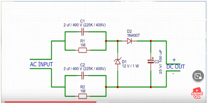
As you can see there output is coupled to mains side through two capacitors that pass the normal power supply operating current. If you connect either side of the DC output to ground, you will get enough current to shock you.
This is not isolated! The fact there is a capacitor in series between you and the main it means not that you can’t be electrocuted. Even through there is no direct galvanic connection because the capacitor includes an isolator between the conductors, but enough current still can flow through your body to earth to harm you if you touch the low voltage wire.
Sources and links to more information:
THE SHOCKING TRUTH ABOUT TRANSFORMERLESS POWER SUPPLIES
Power Supply Design Notes: Transformer-less power supply
What is Transformerless Power Supply & Its Working
14 Comments
Tomi Engdahl says:
220 Volt AC to 3v / 6v / 12v / 30v /60v / 90v / 120 / 150v / 190v DC LED Driver Without Transformer
https://www.youtube.com/watch?v=5ArDkROblxM
Tomi Engdahl says:
Tutorial: Electrical impedance made easy – Part 1
https://www.youtube.com/watch?v=tZBMfDvWF4U
Tutorial: Electrical impedance made easy – Part 2
https://www.youtube.com/watch?v=tZBMfDvWF4U
Tomi Engdahl says:
2W resistor burnout
https://www.youtube.com/watch?v=AjtYoYlXuSc
A 2 Watt carbon film resistor being overloaded with 27W for your viewing pleasure.
Viewer comments:
See? Resistance is futile!
It proves that everything is an LED if you’re brave enough
LERs- for when LEDs are just not cool anymore.
Nothing attracts views like a burning resistor. My Ohms Law video (on RCModelReviews) which features a burning resistor as the thumbnail has scored 1.6 million views
Tomi Engdahl says:
Non-Isolated AC/DC Buck Converters
https://www.renesas.com/eu/en/products/power-power-management/acdc-isolated-dcdc-converters/non-isolated-acdc-buck-converters
The Non-Isolated AC/DC Buck Converter family from Renesas is a series of universal input AC/DC switching buck regulators that feature a 700V integrated MOSFET capable of delivering up to 8W output power, with the output voltage as low as 3.3V, with variable package options. It features unique constant-off-time control method that helps to achieve ultra-low standby power, negligible EMI, and no audible noise. This product family also supports secondary-side-feedback isolated flyback topology.
Tomi Engdahl says:
the most dangerous power supply yet, Main power supply, but works good
https://www.youtube.com/watch?v=wClRBF1l69U
capcutapk says:
I’m glad to see that you’re discussing the pros and cons of transformerless power supplies. They’re definitely becoming more common, especially in inexpensive products
capcutapk says:
I’m glad to see that you’re discussing the pros and cons of transformerless power supplies. They’re definitely becoming more common, especially in inexpensive products.
https://capcuttemplatess.net/ says:
The shocking power supplies are a reminder of the importance of reliable CapCut Templates. Without them, unexpected power disruptions can lead to frustrating and costly consequences. Make sure to invest in quality templates to ensure a smooth and uninterrupted editing experience.
capcutmod says:
’m glad to see that you’re discussing the pros and cons of transformerless power supplies. They’re definitely becoming more common, especially in inexpensive products.
Tomi Engdahl says:
https://hackaday.com/2023/09/29/power-supplies-without-transformers/
Lessa says:
It’s good to see you talking about the upsides and downsides of transformer less power supplies. They’re becoming quite popular, especially in budget-friendly products.
Lessa says:
It’s good to see you talking about the upsides and downsides of transformer less power supplies. They’re becoming quite popular, especially in budget-friendly products.
Tomi Engdahl says:
https://hackaday.com/2025/02/24/line-power-with-no-transformer/
Tomi Engdahl says:
That output current is dangerous, if you touch any of the DC points you will receive a shock, that circuit is not isolated