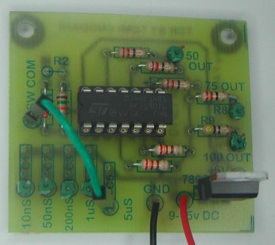
A time-domain reflectometer (TDR) is an electronic instrument that uses time-domain reflectometry to characterize and locate faults in metallic cables. I designed a TDR circuit many years ago for easy cable testing with oscilloscope:
That circuit was also turned to an electronics kit that is sold by Far Circuits.
When getting the original 74AC14 seemed to getting harder, I was thinking what would be a good high performance replacement (74HC14 works but the performance is not as good).
Few months ago got faster potential chip for my TDR circuit: PO74G14A from Potato Semiconductor has the same functionality as 74HC14/74AC14 (hex schmitt trigger) classic TTL logic but is designed to up to ~1GHz. I was hoping it will work on my TDR circuit without needing too much modifications to the circuit.
Some modifications are clearly needed because PO74G14A IC uses different voltage (1.65-3.6V vs typical 5V) and uses different case (SO14 vs DIP).
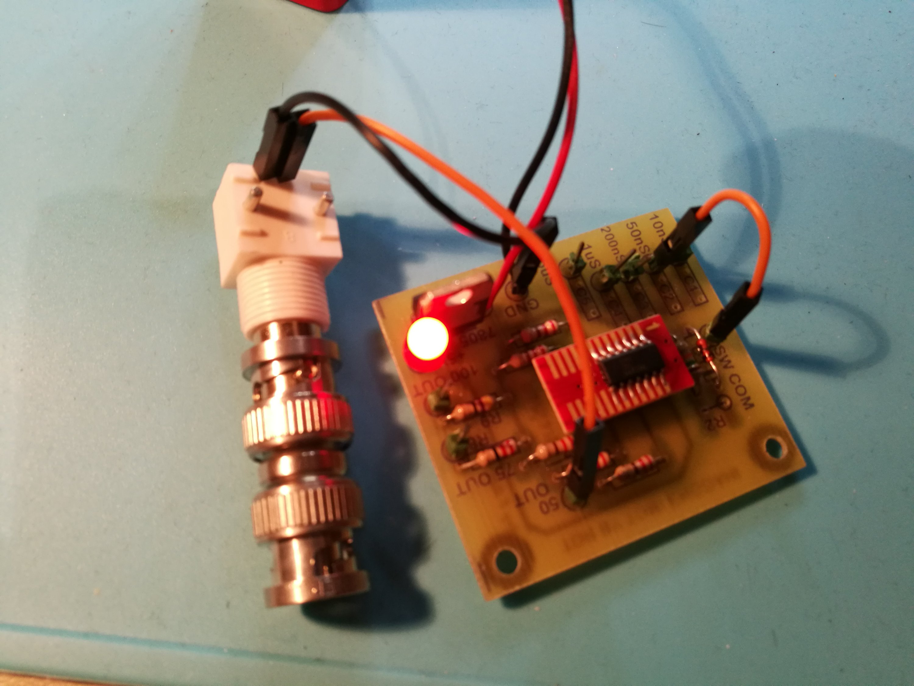
I used a chip adapter board from SO14 to DIP (thank to Polyteknikkojen Radiokerho OH2TI HAM club hackspace). That made it possible to connect the new chip to the original circuit boards IC socket. Hopefully things work OK, even though use of this kind of adapter on the circuit board not very well optimized for very high frequency signals are not optimal solution.
Had to make some quick changes to power supply because 3.3V used by chip. First I though of using 3.3V regulator on the place of original 7805. Instead of that as quick hack that needed less de-soldering/soldering and would be easier to undo, I just added one red led to take around 1.7V from 5V power source before chip gets it.
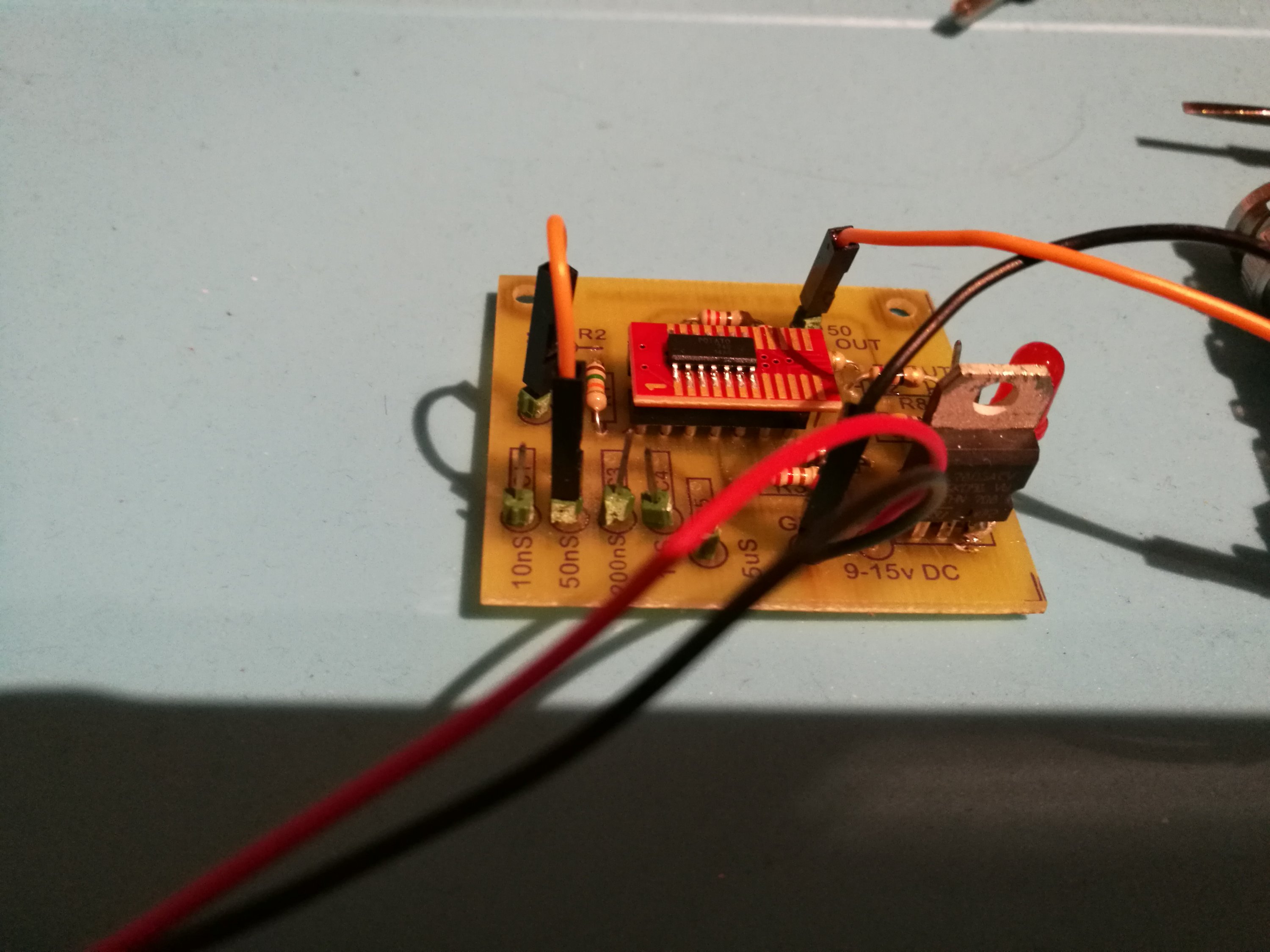
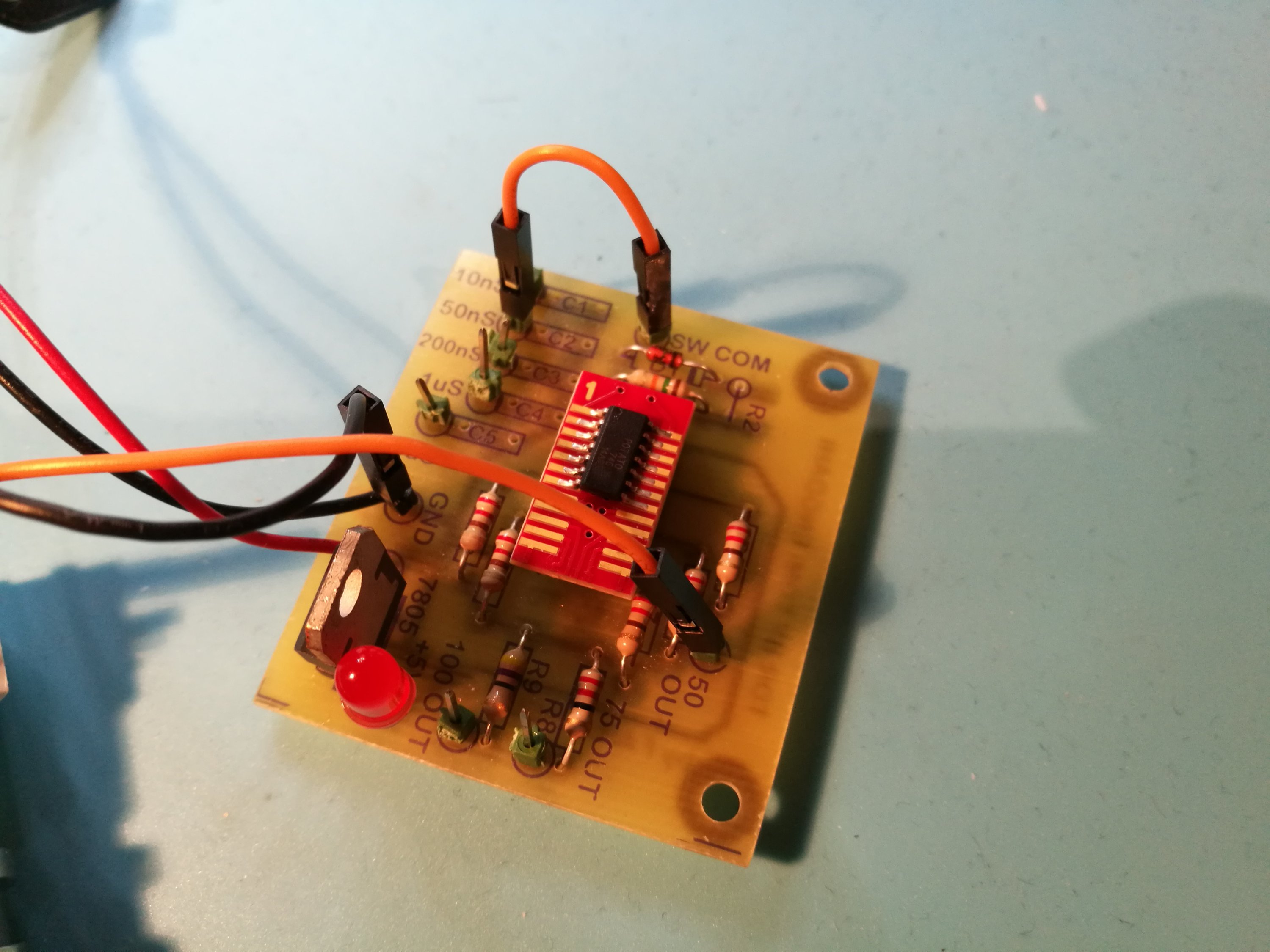
In use the LED works as power indicator that does not consume any extra power when circuit is powered from 9V battery (the power taken by LED would have been wasted on 3.3V regulator anyways).
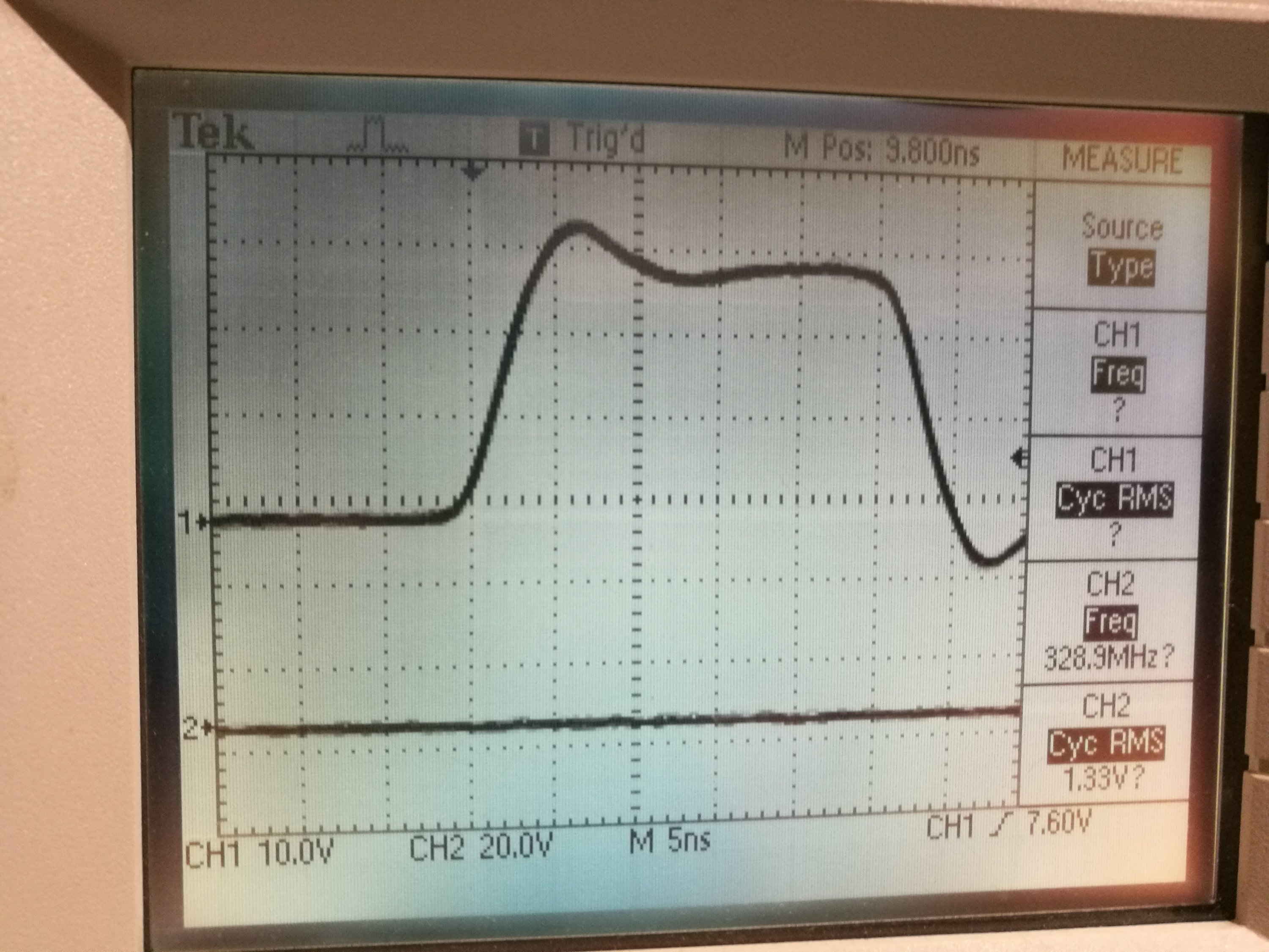
In the first attempt the circuit did not seem to be very stable. I made it more stable by adding one 100 nF ceramic capacitor between IC power and ground pins with very short wires. With this added component I got quite useful waveform on oscilloscope screen.
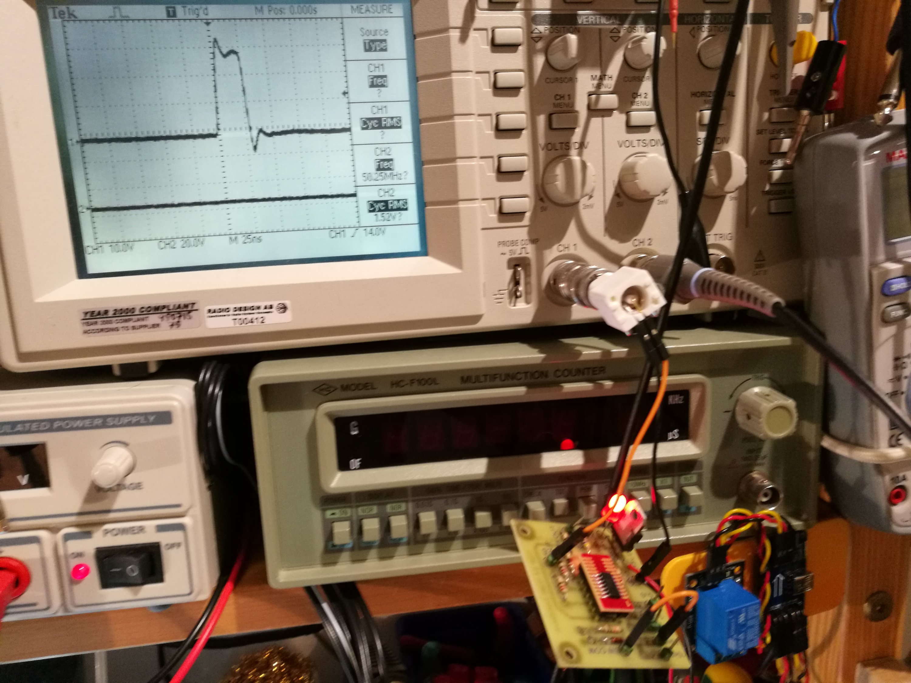
No termination on line gave some ringing reflections
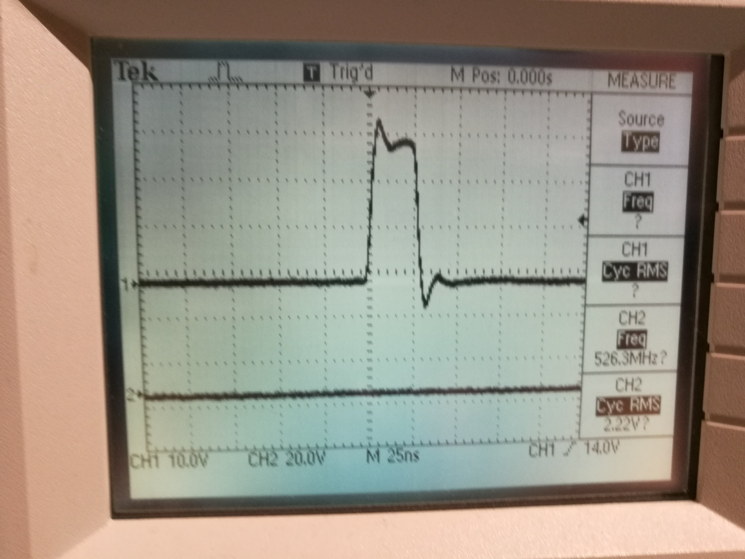
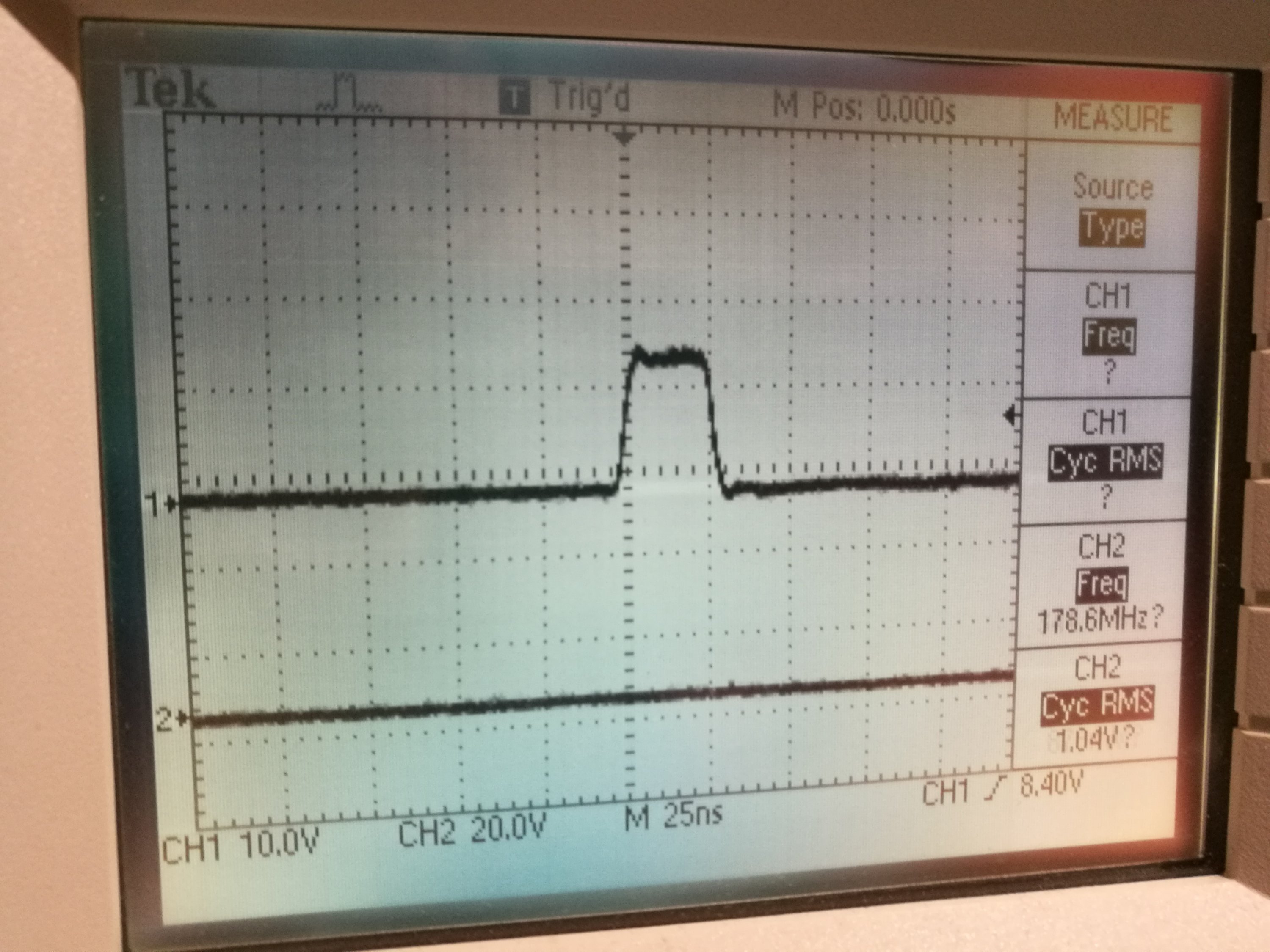
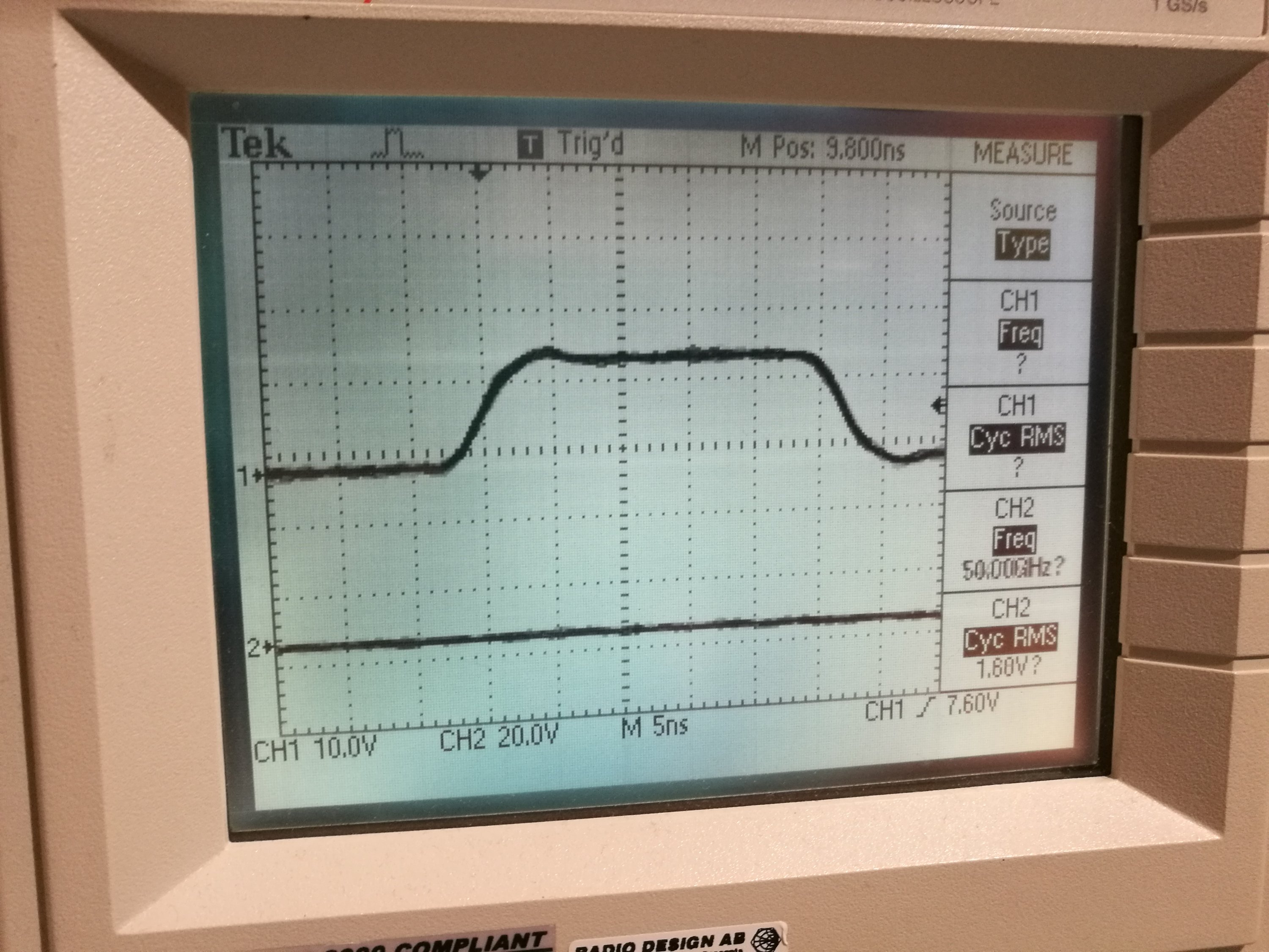
With 50 ohm termination the amplitude was reduced to half (which verifies 50 ohms circuit output impedance) and signal waveform looks nicer.
The idea works. Next it seems that I need maybe a more optimized power supply (3.3V regulator or 3V battery or something like that) and test the performance with faster oscilloscope (my 100 MHz scope has limited usability in this).
3 Comments
Tomi Engdahl says:
Here is somewhat related article and video using another hex inverter chip from Potato Semi to make an oscillator:
Afroman Makes A UHF Oscillator From A Potato
https://hackaday.com/2017/04/30/afroman-makes-a-uhf-oscillator-from-a-potato/#more-255050
Using one of their 74GU04 parts, he made a ring oscillator relying only on the stray capacitances of its gate inputs for its timing, and while he didn’t manage to achieve a GHz he did measure it at about 373 MHz. He took a look with a spectrum analyser, and as you might expect from a logic circuit found strong harmonics in the GHz range.
Fun with 1.1GHz Potato chips
https://www.youtube.com/watch?v=8rRRvgjLjZU
I built a ring oscillator using a 1.125GHz 74 series logic inverter IC from Potato Semiconductor. It was fun.
Tomi Engdahl says:
https://www.reddit.com/r/electronics/comments/688v3m/potato_semiconductor_you_could_call_the_potato/
Tomi Engdahl says:
TDR with different Oscilloscopes.
https://www.youtube.com/watch?v=nHHWYYZdN0A
Trying the TDR ( Time Domain Reflectometer ) with different oscilloscopes. First, the old Tektronix 547 shows it’s stuff, then the TDS220 oscilloscope, soon after.