Ground loop can cause considerable currents to flow on all cables on the loop. It is not uncommon to have a voltage of 1V RMS between the earth connections of power outlets that are wired separately back to the switchboard. This small voltage, with a total resistance of perhaps 0.2-0.5 Ohm, will cause a loop current of 2 to 5 Amps, all of which flows in the shield of the interconnect. This is sufficient to cause a voltage difference across the interconnect, which the amplifier cannot differentiate from the wanted signal. An earth loop will typically inject either a 50Hz or 60Hz hum into the signal.
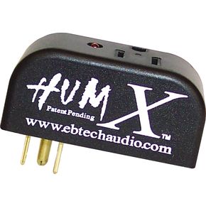
You might have seen the following kind of device marketed for ground loop problem solving for USA markets:

The product page boasts with the following features: The Hum X Exterminator removes unwanted voltage and current in the ground line that cause ground loop hum. This noise reduction adapter simultaneously maintains a solid, safe ground. You no longer have to run your audio signal through filtering that results in loss of volume, tone, or both. Some devices simply remove or float the ground, which is never safe! Hum X removes the ground loop while leaving the ground and your signal intact. Easy to use and completely effective!
The question what comes to my mind when I saw this is how this thing works. Harmony Central Ebtech Hum-X Review gives some interesting details how this device is expected to work:
After briefly analyzing the input to output ground connections I found this to be very similar to a galvanic isolator that is widely used in the boating communities for ship to shore power connections. It appears that there are two diodes and a 1Kohm impedance that are connected in parallel from input ground to output ground. The parallel diodes are configured back to back so that there is a 0.7volt drop in each direction. Since I could not look inside the unit the diodes are an assumption on my part? they may have used transistors configured as diodes. The potential safety hazard here, is that one or both of these diodes could fail open leaving the user with no safety ground.
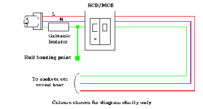
Non-isolating isolator article gives information how those boat isolators work: When a boat plugs into shorepower, the shorepower cord will often make an electrical connection between the underwater metals on all the boats that are plugged in, creating a risk of galvanic corrosion. A galvanic isolator is designed to prevent this by blocking DC currents with voltages that reach as much as -1.2 volts DC. This is achieved by installing two sets of devices known as ‘diodes’, with one set installed in the opposite direction to the other. There are two types of galvanic isolator, one with a device known as a ‘capacitor’ wired around the diodes, and one without. Without a capacitor, if there is AC leakage on the shorepower ground circuit that has a voltage above 1.2 volts AC, this AC leakage will ‘bias’ the diodes into a conductive state.
Narrowboat AC Electrical systems article give the following application example for boat galvanic isolator use:

When the isolator is used for galvanic corrosion protection we want to block the DC and let the AC pass though, so the quite large capacitor in parallel with the diodes is a good idea. On audio systems ground loop protection we want to block low voltage AC, so the version without capacitor is the right one to use (there could be some very small capacitors used on audio isolators for RF protection and sometimes resistors to pass low leakage currents in case installed to system where there is no ground loop).
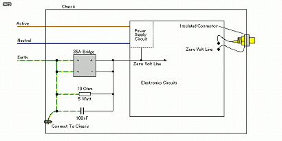
Elliott Sound Products article Earthing Your Hi-Fi – Tricks and Techniques article give some construction details how A High Current Safety Loop Breaker Circuit (pretty similar to one believed to be inside HumX) could be built:

This circuit example has the ground isolator between the mains power ground and audio part zero voltage line. Here the circuit the current loop breaking the loop is done with the 10 Ohm resistor, the current is now less than 200mA, and the voltage across the interconnect will be very much smaller, reducing the hum to the point where it should no longer be audible. This is how the circuits work when the potential difference over the 10 ohm resistor is lower than the voltage drop of the diodes on the rectifier bridge (around 1.2-1.4V). The capacitor will pass high frequencies (RFI protection).
In case there are is some serious ground leakage the diodes will start to conduct and pass through enough current needed to burn the mains fuse if needed without too much vooltage drop (no dangerous voltages over the isolator circuit). In the event of a major fault, one (or more) of the diodes in the bridge will possibly fail. Semiconductors (nearly) always fail as short circuit, and only become open circuited if the fault current continues and ‘blows’ the interconnecting wires. High current bridge rectifiers have very solid conductors throughout, and open circuit diodes are very rare. Use of the bridge means that there are two diodes in parallel for fault current of either polarity, so the likelihood of failure (to protect) is very small indeed.
If you plan to do any experimenting in this field, make sure that you find out the legal requirements in your country, and don’t do anything that places you at risk – either from electrocution or legal liability. Neither is likely to be a pleasant experience.
Electrical safety cannot be over emphasised. Hum is damn annoying, and everyone wants it gone. There is no good reason to sacrifice one for the other, since safety and hum-free operation can peacefully co-exist with care and the right techniques.

NEVER use a three prong to two prong AC adapter to fix a ground loop problem. These devices are meant to provide a safety ground (via the cover plate screw to a grounded outlet) in the event a three prong plug is used with a two prong outlet in USA. It is wrong and dangerous trying to use such adapter to break the safety ground connection. Also do not try to use any other adapter that breaks the ground connection (some travel adapters).
66 Comments
Tomi Engdahl says:
https://www.biltema.fi/veneily/veneen-sahkojarjestelma/asennustarvikkeet/galvaaninen-eriste-zink-saver-2000024139
Tomi Engdahl says:
Earth Terminal Voltage Drop TN-C-S
https://www.youtube.com/watch?v=iozyjrPmY7U
How the earth terminal on a TN-C-S supply can be at a different voltage to the true Earth.
As the neutral and earth conductor are combined outside the installation, current in the neutral causes a voltage drop, which results in the earth terminal having a different potential (voltage) to the true Earth outside.
Tomi Engdahl says:
Boating Transformers – Technical Notes
https://airlinktransformers.com/post/boating-transformers-technical-notes
standard waterproof transformers to eliminate the risk of galvanic corrosion between your boat’s hull and other boats or metal objects
Tomi Engdahl says:
Earthing the DC ground does not cause hum. A well-designed grounding scheme is both safe and hum-free. Hum enters the picture when the constructor assumes all earth are equal, then discovers that there are small (audible) rectification currents entering the audio path from differences between the various ground points they have used. Grounds should all terminate at one point – known as “star”.
This article by Rod Elliot shows its use in more detail and provides a few more tips – including the use of a “star” ground point: https://sound-au.com/earthing.htm
Tomi Engdahl says:
GND control.
Take out speaker hum.
https://ifi-audio.com/products/gnd-defender/
AI ground detection.
With a GND Defender at the IEC power input, it will intelligently detect and remove the ground loop at the component.
Behind this, the GND Defender:
Intelligently breaks DC ground loops to eliminate ground loop hum
EMI shielding is retained
Equipment Safety is unaffected (not a ground lift – so maintains equipment safety ground)
If multiple ground loops exist, more than one GND Defender may be required.
The GND Defender is smarter than the average ground lift. By a long way.
Battleship build.
The GND Defender is not only at the cutting-edge in terms of technology but also safety:
High-performance glass passivated semiconductor
High Case Dielectric Strength of 1500VRMS UL Listed
X7R Capacitor
High-temperature stability
Flame resistant IEC socket/connector/chassis
Fireproof polymers UL94-V0
Remember that best practice is to always keep at least one direct power cable connection.
Surge overload rating of 220A. With a maximum rating >10A, continuous current rating 7A, it handles all voltages around the world from 90-240V.
Tomi Engdahl says:
https://www.facebook.com/groups/DIYAudio/permalink/6530697376996053/
It is possible to use a galvanic isolator, which in essence is two or three diodes in series, with a parallel set pointing the other direction. This will lift the equipment ground up by a couple of volts, and potentially raise the reference out of any noisy ground. While maintaining AC conductivity. They are used on boat shore supply’s to reduce galvanic corrosion when hooked up to shore mains supply. The diodes are special ‘safety, fail short’ AYBC approved components.
finally someone with a solution rather than the cannot do replies we usually see… or read a book type dismissive replies. Jon, for sure we need more of you!
, thankyou, here is a link to one for reference. https://sterling-power.com/products/zinc-savers-galvanic-isolators
Tomi Engdahl says:
It’s quite simple; it just puts a pair of anti- parallel silicon diodes in the ground lead connection. Silicon diodes only switch on when the applied voltage exceeds about 0.6 Volts. So small AC signals responsible for audio hum can’t get past the diodes, but if you get a short between the live wire and ground, that will still be passed by the diodes, blowing the fuse or tripping the circuit breaker.
So it has the same effect on the audio as removing the ground connection, but still retains the safety of a grounded appliance.
Tomi Engdahl says:
If you then have a fault and a large ground current flows, it could easily take out the diodes, and if they blow before the fuse or breaker, you would end up with a potentiaaly lethal high voltage on the equipment as the ground had effectively been disconnected.
Tomi Engdahl says:
may do… I prefer to fix the real cause of the ground loop by correcting the grounding system and by using isolators in the signal path, rather than potentially compromising the protective earth.
Tomi Engdahl says:
Greer Kemp I’m surprised that Audiophools haven’t taken on board the “Technical Ground” approach that was widely used in Analog TV studios. The AC power for the signal pricessing was run through an isolation transformer, and the ground was an actual stake driven into the actual ground. You could even get special high-conductivity cement, so you’d drill something like a 3″ hole, fill it with the cement, and put the grounding rod into it.
I mean, the lift in audio verisimilitude and musicality was staggering, to anybody with ears capable of hearing it, that is
Tomi Engdahl says:
Fix the pin 1 problem and you won’t need a half-ass gimmick.
https://www.prosoundweb.com/the-pin-1-problem-revisited/
Tomi Engdahl says:
https://www.hifihuone.fi/tuotteet/kaapelit/virtapuhdistimet-ja-jakoblokit/ifi-gnd-defender/
Tomi Engdahl says:
https://huggingface.co/blog/static-embeddings