A class-D amplifier or switching amplifier is an electronic amplifier where all power devices (usually MOSFETs) are operated as binary switches. They are either fully on or fully off. The term “class D” is sometimes misunderstood as meaning a “digital” amplifier. While some class D amps may indeed be controlled by digital circuits, the class D amplifier control circuit can be also implemented with analogue component. I would rather call class-D amplifier as a switching amplifier rather than “digital amplifier”.
Class D amplifiers work by generating a square wave of which the low-frequency portion of the spectrum is essentially the wanted output signal. In a simplest form he generated signal can be just pulse-width-modulated (PWM) square wave, but in many practical class D amplifiers the output signal is slightly more complicated. After the output driver stage a passive low-pass filter removes the unwanted high-frequency components, i.e., smoothes the pulses out and recovers the desired low-frequency signal. To maintain high efficiency, the filter is made with purely reactive components (inductors and capacitors). The switching frequency is typically chosen to be ten or more times the highest frequency of interest in the input signal. This eases the requirements placed on the output filter. In cost sensitive applications the output filter is sometimes omitted.
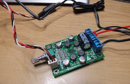
I bought some time ago Y148 Audio Amplifier Module so learn more than just the theory of the class D amplifiers. Hands on on some new technology gives better insight than just reading the theory. Here is the picture of the amplifier module ready to use on my desk.
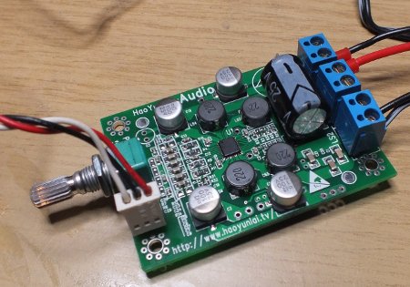
To make connecting the wires easier I have added screw terminals to Y148 Audio Amplifier Module (the module came only with soldering holes for power and speaker connections). Speaker and power connections have large well spaced holes. I also added pin strip (L_in, GND, R_in) for audio input and audio cable to connect the audio source.
Here is some data of the amplifier:
- Model: Y148
- PCB board
- Adopts YDA148 high-efficiency digital audio power amplifier IC
- DC input voltage: 9~15V
- Current: 2~4.5A
- Power output at DC 15V input: 15W x 2 (8 ohm), 30W x 2 (4 ohm)
- Power output at DC 12V input: 10W x 2 (8 ohm), 20W x 2 (4 ohm)
- Needs heat sink at 4 ohm, doesn’t need heat sink at 8 ohm
- Frequency response: 10Hz~20KHz(+/-0.2dB @1KHz)
- Load speaker: 4 / 6 / 8 ohm
- SNR: at least 90dB
- Harmonic distortion: THD+NC no more than 0.1%P=0.1W
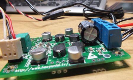
Y148 Audio Amplifier Module is cheap super small amplifier. It works great, and plays all right. No noticeable noise/distortion at reasonable audio levels. It runs nicely on 12V power. Great product, especially the price is really attractive.
The specifications are pretty good for such small device. The module drives 8 ohms speakers from 12V power source directly. The tiny IC in the center of the circuit board can handle 2x10W without any heatsink! If you try to run 4 ohm speakers or higher power the chip gets quite hot (you should be able to solve the problem with a suitable small heatsink added on top of that that little chip).
You can use it even on battery powered applications, because you can get quite a bit of audio output with about 100mA from the battery! Not the full power but useable volume levels. The high efficiency is the reason that class D amplifiers are popular in many battery powered electronics devices.
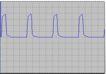
As I told earlier Class D amplifiers work by generating a square wave of which the low-frequency portion of the spectrum is essentially the wanted output signal. YDA148 high-efficiency digital audio power amplifier IC operates around 500 kHz frequency according to datasheet (I measured 508 kHz on my module). The IC generates pulses (starting from 0V and going up to +12V in level) to both + and – side of speaker output line at that frequency. The pulse length varies depending on the signal that needs to be sent to speaker. When there is no output signal, both pulses are short. When the amplifier needs to send positive voltage to speaker, the pulse at + line gets longer and longer depending how high voltage need to be set to speaker. The – side pulses stay at the same short length. In case of negative voltage needs to be sent to speaker, the – side pulses get longer and + side stays short. The picture below show the pulses that can be seen on speaker + output on IC output.
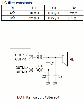
YDA148 high-efficiency digital audio power amplifier IC datasheet says that a low pass filter at corner frequency of 50 kHz normally needed (digital amplifier operates around 500 kHz).
The amplifier board has this kind of filter in it. Ther filter works pretty well in attenuating the high frequency signal. I measured around 50 mV (RMS) 508 kHz triangle wave on the speaker oputput after the filter. So the switching feququency is pretty well attenuated, and in taking account the fact that speaker elements can’t play back those high fequencies and will not hear them, I don’t think it could hurt the the sound quality at all.
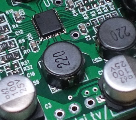
The size of components is one that might in some applications drive to try to avoid the filters. As you can see on the board I have the filter components take much more board space than the actual IC. In the picture below you see the amplifier IC on the top and filter components for one channel on the bottom.
Direct connection from IC to speaker element is also possible according to YDA148 datasheet when speaker has element is suitable (inductance 20 microhenries or more), wires are short and speaker is present always. I think that direct connection method would be feasible only in active speaker applications where amplifier and speaker elements are inside same cabinet. In all other applications that filter is needed, because EMC reasons (feeding a strong 500 kHz signal to unshielded speaker cable generates easily lots of interference).
YDA148 datasheet also says that this IC supports differential input. Using differential interfaces is a good idea in many audio applications. Unfortunately this amplifier module board does not support using differential input. The module I have has only traditional unbalanced line level input option. That is useable, but I would have preferred to have differential interface as an option.
Y148 Audio Amplifier Module seems to be a good small audio amplifier. It was cheap, performed well and provided a good platform to lears about class D amplifiers. Class D amplifier technilogy is nowdays mature and ready to be taken into use.
69 Comments
Tomi Engdahl says:
555 Class D Power Amplifier [130144-I]
https://www.elektormagazine.com/labs/555-class-d-power-amplifier-130144-i
With this project, I like to build a small class D amplifier based on a 555 timer IC. I also like to use only “common” components, so this project has great educational value and is easy to build.My goal is to produce about 5W RMS power into 4ohm. Distortion level should be less than 1%.Circuit description VERSION1 (see circuit diagram below)
Tomi Engdahl says:
https://everycircuit.com/circuit/5572159154421760/class-d-amplifier
Tomi Engdahl says:
https://www.peculiar-games.com/electronics/555-class-d-amplifier
Tomi Engdahl says:
https://www.headphonesty.com/2025/10/why-audiophiles-dont-trust-class-d-amps/?fbclid=IwVERDUANbDNVleHRuA2FlbQIxMAABHhRqDAK7GDMA4E3fhJKTNbG1jYTtQ5h9aJlREqNHMu509ZDy1QHM84kmgLCx_aem_KvfJ67-51qVj1rKuHVnM1w#6_They_Dont_Look_or_Feel_Like_Serious_Gear
Tomi Engdahl says:
https://sound-au.com/articles/class-d2.htm
Tomi Engdahl says:
https://www.analog.com/en/resources/technical-articles/fundamentals-of-class-d-amplifiers.html
Tomi Engdahl says:
https://www.headphonesty.com/2025/10/why-audiophiles-dont-trust-class-d-amps/
Tomi Engdahl says:
A class-D amplifier, or switching amplifier, is an electronic amplifier in which the amplifying devices (transistors, usually MOSFETs) operate as electronic switches, and not as linear gain devices as in other amplifiers. They operate by rapidly switching back and forth between the supply rails, using pulse-width modulation, pulse-density modulation, or related techniques to produce a pulse train output. A simple low-pass filter may be used to attenuate their high-frequency content to provide analog output current and voltage.
https://en.wikipedia.org/wiki/Class-D_amplifier
Tomi Engdahl says:
Support for is digital claim: The controlling of the switching of the output controlling switching devices is digital (0 or 1) operation.
For claim not digital: very many current class D amplifiers take analog signal in and do most processing using analog techniques before driving output switches with digital signal.
It is possible to make class D amplifiers that does all signal handling digital from digital audio input signal to DSP that drives output switching devices. After that there is analog LC low pass filter before going to speaker (some designs built into speakers can get away without LC low pass filter)
A class-D amplifier, or switching amplifier, is an electronic amplifier in which the amplifying devices (transistors, usually MOSFETs) operate as electronic switches, and not as linear gain devices as in other amplifiers. They operate by rapidly switching back and forth between the supply rails, using pulse-width modulation, pulse-density modulation, or related techniques to produce a pulse train output. A simple low-pass filter may be used to attenuate their high-frequency content to provide analog output current and voltage.
https://en.wikipedia.org/wiki/Class-D_amplifier
Tomi Engdahl says:
https://www.elprocus.com/class-d-amplifier-operation-applications/
Tomi Engdahl says:
https://en.wikipedia.org/wiki/Class-D_amplifier
Tomi Engdahl says:
https://www.audiosciencereview.com/forum/index.php?threads/class-d-amplifier-with-digital-inputs.22009/
Tomi Engdahl says:
theory it could have a number of tangible benefits, right?
1. Lower Total Harmonic Distortion
2. Increased Dynamic Range
3. Better Signal-to-Noise Ratio
4. Reduced Power Consumption
5. Compact and Lightweight Designs
I’m not an engineer so just guesses but I’ve now talked myself into being excited for the next wave of Class D using GaN components.
I suspect that class D by itself will be sufficient for the majority of listeners.
Audiophiles may want their class D amplifier designs mixed with class A to provide the distortion and sweetness that they want. A few companies do this.
It will be interesting to see if class H and class G amplifier designs are used more in the future.
Class D if done well is not going to be the weak link for any system (That is room or transducers), but there are a lot of ways to do it poorly.
Class G/H are not a clear win once you are running class D, but are a long standing and well tested technology in older power amplifiers at live event scale.
https://www.reddit.com/r/audiophile/comments/1e2cmhp/is_classd_technology_about_as_good_as_itll_ever/
Tomi Engdahl says:
“Class D” has nothing to do with digital it has everything to do with the drive transistors bias curve – while it is the most binary of the amplification methods, its still an analog signal.
https://www.facebook.com/share/p/1SPpfk2VmM/
Tomi Engdahl says:
A fully digital Class D DSP is an integrated audio amplifier that processes signals in the digital domain, including the conversion of digital input to the switching signals of a Class D amplifier, bypassing the traditional digital-to-analog converter (DAC) stage for a more efficient and simplified solution. These devices combine digital signal processing (DSP), power amplification (Class D)
Tomi Engdahl says:
https://www.analog.com/en/resources/analog-dialogue/articles/class-d-audio-amplifiers.html
https://www.diyaudio.com/community/threads/difference-betweeen-class-d-and-digital-amplifiers.56709/
Tomi Engdahl says:
https://www.reddit.com/r/audiophile/comments/1e2cmhp/is_classd_technology_about_as_good_as_itll_ever/
Tomi Engdahl says:
Sinclair X-10
https://rk.nvg.ntnu.no/sinclair/audio/x-10.htm
https://www.audiosciencereview.com/forum/index.php?threads/class-d-pwm-amplifier-archaeology.37017/
https://www.diyaudio.com/community/threads/sinclair-x10-x20.74064/
https://www.vintage-radio.net/forum/showthread.php?t=81139
Tomi Engdahl says:
Even the engineers who built Class-A legends are admitting the hierarchy has changed.
Full story: https://www.headphonesty.com/2025/11/class-d-crushes-class-a-independent-tests/