A network analyzer is an instrument that measures the network parameters of electrical networks. Today, network analyzers commonly measure s–parameters. Full featured network analyzers are expensive instruments, and sometimes a simpler. Scalar Network Analyzer (SNA) is a simpler form of RF network analyzer that only measures the amplitude properties of the device under test. SNA is very useful for measuring the amplitude response of a variety of components. The scalar network analyzer is a popular instrument used for measuring scalar stimulus-response. Manufacturers frequently perform scalar stimulus-response measurements (also known as scalar network analysis) to measure the gain, insertion loss, frequency response or return loss of devices such as cables, filters, amplifiers and complex systems encompassing multiple components. Effectively, a scalar network analyzer, SNA, works just as a spectrum analyzer in combination with a tracking generator.
It is also possible to build scalar network analyzer in several ways. One option to build simple SNA is to have suitable adjustable RF generator and simple RF amplitude detector (instead of full spectrum analyzer). I have done some testing with ad9850 dds module and I had already built simple RF amplitude detector, so all I had to combine them and write some software to make my own simple SNA.
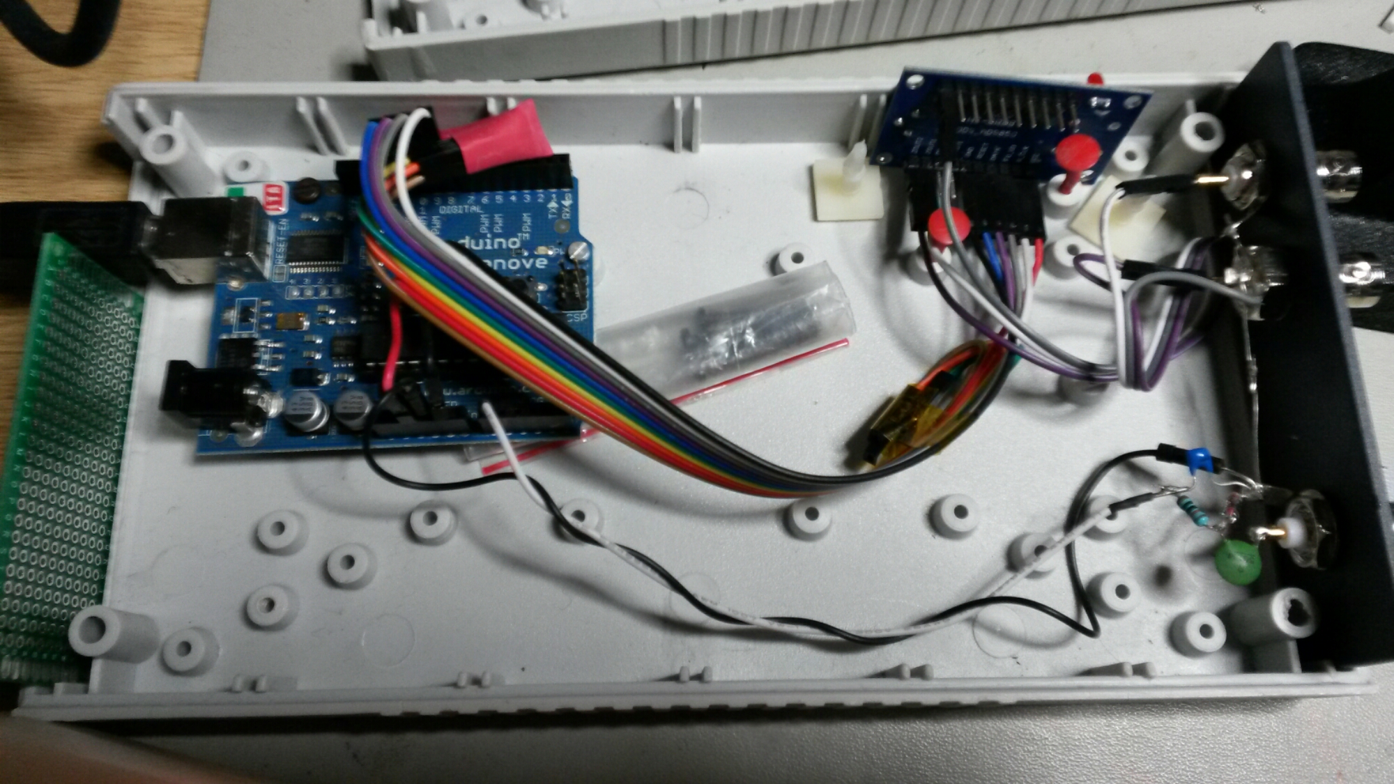
The signal flow on in the system is like this:
USB -> Arduino -> AD9850 -> DUT -> RF probe rectifier -> Arduino Analog in -> USB
For RF detection Ibased my design on simple RF probe idea as from Designing RF Probes page:
I decided to make a slight modification of the circuit more optimized for me. To get suitable value for R1 I used LC filter calculator. I decided that R1 = 10 kohms would give OK results. I used AA113 germanium diode, because I had several of them. So I ended up with the following RF detector circuit:
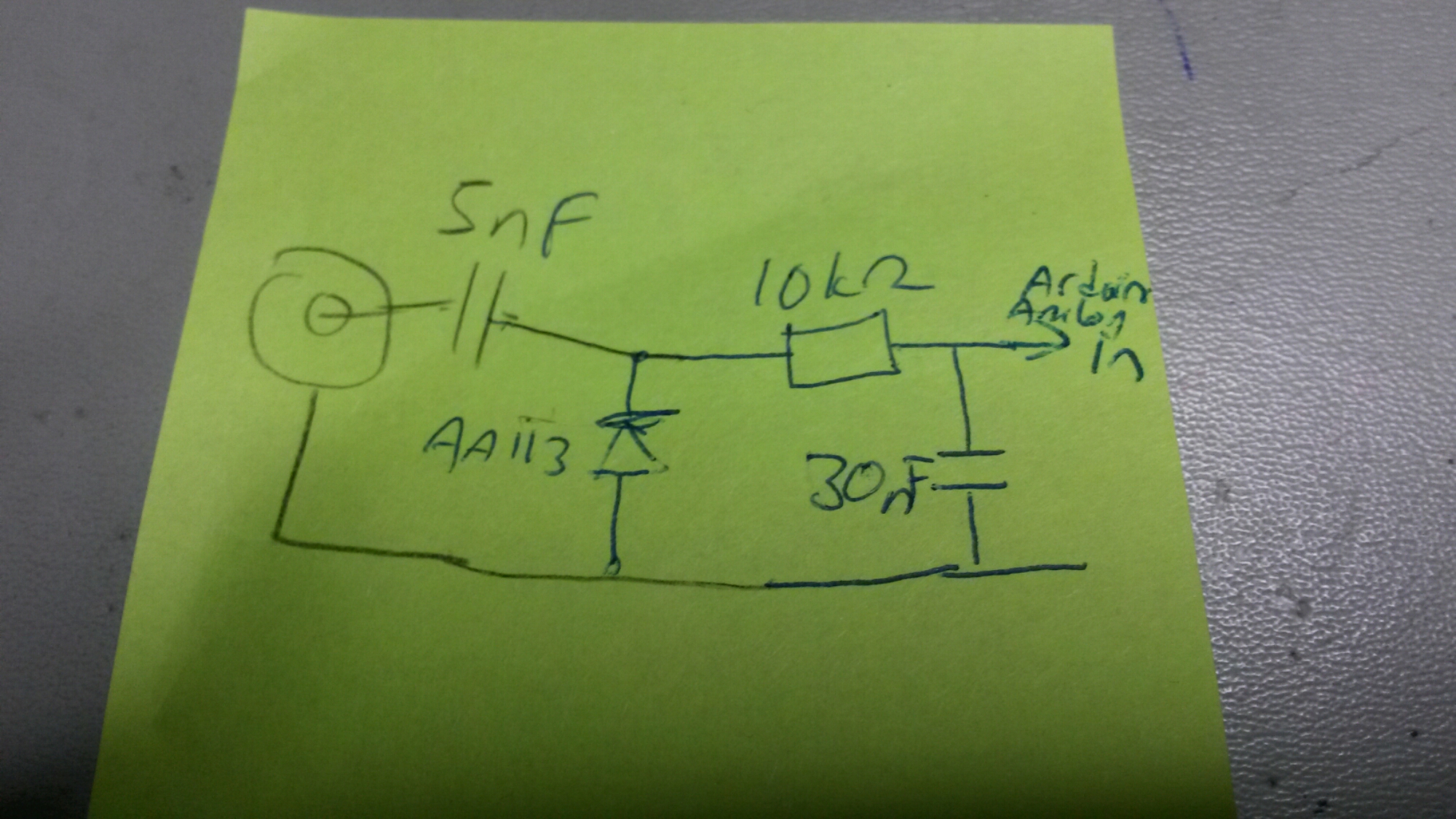
I connected the output to Arduino analog in 0.
I set the analog reference to 1.1 internal reference to get suitable measurement range
I modified the AD9850 useful test sketch for Arduino(-s) source code so that I have a new test command: “m” command – measurement sweep from frequency to frequency at given step size – it prints out frequency (in kHz) and analog measurement value (AD converter value). The command takes three arguments: start frequency, end frequency and step size. So example for command to give on command line would be
m 1000 100000 1000
When used it will print out two number per line: freqency in kHz and AD converter measurement value (value range 0-1023).
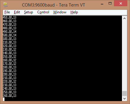
m 100 100000 200
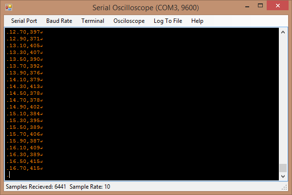
Now I can get data, but a visual output would be nice (something easier than cut&paste the data to Excel and draw chart). So I started looking for some program I could use and not have to write my own for this. After some searching I saw Serial Oscilloscope (with Arduino) video that showed how to use Serial oscilloscope software to plot data from Arduino.
Serial oscilloscope is a Windows application that plots comma-separated variables within any incoming serial steam as channels on a real-time oscilloscope. The application also functions as a basic serial terminal, received bytes are printed to the terminal and typed characters are transmitted. Serial Oscilloscope is compatible with any serial stream containing comma-separated values terminated by a new-line character (“\r”). This was exactly right for my nest visualization tests.
Console:
Scope view
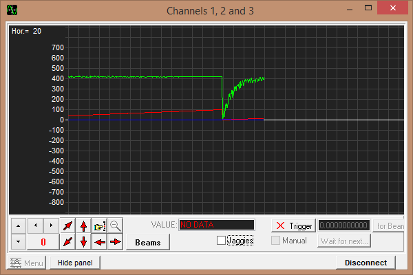
Now I can get a plot-out of the measure circuit frequency response (output vs frequency). This is a good start for experimenting and already useful. AD9850 module can generate frequencies in 0-40 MHz frequency range.
There are still some issues until this is a real useful SNA. For example there would be some need for some impedance matching, because now the generator output is 100 ohms and RF input is high impedance. Ideally those should be 50 ohms for most RF measurements. Also a directional coupler would be nice to have… This is just a start of the project.
Here is my modified version of AD9850 useful test sketch for Arduino(-s) source with new “m” command:
The modified source code:
/*
Simple controller for AD9850 modules
Uses serial protocol (refer to AD9850 datasheet what pins need to be pulled up/down
Uses library by Elecfreaks http://elecfreaks.com/store/download/datasheet/breakout/DDS/EF_AD9850_library.zip
(for use with chipkit delete that unnecessary line “#include <avr/pgmspace.h>” from .h file)
Fix the pin numbers used to communicate with module
Serial comms – 9600, NewLine (0x0A) denotes end of input,
f 10000 – set frequency
s 20 20000 10 1000 – sweep from frequency to frequency using this step size in that many milliseconds
o 10 10000 5 3000 – oscillating sweep from frequency to frequency and back using this step size in that many ms
m 1000 100000 1000 – measurement sweep from frequency to frequency at given step size
NB! no error checking in input, code relies on intelligence of user
*/
#include <EF_AD9850.h>
#define MAXBUF 40
// FIXME set up pins to match your case
// parameters in following order – CLK, FQUP, RESET, DATA
// EF_AD9850 AD9850(11, 10, 8, 9);
EF_AD9850 AD9850(8, 9, 11, 10);
double freqValue = 0;
double freqStart = 0;
double freqEnd = 0;
double freqStep = 0;
int sweepDelay = 0;
char freqStr[MAXBUF];
int bufPos = 0;
char byteIn = 0;
int mode = 0;
int meas =0;
char *fEnd1, *fEnd2;
void setup()
{
AD9850.init();
AD9850.reset();
Serial.begin(9600);
memset(freqStr,0,sizeof(freqStr));
analogReference(INTERNAL);
}
void loop()
{
if (mode == 1 || mode == 2)
{
if (((freqStep > 0.0) && (freqValue + freqStep <= max(freqStart,freqEnd))) || ((freqStep < 0.0) && (freqValue + freqStep >= min(freqStart,freqEnd))))
freqValue += freqStep;
else
if (mode == 1)
freqValue = freqStart;
else
{
freqStep *= -1;
freqValue += freqStep;
}
AD9850.wr_serial(0,freqValue);
delay(sweepDelay);
if (meas == 1)
{
Serial.print(freqValue/1000);
Serial.print(‘,’);
Serial.println(analogRead(0));
}
}
while (Serial.available())
{
byteIn = Serial.read();
if (bufPos < sizeof(freqStr))
freqStr[bufPos++] = byteIn;
else
{
bufPos = 0;
byteIn = 0;
memset(freqStr,0,sizeof(freqStr));
Serial.println(“Command too long. Ignored.”);
}
}
if ((byteIn == 0x0a) or (byteIn == 13))
{
switch (freqStr[0])
{
case ‘f’:
mode = 0;
freqValue = strtod(freqStr+2,NULL);
freqEnd = 0;
freqStep = 0;
sweepDelay = 0;
Serial.print(“Frequency “);
Serial.println(freqValue);
break;
case ‘s’:
case ‘o’:
freqStart = abs(strtod(freqStr+2,&fEnd1));
freqEnd = abs(strtod(fEnd1,&fEnd2));
freqStep = abs(strtod(fEnd2,&fEnd1));
if (freqStep == 0)
{
Serial.println(“You gotta be kidding me, step can not be 0″);
break;
}
sweepDelay = abs(atoi(fEnd1));
if (freqStr[0] == ‘s’)
{
mode = 1;
Serial.print(“Sweep”);
}
else
{
mode = 2;
Serial.print(“Oscillate sweep”);
}
Serial.print(” start freq. “);
Serial.print(freqStart);
Serial.print(” end freq. “);
Serial.print(freqEnd);
Serial.print(” step “);
Serial.print(freqStep);
Serial.print(” time “);
Serial.println(sweepDelay);
sweepDelay /= abs(freqEnd – freqStart) / freqStep;
if (mode == 2)
sweepDelay /= 2;
if (freqStart > freqEnd)
freqStep *= -1;
freqValue = freqStart;
break;
case ‘m’:
freqStart = abs(strtod(freqStr+2,&fEnd1));
freqEnd = abs(strtod(fEnd1,&fEnd2));
freqStep = abs(strtod(fEnd2,&fEnd1));
if (freqStep == 0)
{
Serial.println(“You gotta be kidding me, step can not be 0″);
break;
}
mode = 1;
meas = 1;
sweepDelay = 100;
freqValue = freqStart;
break;
default:
Serial.println(“AI blown up – unknown command”);
}
memset(freqStr,0,sizeof(freqStr));
byteIn = 0;
bufPos = 0;
AD9850.wr_serial(0,freqValue);
}
}
20 Comments
Tomi Engdahl says:
Someone seems to have developed this kind of idea more:
$40 Antenna Analyzer with Arduino and AD9850
http://hackaday.com/2015/08/06/40-antenna-analyzer-with-arduino-and-ad9850/
If you are a hacker, you might consider ham radio operators as innovative. Most people, however, just see them as cheap. So it is no surprise that hams like [jmharvey] will build an antenna analyzer from a DDS module and an Arduino instead of dropping a few hundred dollars on a commercial unit. As he points out, you probably only need an analyzer for a day or two while you set up an antenna. Unless you are a big time antenna builder, the unit will then sit idle on the shelf (or will wind up on loan to hams even cheaper than you are).
DDS_AD9850_AntennaAnalyzer
https://github.com/jmharvey1/DDS_AD9850_AntennaAnalyzer
This is a no frills DIY Analyzer intended for frequencies ranging from 1.6 to 30 Mhz See http://youtu.be/C6YxD72sX_Y for a description of this project
Tomi Engdahl says:
There seems to be some ready made analyzers on the market using similar signal generator:
SARK100 Mini HF ANT SWR Antenna Analyzer For Ham Radio Hobbists
http://www.banggood.com/SARK100-Mini-HF-ANT-SWR-Antenna-Analyzer-For-Ham-Radio-Hobbists-p-944960.html?p=27131452996820140438
US$ 128.88
SARK100 Mini HF ANT SWR Antenna Analyzer For Ham Radio Hobbists 1 – 60 Mhz
Hardware :
Precise and self-calibrating reflectometer design measures forward and reflected signals and impedance data.
Display 2×16 with optional backlight.
Precision DDS signal generator (AD9851) used as signal source.
USB port connects to PC for field-upgradeable software and uploading of real-time measurement data.
Buzzer.
Measure antenna electrical parameters : SWR, impedance (resistance + reactance), capacitance, inductance.
Frequency Generation & Control :
1 – 60 Mhz
Source impedance : 50 Ohms
Stability : +/- 100 ppm
Spectral Purity : Harmonics down >- TBD dB beyond 60 MHz
Step Size : User configurable increments of 100 Hz, 1 kHz, 10 kHz, and 100 kHz
Tomi Engdahl says:
It seems that someone has done something along some of my original ideas:
Arduino RF Network Analyzer
http://hackaday.com/2016/03/06/arduino-rf-network-analyzer/
What do you get when you combine a direct digital synthesis (DDS) chip, a power detector, and an Arduino? [Brett Killion] did make that combination and wound up with a practical network analyzer.
The project uses an Analog Devices AD9851 DDS chip clocked at 180 MHz which will output a sine wave at any frequency from 0 Hz and 72 MHz.
The circuit will output about 0dBm into 50 ohms. The power detector is an Analog Devices AD8307 along with a 50-ohm input load. There is no filtering on the power detector so it can measure from very low frequencies to 500MHz.
[Brett] uses a Python program to process the data from the Arduino
Arduino Network Analyzer
Network Analyzer on an Arduino Shield which covers from 0-72MHz.
https://hackaday.io/project/10021-arduino-network-analyzer
This is really three tools in one: a sine wave generator (0-72MHz @ 0dBm), a power detector (LF-500MHz, -70dBm to +10dBm), and, when used in concert together, a scalar network analyzer.
I wrote a program to display the trace and control the board in Python.
Tomi Engdahl says:
Arduino Scalar Network Analyzer, 60 MHz, 80 dB
Shield “TOBI”
http://www.changpuak.ch/electronics/Arduino-Shield-TOBI.php
The Simple Scalar Network Analyzer
http://rheslip.blogspot.fi/2015/08/the-simple-scalar-network-analyser.html
Tomi Engdahl says:
A VNA On A 200 Euro Budget
http://hackaday.com/2016/08/13/a-vna-on-a-200-euro-budget/
If you were to ask someone who works with RF a lot and isn’t lucky enough to do it for a commercial entity with deep pockets what their test instrument of desire would be, the chances are their response would mention a vector network analyser. A VNA is an instrument that measures the S-parameters of an RF circuit, that rather useful set of things to know whose maths in those lectures as an electronic engineering student are something of a painful memory for some of us.
The reason your RF engineer respondent won’t have a VNA on their bench already will be fairly straightforward. VNAs are eye-wateringly expensive. Second-hand ones are in the multi-thousands, new ones can require the keys to Fort Knox. All this is no obstacle to [Henrik Forstén] though, he’s built himself a 30MHz to 6 GHz VNA on the cheap, with the astoundingly low budget of 200 Euros.
On paper, the operation of a VNA is surprisingly simple. RF at a known power level is passed through the device under test into a load, and the forward and reverse RF is sampled on both its input and output with a set of directional couplers.
[Henrik] admits that his VNA isn’t as accurate an instrument as its commercial cousins, but for his tiny budget the quality of his work is evident in that it is a functional VNA.
Cheap homemade 30 MHz – 6 GHz vector network analyzer
http://hforsten.com/cheap-homemade-30-mhz-6-ghz-vector-network-analyzer.html
Since I can’t afford even a used VNA I decided to make one myself with a budget of 200€, tenth of what they cost used and about 1/100 of what they cost new. Of course it isn’t going to be as accurate as commercial VNAs, but I don’t need that high accuracy and it’s a good learning experience anyway.
Source is implemented using a phase locked loop and often frequency multipliers are used to reach the higher frequencies. To keep the output power level constant as a function of frequency, output power after the output amplifier is measured and attenuator before the amplifier is adjusted until the sensed power is correct.
Power coupled into the directional couplers is high frequency and it needs to be mixed down before it can be detected. Super heterodyne receiver with one intermediate frequency is often used receiver architecture that avoids complications with mixing straight to the DC.
Analog mixers add noise, phases of the LO signals of two mixers aren’t perfectly equal, performance varies as a function of temperature and operating voltage and so on. None of these errors exist with digital mixing and measured result is much more accurate.
While this is a good architecture for making a VNA, it has a drawback of needing many expensive components. 30 MHz – 6 GHz mixer costs about 10€, high accuracy ADCs about 10 – 20 €, fast microcontroller, or better, FPGA is needed to interface to the ADCs, control switches, toggle other signals and communicate with computer. Just these components cost at least 100 € and many more components are still needed such as PLLs, oscillators, filters, PCBs, power converters and so on. Whole board would be way too expensive so something has to be removed to save money.
Most radical way to simplify the block diagram is replacing the receivers with single receiver and SP4T switch. This removes three ADCs, mixers and filters while adding a single switch. Signal processing is also simplified since now we must only measure one ADC instead of four.
Local oscillator can also be simplified as harmonics and exact power level doesn’t matter that much as long as it is withing the specifications of the mixer.
In practice leakage from the SP4T switch is going to be a problem with calibration. Normal VNAs use high quality components and crosstalk between the ports can be assumed to be non-existent.
Conclusion
Looking at the uncalibrated values internal errors of the VNA seem to be quite big at higher frequencies. Sweet spot for minimum errors and good coupling seems to be around 2 – 3 GHz and at this range VNA gives the best accuracy. With correct calibration procedure the errors can be calibrated out and resulting measurement are quite high quality when cost of the board is considered. Performance seems to be good enough for non-professional use. Simple measurements such as antenna return loss measurements can be performed with high accuracy.
I’m not selling these, but if you are interested in making your own VNA or are just interested in looking at the design files all hardware, firmware and processing software is available at GitHub.
https://github.com/Ttl/vna
Tomi Engdahl says:
WLAN Sinus Generator
https://hackaday.io/project/12887-wlan-sinus-generator
A Sinus (0-40MHz) generator controlable via WLAN, using AD9850 and ESP8266.
I will build a Wlan controlable Sinus Generator (0 – 40 MHz, 1Hz Resolution) using an ESP8266 WLAN Module as MCU and WLAN Bridge and an AD9850 DDS Module.
The Generator will be controlable via an Android app and a computer Program. And it will has an API for writting your own Applications.
The Generator will also have an ADC input, so you can use it as an wireless voltage meter and plotter. The input is rectified so you can use it in combination with the Sinus DDS Generator as a wobbler (so you can create filter curves of your HF filters).
do9jhb/WiFi-Sinus-Generator-android
The Repository for the WiFi-Sinus-Generator Android App
https://github.com/do9jhb/WiFi-Sinus-Generator-android
The ESP8266 Code for my WLAN DDS Sinus Generator
https://github.com/do9jhb/WiFI-Sinus-Gen
Tomi Engdahl says:
Homebrew Arduino/ AD9850 Antenna Analyzer-Sweeper K6BEZ’s Design
https://www.youtube.com/watch?v=klbhsxaWzeQ
Arduino Nano plus AD9850 Antenna Analyzer/Sweeper. Based on K6BEZ’s design. Includes an overview of the build process and demonstration scans of my antennas.
Tomi Engdahl says:
Arduino Vector Graphic Antenna Analyser
http://dc2wk.schwab-intra.net/?page_id=1072
Arduino Antenna analyzer
https://www.youtube.com/watch?v=uj9xnOG7zko
Tomi Engdahl says:
Arduino VNA – Vector Graphic based Antenna Analyser
https://www.youtube.com/watch?v=be48qOGbIyw
Arduino VNA – Vector Graphic based Antenna Analyser 2
https://www.youtube.com/watch?v=wi8rTMCUb2Q
Tomi Engdahl says:
Ready made products:
Shortwave Antenna Analyzer Meter Tester 1-60M Talented MR100 Talent QRP
http://www.banggood.com/Shortwave-Antenna-Analyzer-Meter-Tester-1-60M-Talented-MR100-Talent-QRP-p-1083237.html?p=27131452996820140438
Shortwave antenna analyzer MR100
Testable VSWR, impedance, capacitance, etc.
Can connect the computer to do the antenna and other graphic analysis
Test frequency: 1-60M
Topic: $60 MR100 antenna analyzer toy – first test
http://www.eham.net/ehamforum/smf/index.php/topic,106259.0.html
MR100 Antenna analyzer – Scan test
https://www.youtube.com/watch?v=82JGs1yC_cM&feature=youtu.be
US$65 MR100 Shortwave Antenna Analyzer , SARK100 , MIINI60 DE JI8SDQ
https://www.youtube.com/watch?v=7H9tylNXl2A
Fox Delta and MR100 antenna analyzer
https://www.youtube.com/watch?v=mBqvKh9eesc
US$65 MR100 Antenna Analyzer Smith chart , WinPCC-SARK100 , MIINI60 , Zplots DE JI8SDQ
https://www.youtube.com/watch?v=BM2njjzHyg4
Tomi Engdahl says:
EEVBlog #1103 – Omicron Labs Bode 100 Review & Experiments
https://www.youtube.com/watch?v=66s9easZKxU
Review of the Omicron Labs Bode 100 50MHz Vector Network Analyser / Frequency Response Analyser and some experiments measuring bypass capacitors and characterizing a quartz crystal.
Bode 100 Vector Network Analyzer
https://www.picotest.com/products_BODE100.html
Tomi Engdahl says:
Creating A Bode Analyzer From A Microcontroller
https://hackaday.com/2019/10/23/creating-a-bode-analyzer-from-a-microcontroller/
Electrical engineers will recognize the Bode plot as a plot of the frequency response of a system. It displays the frequency on the x-axis and the phase (in degrees) or magnitude (in dB) on the y-axis, making it helpful for understanding a circuit or transfer function in frequency domain analysis.
[Debraj] was able to use a STM32F407 Discovery board to build a Bode analyzer for electronic circuits. The input to the analyzer is a series of sine wave signals with linearly increasing frequency, or chirps, preferably twenty frequencies/decade to keep the frequency range reasonable.
Plotting is done using Python’s matplotlib, with the magnitude and phase of the output determined analytically.
Bode Analyzer using STM32F407 Discovery board
https://sites.google.com/site/hobbydebraj/bode-analyzer-using-stm32f407
Now the complication, if different output frequencies are needed: -
Keeping sampling frequency of 200KHz and output of 1Hz = 200,000 points in 1 sine table.
Keeping sampling frequency of 200KHz and output of 10KHz = 20 points in 1 sine table.
Tomi Engdahl says:
Build a Simple Scalar Network Analyzer with a Raspberry Pi Pinout
https://www.hackster.io/news/build-a-simple-scalar-network-analyzer-with-a-raspberry-pi-pinout-c6f92535faed
Steven Merrifield designed a simple scalar network analyzer using a DDS, log amplifiers, multi-channel ADC and a generic I/O interface.
Tomi Engdahl says:
DIY Scalar Network Analyzer
https://hackaday.com/2019/12/25/diy-scalar-network-analyzer/
[Steven Merrifield] built his own Scalar Network Analyzer and it’s a beauty! [Steve]’s SNA has a digital pinout matching a Raspberry Pi, but any GPIO could be used to operate the device and retrieve the data from the ADC. The design is based around a few tried and true chips from Analog Devices. He’s taken some care to design it to be nice and accurate which is why he’s limited it to 1kHz to 30Mhz. We think it’s quite a fetching board once the shielding is in place.
https://hackaday.io/project/164610-scalar-network-analyser
Tomi Engdahl says:
https://hackaday.com/2018/06/20/analog-discovery-2-as-a-vector-network-analyzer/#more-310841
Tomi Engdahl says:
Fail Of The Week: Ambitious Vector Network Analyzer Fails To Deliver
https://hackaday.com/2019/12/31/fail-of-the-week-ambitious-vector-network-analyzer-fails-to-deliver/
Tomi Engdahl says:
This simple scalar network analyzer can be controlled by a Raspberry Pi for measuring the frequency response of filters and networks.
Build Your Own RF Lab: Scalar Network Analyzer
https://www.hackster.io/news/build-your-own-rf-lab-scalar-network-analyzer-d1fd1ce02215
A simple scalar network analyzer that can be controlled by a Raspberry Pi for measuring the frequency response of filters and networks.
Merrifield’s design accomplishes an SNA’s functionality via implementation of a DDS Synthesizer chip, an ADC, and a logarithmic amplifier chip. The AD9850 DDS is responsible for outputting the sweeping sine wave while the AD8307 logarithmic amplifier conditions the signal input into the SNA for the log of the signal’s envelope before passing it on to the ADC for digitizing.
https://hackaday.io/project/164610-scalar-network-analyser
Tomi Engdahl says:
http://alloza.eu/david/WordPress3/?p=54
Wayne Chen says:
I am working on a project which needs a low cost 20-25 GHz Scalar Network Analyzer. Can any of you help me by letting me know where I can purchase a few units to testing? Many thanks for your help!
Tomi Engdahl says:
I don’t know where to get cheap VNAs for that frequency range.
The cheap VNAs typically work to 6 GHz or less.
Link to some VNA products that can work to that frequency range (but maybe not that cheap)
https://www.everythingrf.com/News/details/11495-top-10-vector-network-analyzers-in-2020