There is a wide variety of sensor0s. A sensor can be used to measure all manner of different things including temperature, light, vibrations… heck even air quality and your heartbeat! By connecting a sensor to Arduino board you can easily read sensor values and have your own code to process them. If you connect your Arduino to the internet you can monitor it from anywhere and share it with your friends.
This article is about interfacing sensors to Arduino boards.
Interfacing with Hardware article cover the hardware and software setup required to connect an Arduino device with a variety of electronic parts, chips and devices.
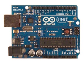
You can wire various sensors diretly to Arduino pins or use Arduino shields. Wiring one or two sensors directly to Arduino pins works OK, but with greater number of sensors this is not very convient as you have easily a hard to manage wiring mess.
Arduino Sensor shield
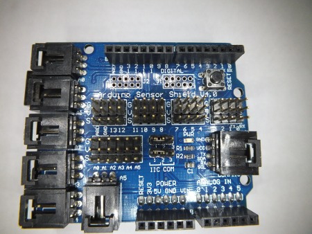
One way to easily connect many sensors to one Arduino board without hige wiring mess is to use Arduino Sensor Shield. Arduino Sensor Shield v4.0 is an easy way to connect input and output devices to Arduino. Arduino Sensor Shield provides three pin (ground, voltage, signal) interface for connecting all kinds of sensors (potentiometer, button, LDR etc.) and output devices (relay cards, servos etc..) to Arduino. The signal pins map directly to the different Arduino, so testing sensor shield can be done for example with StandardFirmata and toolduino.
Arduino sensor shield article has a good overview of the features:
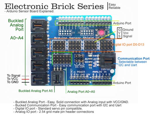
Sensor Shield is an easy way to connect INPUT DEVICES and OUTPUT DEVICES to Arduino. The Sensor Shield’s purpose is make it easy to connect cables and devices to the correct Arduino pins: It is a passive circuit board that simply connects the Arduino pins to many connectors. Those three pin connectors are ready to use to connect to various devices like Servos and Sensors with simple cables – allows you to connect to various modules like sensors, servos, relays, buttons, potentiometers just plug and play!
Each Port has 3 pins named with GVS letters:
G = Ground (cable code black)
V = Voltage +5V (cable color red)
S = Signal (cable color white or yellow)
By the way pinout is same as used in RC servos:
SIGNAL WIRE: Yellow, Orange or White (brand specific)
PLUS WIRE: RED
MINUS WIRE: Black or Brown
Those three pin ports are available as pin rows on the top of the circuit board. There are 13 ports prepared for Digital IO: digital input modules, digital output modules or servos. Depending on the programming different ports can be used as inputs and outputs. The digital ports have 5V power and TTL level digital signal pin (that can be depending on Arduino programming be used as input or output). A typical digital sensor outputs TTL level signal (logic 0 or 1) that connects to Arduino pin that is configured as input. Typical output devices either take digital 0/1 output signal from Arduino (for example relays, SSRs, on/off LEDs,. etc) or PWM signal (LED dimming, RC servo motors etc..). There are also applications where some sensors with built-in “smart” is connected to sensor port, and with suitable software the port can be used as one wire serial bus for input (1-wire DS1820 temprature sensor, DHT11, DHT22, etc.) or output device (LED with WS2812)
In addition to digital ports there are analog ports. There are 6 analog inputs that accept normally 0..5V DC input voltage (voltage range can be adjusted with Arduino programming and/or reference voltage setting). Typically Arduino sensors are designed such that they give out voltage in that 0..5V range. The pinout is same as in digital ports. In addition to pin rows on the circuit board those same analog inputs are also available as Buckled Analog Ports on the side of the circuit board to connect sensors with matching connectors.
In addition to those ports the sensor shield has Buckled Communication Port that is selectable between I2C and UART. It can be used to connect devices that use serial port communications or I2C bus to Arduino board.
This shield doesn’t do anything magical, and you won’t find any smoke and mirrors. It does provide easy, plug-in connectivity to the data pins on your Arduino. The connectors are grouped in a logical manner and are well-labeled
These shields are great and make it so much easier to work with Arduino when you need to connect input and output devices (and who doesn’t need to do that?). The digital and analog ports are broken out and it makes it so much easier to connect devices and cables using flat simple cables or buckled connectors.
So what kind of circuits those Arduino sensors are? Typicaly they are are usully quite simple circuits. Here is an example analog sensor circuit from Adafruit article Using a Photocell:

The more lights hits LDR, the smaller it’s resistance gets and higher voltage goes to the alogue input. When there is no light the voltage is almost 0V and when LDR is in bright light the output is alsmot 5V. Similar LDR sensors are available cheaply.
When building digital sensors check out this example circuit from Pushbuttons and tilt sensors/switches: how they work and some Arduino usage examples article. On the left side ircuit you see a simple switch circuit that gives out logic 0 (0V) when switch is open and logic 1 (5V) then button is pressed. On he circuit the button and 10 kohm resistor are pretty normal for this kind of circuit, but please take a none on the 220 ohms resistor: is a protection component that avoid damaging Arduino in case the button is pressed and Arduino I/O pin is accidentally configured to be output (the resistor limits the current that flows to pin to safe value that does not damage anything).

The Arduino sensor shield system is originally designed for systems that use 5V. There are also 3.3V systems that use the same pin-out for sensor connection and supply 3.3V instead of 5V (for example ARM based Arduino or ESP8266 NodeMcu breakout board). If you plan to use 3.3V system, you need to check case-by-case per sensor if the specific sensor you plan to use really works well also with 3.3V – some sensors only work with 5V and some work well with both 3.3V and 5V.
Here is one introduction video to using Arduino sensor shield:
GROVE System
There is another popular Arduno sensor system besides Sensor Shield. It is called Grove System. Grove compatible modules feature special 4 pin locking connectors with standardized pinouts for use with a variety of microcontroller GPIO pins. Grove system allows easily connecting Grove modules to your Arduino compatible microcontroller. – or Raspberry Pi.
Grove is a modular, ready-to-use tool set. Much like Lego, it takes a building block approach to assembling electronics. The Grove system consists of a base shield and various modules with standardized connectors. The Grove uses 4 pin connector that contains ground, power (5V or 3.3V) and two signal pins. There are different types of ports: Digital ports, Analog input ports and I2C ports.
Seeed Studio’s Grove is an ingenious way to create hardware interoperability between accessories made for maker. It uses a standard socket & pinout, supports more than 100 accessories already (from sensors to output, from displays to wireless communication). Usually these are accessed via a special shield (Grove base shield): those breakout boards make several microcontroller & computer platforms to be able to use these accessories (full scale Arduinos, Raspberry Pi, Intel Edison and Galileo, VIA VAB-820, and so on).
The Base shield allows for easy connection of any microprocessor input or output from the Grove modules, and every Grove module addresses a single function, such as a simple button or a more complex heart rate sensor. Check out Introduction to Grove for some more details.
Here are some details of Grove – Base Shield V1.3 for Arduino:
- SeeeduinoV2.21(168p and 328p),Arduino UNO and Duemilanove compatible
- Compatible with all Grove modules
- 7 Digital connectors (D2-D8)
- 4 Analog connectors (A0-A3)
- 4 I2C sockets
- NO SPI socket
- UART/D0-D1 connector
- ISP/ICSP header
- Green Power indicator LED
- Right angle reset button with red LED reset indicator
- Stacking connectors
- Simplified screen printing

Grove sensors use a special socket, a 4 pin JST with two power lines and two data. You can see that each of the connectors has two digital pins connected to it and then V (5V) and G (GND). The data pins are the pins you connect to the pins that are used in your sketch. Depending on the sensor type the sensor can use one of the data pins or both data pins.
To my understanding Grove system started as 5V system but nowdays mostly supports both 5V and 3.3V voltages. Every Grove connector has four wires, one of which is Vcc. However, not every micro-controller main board needs a supply voltage of 5V, some need 3.3V. Depending on the microcontroller platform you use, the voltage your Grove shield supplies to the sensors is 5V (for exmaple with Arduino Uno) or 3.3V (for example ARM based Arduinos and Raspberry Pi).
Introduction video to Grove system starter kit:
Sensor Shield vs. GROVE System
Both Sensor shield and Grove systems seem to be nice tools to connect sensors to Arduino and other microcontroller boards.
Sensor shield cheaper is cheaper and very many cheap sensors from many suppliers – but more messy wiring (can plug wires easily on on wrong way, some differences on different sensors 3 pin pinouts so direct 3 pin cable not always right.. etc.)
Grove seems to be to me more “ready product” but more expensive. The connectors have well defined pinouts and you can’t plug then wrong way. Grove shields are nowdays available for many other mcrocntroller platforms than just Arduino (for example Raspberry Pi).
Those Grove and Sensor shield systems are in many ways similar, so it is possible to adapt many sensors from one to another with converter cables (for example connect Sensor shield sensor to Grove).
I think both of those systems have their their places on the market.
50 Comments
Tomi Engdahl says:
Arduino Tutorial: Temperature Sensor
https://www.raywenderlich.com/38841/arduino-tutorial-temperature-sensor
The problem is, standard weather apps tell you about the temperature in a nearby city or suburb – but not necessarily about extremely local conditions. And what about that aquarium you would like to monitor, or your mini indoor greenhouse?
This is a job for the latest open source microcontroller – the Arduino.
In this tutorial, you’ll build an Arduino project for the iPhone that lets you connect multiple temperature probes you can place in different locations and query for their readings.
This tutorial requires some specific hardware components to interface with the temperature probes. You’ll be making use of a microcontroller (the Arduino), an Ethernet interface, and connecting status and temperature probes.
You might have initially thought about plugging the Grove Shield in first, then placing the Ethernet Shield on top of that. Unfortunately, this won’t work due to the Grove Shield not passing the 6 pins on the back through to the front.
To install the Grove Shield, first turn off your Arduino by disconnecting it from the USB connector.
Carefully place the Grove Shield board in place onto the stackable headers without bending or missing any pins.
Reading Temperatures
Open the LEDBlinkAndEthernetFakeTemperatureJSON sketch
Earlier in the JSON section, you had two variables, temperatureIndoor and temperatureOutdoor, that for testing purposes had hard-coded temperature values. Now comes the magic of the sensors: you’ll use these same variables, but store real temperatures in them.
Now comes the iOS! You will build an iPhone app to get your temperatures.
Tomi Engdahl says:
Seeed’s Grove
dscf8958Meanwhile in China, Seeed Studios makes open-source modules, and makes them cheap. Their Grove connector uses only four pins, with power and ground among them. The have standard pinouts for UART, I2C, and for servo motors. Sensors and other analog peripherals are allocated one “primary” pin and one “secondary” and it’s assumed that you know what you’re doing. The idea behind their system is that you add a shield to your microcontroller board, and they break out the relevant pins into these four-pin Grove headers.
This is great for small things and I2C devices, which is Seeed’s catalog, but there just aren’t enough signal pins to run SPI or an analog RGB LED, for instance. But because of the small number of pins, they use very inexpensive polarized cables and shrouds that you can’t plug in the wrong way, and that take up relatively little board space. That’s Grove’s design trade-off.
Source: http://hackaday.com/2016/11/09/my-life-in-the-connector-zoo/
Tomi Engdahl says:
Grove System
http://wiki.seeed.cc/Grove_System/
Grove is a modular, standardized connector prototyping system. Grove takes a building block approach to assembling electronics. Compared to the jumper or solder based system, it is easier to connect, experiment and build and simplifies the learning system, but not to the point where it becomes dumbed down. Some of the other prototype systems out there takes the level down to building blocks. Good stuff to be learned that way, but the Grove system allows you to build real systems. It requires some learning and expertise to hook things up.
The Grove system consists of a base unit (stem) and various modules (twigs) with standardized connectors.
The Base unit, generally a microprocessor, allows for easy connection of any input or output from the Grove modules. And every Grove module typically addresses a single function, such as a simple button or a more complex heart rate sensor.
You don’t need a Base unit to connect up to Grove modules. You can use a cable (Grove to Pin Header Converter) to run from the pins on the Raspberry Pi or Arduino to the Grove connectors.
Grove Projects
Tomi Engdahl says:
Hobby servo motors need three wires: voltage, ground, and a signal to tell them where to point. There are three distinct ways to arrange these wires, but Futaba, HiTec, Tower, GWS, and JR servos all chose to put them in SVG (or GVS) order, and there’s no reason to buck the trend. (Airtronics, what were you thinking?!)
SVG is also a handy pinout to use for all sorts of one-signal sensors or actuators where space is a premium
Source: http://hackaday.com/2016/11/09/my-life-in-the-connector-zoo/
Epson Support says:
Hii, Thanks for the sharing nice posting with us. i’m really impressed.
Contact Mcafee Antivirus Support says:
very awesome article, thanks for the sharing with us.
Sumantha Black says:
Hey! Nice post thanks for sharing this…..if you want any solution related to windows than visit here:
Acer Customer Service says:
Hello there, just became aware of your site via
Google, and discovered that it’s truly useful. I’ll be happy if you
continue this in future.
Tomi Engdahl says:
The 4-20 mA Current Loop
http://hackaday.com/2017/07/19/the-4-20-ma-current-loop/
The I/O capabilities built into most microcontrollers make it easy to measure the analog world.
Now put a twist on it: you need to mount the sensor far from the microcontroller. The longer your wires, the bigger the voltage drop will be, until eventually your five-volt swing representing a 100° range is more like a one-volt swing. Plus your long sensor leads will act like a nice antenna to pick up all kinds of noise that’ll make digging a usable voltage signal off the line all the harder.
Luckily, industrial process engineers figured out how to deal with these problems a long time ago by using current loops for sensing and control. The most common standard is the 4-mA-to-20-mA current loop
The now standard 4-20 mA current loop for process control descends directly from an early innovation in industrial automation, pneumatic process control.
While pneumatic systems are very much still in use today, especially in industries where things tend to go boom around electricity, 4-20 mA current loop systems became a de facto standard in the 1940s and 1950s.
Current loops aren’t limited to sensors, of course. A wide range of actuators, from valves to motor drives, can be controlled by a 4-20 mA loop. Data acquisition and display are also possible, with chart recorders, gauges, and indicators all available for the loop.
So how do you incorporate a 4-20 mA device into your latest Arduino project? Changing the current back to a voltage by putting a resistor in the loop and measuring the voltage drop across it is really all it takes. [AvE] does the math to show us that a 250-ohm resistor gives us a one-volt to five-volt swing, which is perfect for an Arduino’s analog input
4-20mA Industrial Sensor + Arduino
https://www.youtube.com/watch?v=6di24oIdISs
How to build a simple 4-20mA transducer circuit on Arduino. It’s easy: add a 250 ohm resistor. If you want more protection for the Arduino, you’ll need to add zener diodes and a 10k resistor to the Arduino analog pin
Tomi Engdahl says:
PobDuino Makes the Most of Grove
http://hackaday.com/2017/07/27/pobduino-makes-the-most-of-grove/
The chassis of a toy robot serves as the base of a robot built by [Jean Noel]. Called #PobDuino, the robot features two Arduino-compatible boards under the hood.
First, a Seeeduino Lotus, a Arduino board peppered with a dozen Grove-compatible sockets. The board, which is the size of an UNO, is mounted so that the plugs project out of the front of the robot, allowing ad-hoc experimentation with the various Grove System modules.
Robot #PobDuino
https://hackaday.io/project/26009-robot-pobduino
A bicephale robot, taking the best from Arduino & grove ecosystem, augmented with Flowcode graphical progamming
Tomi Engdahl says:
Arduino Sensor Kit 37 In 1
http://www.epanorama.net/newepa/2017/07/21/arduino-sensor-kit-37-in-1/
Arduno neeeds sensors. Geekcreit® 37 In 1 Sensor Module Board Set Kit For Arduino Plastic Bag Package promises to give many sensors cheaply.
HP Contact Number says:
This is my first time to visit here. I found countless interesting
stuff in your weblog, especially in its discussion. I guess I’m not the only one having
all the entertainment here!
Tomi Engdahl says:
Related posting:
Arduino Sensor Kit 37 In 1
http://www.epanorama.net/newepa/2017/07/21/arduino-sensor-kit-37-in-1/
Tomi Engdahl says:
TinkerKit!
https://www.youtube.com/watch?v=LlhLyJoVO9c
Think you will never be able to build anything with electronics? TinkerKit! will prove you very wrong, really fast.
TinkerKit Tutorial: Basics: 01 – Introduction
http://www.carobot.cc/how-to/tinkerkit-tutorials/tinkerkit-tutorial-basics-01-introduction/
TinkerKit is a tool used to build interactive products in a simplified way and in a short amount of time. It works with the Arduino board
Thanks to the modular system of the blocks, all you need to do is plug them using snapping cables.
The modules are divided in sensors and actuators.
TInkerKit Shield, where all the components are plugged. Just like the modules, it is split in two parts: one for INPUTS and one for OUTPUTS. Each part has six ports, numbered from 0 to 5. INPUT ports are called I0, I1, I2, I3, I4 and I5 while OUTPUT ports are O0, O1, O2, O3, O4 and O5.
The TinkerKit Shield it’s an Arduino extension.
Tomi Engdahl says:
TinkerKit
-
LAB
https://www.distrelec.nl/Web/Downloads/_t/ds/K000005_eng_tds.pdf
Tomi Engdahl says:
Arduino Esplora Tinkerkit Outputs
http://21stdigitalhome.blogspot.fi/2013/01/arduino-esplora-tinkerkit-outputs.html
The new Arduino Esplora has two orange output connectors at the top left of the device.
To connect, you’ll want 3-pin molex connectors. They are commonly used for PC fans.
Tomi Engdahl says:
Tinkerkit pinout:
+5V
Digital pin
Ground
Tomi Engdahl says:
TinkerKit
https://github.com/TinkerKit
Tomi Engdahl says:
LinkerKit
http://www.linksprite.com/
http://linksprite.com/wiki/index.php5?title=LinkerKit_for_Raspberry_Pi
Tomi Engdahl says:
LinkerKit sensor are quite similar to GROVE system:
uses 4 pin JST XHS-4 connector that contains ground, power and two signal pins.
Sensor power is typically 5V
Some pinouts (typically printed on modules)
SCL
SDA
DCC
GND
SIG
nc
VCC
GND
Tomi Engdahl says:
Turn a lamp on and off with a Raspberry Pi and a Linker Kit Relay
https://christoph-rumpel.com/2016/02/Turn-lamp-on-off-with-rasperrypi-and-linker-kit-relais/
The Pi is able to control a 5V relay and in combination we can turn the lamp on or off.
Tomi Engdahl says:
LinkerKit for Raspberry Pi
http://linksprite.com/wiki/index.php5?title=LinkerKit_for_Raspberry_Pi
Tomi Engdahl says:
TinkerKit Tutorial: Basics: 01 – Introduction
http://www.carobot.cc/how-to/tinkerkit-tutorials/tinkerkit-tutorial-basics-01-introduction/
The modules are divided in sensors and actuators.
http://forum.arduino.cc/index.php?topic=180278.0
Can anyone tell me what the pin outs are for the Tinkerkit 3-pin (used for digital/analog) connector and 4-pin (1-wire) connector please? These both use the Molex KK 0.1″ pitch style connectors.
The three-pin connectors have Power (red), Arduino Pin (orange), and Ground (black) counting from top to bottom.
One 4-pin socket is TWI (I2C) and the other is Serial. The pins seem to be ? (orange), ? (blue), Power (red), and Ground (black) top to bottom.
Tomi Engdahl says:
From:
http://forum.arduino.cc/index.php?topic=180278.0
Tinkerkit – the ubiquitous Molex KK. Why the KK isn’t used on more boards I don’t know – they’re cheap and reliable and keyed so you can’t mess up. The crux of the issue is I don’t want to start a new standard for my board if one already exists. There are already too many standards in the world – driving on the left/right of the road, 220V/230V/240V/110V/115V electricity, 50/60Hz, the list goes on. It would be a lot easier if all these pointless differences had never been started in the first place. Having said that, Tinkerkit gear doesn’t seem to be all that popular, so using it as a defacto standard just because it’s the only standard around might not be wise either. I have been thinking in fact about using the GND, VCC, SIGNAL ordering on my 3-way connectors. People can install just 0.1″ pitch bare headers on the board if they want and plug in steppers, sensors, or anything that’s GND, VCC, SIGNAL ordering.
At least the Tinkerkit shield uses polarized connectors.
Tomi Engdahl says:
tinkerkit sensor pinout
https://books.google.fi/books?id=7oMpDAAAQBAJ&pg=PA286&lpg=PA286&dq=tinkerkit+sensor+pinout&source=bl&ots=fc27ueQNBw&sig=WeWH9SAwY4-ILtx68E9GiJMQNlE&hl=fi&sa=X&ved=0ahUKEwiZgJiTtN_bAhUBiywKHYZHAy8Q6AEIcTAM#v=onepage&q=tinkerkit%20sensor%20pinout&f=false
Tomi Engdahl says:
The Pimoroni “Breakout Garden” for the Raspberry Pi
https://blog.hackster.io/the-pimoroni-breakout-garden-for-the-raspberry-pi-6e6468033d68
another standard is born. In fact, I see enough connector systems that I’m automatically skeptical of new ones, and generally dismiss them until they’ve hung around for a few years and proved themselves useful.
Enter the new “Breakout Garden” from Pimoroni
The Pimoroni breakout standard is sort of reminiscent of the Seeed Studio Grove System, but has been built with the Raspberry Pi firmly in mind.
“…designed it so that you can solder a piece of right-angle header onto it and then pop it straight onto the bottom left 5 pins on your Raspberry Pi’s GPIO header (pins 1, 3, 5, 7, 9).”
https://shop.pimoroni.com/products/breakout-garden-hat
Mona Roy says:
I must say a nice article has been written by the author.
Covering this topic in a single article was very difficult but I see that how nicely the author has done it.
Author has given very amazing facts and information on this interesting topic.
Canada Immigration Consultants
Canada PR Visa Process
Immigration PR Visa
Tomi Engdahl says:
https://www.seeedstudio.com/grove.html
Easy Immigration says:
Took me time to read all the comments, but I really enjoyed the article. It proved to be Very helpful to me and I am sure to all the commenters here! It’s always nice when you can not only be informed, but also entertained!
Immigration services for PR Visa
Top Immigration Consultants
Easy Immigration
Tomi Engdahl says:
Connecting Multiple Sensors to One Arduino Uno Serial Port © CC BY-NC
https://create.arduino.cc/projecthub/atlas-scientific/connecting-multiple-sensors-to-one-arduino-uno-serial-port-181d48
How to connect multiple Atlas sensors to a single Arduino serial port.
Tomi Engdahl says:
Add Increased Functionality to Your Arduino and Raspberry Pi with TinyCircuits’ Whiskers
https://blog.hackster.io/add-increased-functionality-to-your-arduino-and-raspberry-pi-with-tinycircuits-whiskers-43ae602f19c7
Open source electronics maker TinyCircuits has launched a crowdfunding campaign to bring their tiny Whisker add-on boards to the market. The boards act in a similar fashion to Raspberry Pi HATs and Arduino shields, adding everything from sensors to 9-axis IMUs.
The Whiskers connect to the Pi/Arduino/TinyDuino via a 5-pin cable, which means there is no soldering required
to use the Whiskers with those boards, they need a HAT/shield adapter, which is outfitted with the necessary jacks to add up to four additional boards
TinyCircuits state they have developed over 30 Whisker boards — including a myriad of sensors
Tomi Engdahl says:
A Capacitive Soil Sensor Hack For Lower Voltage Supplies
https://hackaday.com/2019/07/27/a-capacitive-soil-sensor-hack-for-lower-voltage-supplies/
Tomi Engdahl says:
Grove Sensor Tester – Get Sensor Value in Seconds – Arduino
A simple low cost tool to get analog/digital value of your Grove sensor in seconds, no PC and coding required, quick and straight.
https://www.hackster.io/Makerming/grove-sensor-tester-get-sensor-value-in-seconds-arduino-46f933
Tomi Engdahl says:
SparkFun’s New Qwiic Boost Makes Running 5V Devices on Your 3.3V I2C Bus a Cinch
Compact board allows devices to run at 5V while still providing 3.3V logic — though 5V logic is also selectable with an on-board jumper.
https://www.hackster.io/news/sparkfun-s-new-qwiic-boost-makes-running-5v-devices-on-your-3-3v-i2c-bus-a-cinch-006c73037a90
Tomi Engdahl says:
[10,14€]Seeeduino Nano Atmega328P 8-bit AVR Microcontroller with Grove Connector I2C Development Board Motherboard & Development Board from Electronic Components & Supplies on banggood
https://banggood.app.link/0DOILINGFbb
Tomi Engdahl says:
Grove – DMX512
https://www.digikey.fi/product-detail/en/seeed-technology-co.,-ltd/103020000/1597-1385-ND/5487875?utm_adgroup=Evaluation%20Boards%20-%20Expansion%20Boards%2C%20Daughter%20Cards&utm_source=google&utm_medium=cpc&utm_campaign=Shopping_Product_Development%20Boards%2C%20Kits%2C%20Programmers&utm_term=&productid=5487875&gclid=EAIaIQobChMIounx9Zrg8gIVDMgYCh3JGAvxEAQYASABEgJvWPD_BwE
Tomi Engdahl says:
DMX SHIELD FOR ARDUINO
https://www.digikey.fi/product-detail/en/dfrobot/DFR0260/1738-1246-ND/7087143?gclid=EAIaIQobChMIounx9Zrg8gIVDMgYCh3JGAvxEAQYAyABEgLGT_D_BwE
Tomi Engdahl says:
Secrets of Arduino PWM
https://www.arduino.cc/en/Tutorial/SecretsOfArduinoPWM
Arduino PWM and Analog Output
https://www.halvorsen.blog/documents/technology/resources/resources/Arduino/Arduino%20PWM.pdf
Tomi Engdahl says:
Arduino PWM output and its uses – The definitive guide
https://technobyte.org/arduino-pwm-output-uses-generation-control/
In this tutorial, we are going to learn how to perform Arduino PWM (Pulse Width Modulation). We will take a look at how PWM is generated in an Arduino and also try out a couple of applications like dimming an LED and running some motors. Let’s begin!
Tomi Engdahl says:
Handheld Readout Device(HRD) for Sensors
Readout Device for all I2C Sensors
https://hackaday.io/project/181706-handheld-readout-devicehrd-for-sensors
Tomi Engdahl says:
https://hackaday.com/2022/04/03/hackaday-links-april-3-2022/
Speaking of components, here’s another treat for you: Tim Hunkin is releasing a second season of his “Secret Life of Components” series. The first season wrapped up almost a year ago, but Tim says it proved so popular and garnered enough donations that he was able to do it again. The first of five videos, “The Secret Life of Sensors,” was released this past Thursday.
SENSORS -The Secret Life of Components, a series of guides for makers and designers – episode 9
https://www.youtube.com/watch?v=FNnP84tTSFY
Tomi Engdahl says:
Grove Photo Resistor (LDR)
Grove Photo resistor board with I2C interface
https://hackaday.io/project/187189-grove-photo-resistor-ldr
This sensor board with a photo resistor (LDR) has an I2C interface for Seeedstudio Grove.
An LDR is an ideal sensor for light detection or sensing the light.
Most LDR applications provide an analog voltage output. This Grove photo resistor board has an additional I2C interface with a 4-pin Grove connector..
The onboard Analog-Digital-Converter (ADC) converts the analog sensor value in a digital signal.
The I2C interface enables the user to use the sensor board with different microcontrollers (i.e. Arduino, Raspberry Pi, ESP8266 and more).
Tomi Engdahl says:
https://www.partco.fi/fi/2422-grove-breakouts
Tomi Engdahl says:
Ready to participate in the Grove Sensor Co-brand Campaign but don’t know how to prepare? How should creators go about designing Grove modules? What are Grove modules? What should designers pay attention to?
Today’s blog is intended to provide guidance for PCB designers and more:
1. What is Grove?
2. Types of Grove Modules
3. What qualifies as a Grove Module?
4. Which Grove Connector Should I use?
5. How to include the Grove connector in the Bill of Materials (BOM) file?
6. PCB Layout Tips
7. Tips to Reduce Costs
Read the full blog to learn more: https://lnkd.in/g3kRhMVA
Are you ready to explore with us and co-create endless Grove sensors to solve real-world challenges? Seeed Fusion launched the Grove Sensors co-branding campaign to help engineers turn their Grove designs into products the community can purchase.
If you also can’t wait to spark your idea with Grove, welcome show your design now: https://lnkd.in/gDwW5N5v
#design #work #community #branding #engineers #designers #help #guide #contest #Grove
Tomi Engdahl says:
https://www.seeedstudio.com/blog/2022/11/18/seeed-grove-designers-guide-pcb-design-guidelines-and-more/?utm_source=mailchimp&utm_medium=edm&utm_campaign=20221117&mc_cid=dc54b823ce&mc_eid=9c82854d46
Tomi Engdahl says:
Why most Arduino Soil Moisture Sensors suck (incl. solution)
https://www.youtube.com/watch?v=m0mcCtcViTY
Unfortunately, most soil moisture sensors used in our Arduino, ESP8266, or ESP32 projects destroy themselves after a short while. We need a better solution.
Today we will test different sensors, and I will show you how they work and why most sensors from China destroy themselves. And, of course, we will find a solution to the problem.
#207 Why most Arduino Soil Moisture Sensors suck (incl. solution)
https://www.youtube.com/watch?v=udmJyncDvw0
Tomi Engdahl says:
Sensors – which one to use
https://www.youtube.com/watch?v=DlG6LY84MUU
Tomi Engdahl says:
Display examples – which one to use?
https://www.youtube.com/watch?v=H4OuxIwLgHw
Tomi Engdahl says:
https://www.sparkfun.com/qwiic
Makeup Artist in Jalandhar says:
Thank you so much for this amazing post.