I happened to find this AnyTronics 4 channel dimmer thrown out as trash. It looks looks like Anytronics wall mounted dimmer 4 x 10 A that someone has adapted to become rack mounted and moved the DMX-512 address selection switches outside the device. I expected that Anytronics DP410 dimmer pack installation instructions would be about right for this, but after some testing revelealed that that was not the case.

Next task was to look what is inside. This looks as pretty typical 4 channel analogue controller light dimmer, and resembles pretty much the design of newer models. As you can see there are some wires that go to the fuses cut out and most fuse holders missing, So there is something to be fixed before this can be used.
The basic circuitry looks pretty normal. The main board has triacs with heatsinks, control electronics, filtering component (big coils because they need to handle 10A current) and related. The board has pretty good markings what is what in there. It seems that the board is designed so that it can be used to build several different dimmer models (4 and 8 channel dimmers). On the right you can see an extra circuit board that does DMX-512 to anlogue (0-10V) conversion.

The dimmer circuit outlook looks pretty normal. This is four channel dimmer powered from one phase 230V AC 50 Hz mains power. Because the dimmer can output 10A per channel, it will need to be powered from 40A 230V power source if you want to use all the capacity. If you don’t need to use all the power, lower amperage power feed is OK (for example 230V 16A).
The dimmer circuit looks at quick outlook as pretty normal looking analogue dimmer design. There is a low voltage side (powered with one transformer) where there is a ramp voltage generator, and a set of voltage comparators (LM324) that feed opto-isolators. The basic construction of control circuit design look somewhat similat to SchematicsForFree disco power pack and my four channel dimmer pack design. On the mains voltage side of opto-isolators there is circuitry needed to trigger the triacs (powered with the second transformer).
Here is a closer look of the DMX-512 to analogue 0-10V adapter circuit board. The board looks pretty much like homemade circuit board. The main components there 7805 regulator, RS-485 transceiver IC, microcontroller with DMX4ALL label one one IC made by Maxim. This board takes DMX-512 signal and converts it to analogue signal that goes to main dimmer board.

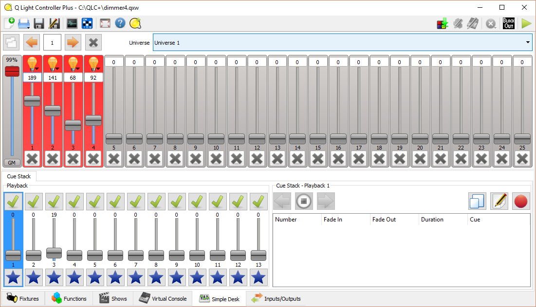
I wanted to test the DMX-512 part, so I needed to fix the problems on the dimmer power wiring, and get suitable hardware + software to generate DMX-512 signals from PC. For harware interfacing I used my pwn USB-to-DMX-512 adapter I had built years ago based on popular open hardware OpenDMX USB design (based on a FT232BM chip and RD-485 transceiver). I did some testing first with Q Light Controller software that provided easy to use basic light desk (worked on old Windows XP PC, not with Open DMX adaper on Windows 10 due some driver issues). On the newer PC I started to use Q Light Controller Plus software that worked well.
The end result was that I have now a working DMX-512 controlled light dimmer.
17 Comments
Tomi Engdahl says:
Arduino ETC Dimmer Module
https://www.youtube.com/watch?v=KYKhu9xGHTk
Tomi Engdahl says:
Dimmer Packs
https://www.youtube.com/watch?v=MYhKQ5rxOO4
Ben says:
Hello Tomi, Thanks for sharing your info on your dimmers, specially your 4 ch 100hz control dimmer as you did in 1998-2000. And here I meet you again, on the same subject: Dimmers.
I can work wih them, but nowadays i’m learning the electrical matters : how ithe components work, how the waves ar changed into a saw teeth and firing the Triac. As I yhave a couple of vintage dimmers from the 1980′s , and also a super Demuxer 72 channels, I’m trying to restore some old channels. The foto attached show you a 2 channel card which alike your diagrams. Its a 2 ch card from an pilot serie from IES 1989 I’ve six working cards, and I want to learn all about them, to keeap them alive, they are very handy for small projekts.
Plse have a look and let me know if I’m right that they a like your design.
Specially how the signals 010V in, the vcc 12v, the Sawteeth in and the firing sign to the triac are working in the LM324. Ok Ihope You have a couple of spare minutes to answer, anyway thanks ,
att foto of card, see link https://ahp.li/1981ea99ef6910561849.jpg
and when you’re intrested I can show you some other dimmers I’m working on.
Greetz
Ben
Tomi Engdahl says:
You must be referring to my dimmer design that can now be found at http://www.epanorama.net/circuits/dimmer4.html
I have personally built two such dimmer units and used them in various applications from DJ light setups to controlling some lights on one TV show.
“Plse have a look and let me know if I’m right that they a like your design.
Specially how the signals 010V in, the vcc 12v, the Sawteeth in and the firing sign to the triac are working in the LM324. Ok Ihope You have a couple of spare minutes to answer”
I took a quick look, and based on that it looks like the design would be pretty similar as on my old dimmer design. This is a result of quick look I took, I did not do complete reverse-engineering based on picture as it is more time consuming than few minutes.
Feel free to post links to pick of dimmers you are working on, so I get the idea with what you are working with.
Ben says:
Thanks Tomi for your quick reply,
and yes there’s no need for more than a quick impression.
First I ‘ll do a proper schematic on what I have, and I ‘ll use your schematics as guideline.
If I have a detailed question I’ll sent you a message, if you don’t mind..
I gonna make some pics on my stuff, and will send you a link.
Tomi Engdahl says:
DIN rail Dimmer Module, 4 Channels, 3.3V/5V logic, AC 8A/300V per channel
https://www.aliexpress.com/item/1005001713267386.html?spm=a2g0o.detail.1000060.3.1b197a64DyfzuS&gps-id=pcDetailBottomMoreThisSeller&scm=1007.13339.291025.0&scm_id=1007.13339.291025.0&scm-url=1007.13339.291025.0&pvid=82e69196-1889-4298-892d-8ce7a012e105&_t=gps-id:pcDetailBottomMoreThisSeller,scm-url:1007.13339.291025.0,pvid:82e69196-1889-4298-892d-8ce7a012e105,tpp_buckets:668%232846%238109%231935&isseo=y&pdp_npi=3%40dis%21EUR%2116.94%2116.6%21%21%21%21%21%402101c80016866780202764940eb245%2112000025595505319%21rec%21FI%21
DIN rail Dimmer Module for control of lamps, motors, heaters, 1 Channel, 3.3V/5V logic, AC 300V/8A
Product Overview
The AC Dimmer is designed to control the alternating current voltage, which can transfer current up to 300V (8A) (TRIAC BTA16 for 600V/16A but we don’t recommend up power to this level). In most cases, Dimmer is used to turning power ON/OFF for lamps or heating elements, it can also be used in fans, pumps, air cleaners, e.t.c.
Lately, Dimmer has become an often used decision for the smart home systems. For example, when you need to smoothly change the light brightness. The lamp is slowly turning ON or OFF, creating a comfortable atmosphere. Dimmer works most effective with filament lamps. It’s less stable with low brightness LED lamps, but with moderate and high brightness it will perform a solid job. Note that luminescent lamps (gas discharge lamps) do not support dimming.
Power part of dimmer is isolated from the control part, to exclude the possibility of high current disruption to a microcontroller.
The logical level is tolerant to 5V and 3.3V, therefore it can be connected to the microcontroller with 5V and 3.3V level logic.
In Arduino, the dimmer is controlled with RBDdimmer.h library, which uses external interrupts and process time interrupts. It simplifies the code writing and gives more processing time for main code. Which is why you can control multiple Dimmers from one microcontroller.
You can download RBDDimmer.h library and a few examples in «Documents» or on GitHub. We are constantly updating our library, so we recommend to check for the website updates or subscribe to our newsletter.
Dimmer is connected to Arduino controllers via two digital pins. First (Zero) to control the passing of Phase Null of AC, which is used to initiate the interrupt signal. Second (DIM/PSM) to control (dim) current.
Note that Zero requires connection to designated microcontroller pins (which are different depending on the model of Uno, Nano, Leonardo, Mega), since it tied to microcontroller interrupts.
Tomi Engdahl says:
DIN rail Dimmer Module, 2 Channels, 3.3V/5V logic, AC 8A/300V per channel
https://www.aliexpress.com/item/1005001712835760.html?spm=a2g0o.detail.1000060.3.55804ae5OnwWKv&gps-id=pcDetailBottomMoreThisSeller&scm=1007.13339.291025.0&scm_id=1007.13339.291025.0&scm-url=1007.13339.291025.0&pvid=46d41958-620d-4ee0-bc8f-1854a55e32c4&_t=gps-id:pcDetailBottomMoreThisSeller,scm-url:1007.13339.291025.0,pvid:46d41958-620d-4ee0-bc8f-1854a55e32c4,tpp_buckets:668%232846%238109%231935&isseo=y&pdp_npi=3%40dis%21EUR%2112.1%2111.87%21%21%21%21%21%402101c80016866780352045299eb245%2112000025595590349%21rec%21FI%21
AC Light lamp dimming and motor Dimmer Module, 1 Channel, 3.3V/5V logic, AC 50/60hz, 220V/110V – 600V
https://www.aliexpress.com/item/32802025086.html?spm=a2g0o.detail.1000060.1.73a75456OoSiFN&gps-id=pcDetailBottomMoreThisSeller&scm=1007.13339.291025.0&scm_id=1007.13339.291025.0&scm-url=1007.13339.291025.0&pvid=4baf639f-d8c9-4227-a412-8c232f486707&_t=gps-id:pcDetailBottomMoreThisSeller,scm-url:1007.13339.291025.0,pvid:4baf639f-d8c9-4227-a412-8c232f486707,tpp_buckets:668%232846%238109%231935&isseo=y&pdp_npi=3%40dis%21EUR%213.6%213.53%21%21%21%21%21%402103250716866791509996890eb19d%2112000021790017823%21rec%21FI%21
Tomi Engdahl says:
Dimmer module for 16/24A 600V High Load, 1 Channel, 3.3V/5V logic
https://www.aliexpress.com/item/1005001965951718.html?spm=a2g0o.detail.1000060.2.5706657c6zFGY3&gps-id=pcDetailBottomMoreThisSeller&scm=1007.13339.291025.0&scm_id=1007.13339.291025.0&scm-url=1007.13339.291025.0&pvid=0a5dc018-79e3-4191-886d-afed6eda0aad&_t=gps-id:pcDetailBottomMoreThisSeller,scm-url:1007.13339.291025.0,pvid:0a5dc018-79e3-4191-886d-afed6eda0aad,tpp_buckets:668%232846%238109%231935&isseo=y&pdp_npi=3%40dis%21EUR%219.68%219.49%21%21%21%21%21%402103250716866791749087430eb19d%2112000018256785548%21rec%21FI%21
Tomi Engdahl says:
AC Light lamp dimming and motor Dimmer Module, 1 Channel, 3.3V/5V logic, AC 50/60hz, 220V/110V – 600V
https://www.aliexpress.com/item/32802025086.html?spm=a2g0o.productlist.main.3.3137ahVlahVlbu&algo_pvid=a7baad81-e9d4-4b51-aa20-a50bb5758b02&algo_exp_id=a7baad81-e9d4-4b51-aa20-a50bb5758b02-1&pdp_npi=4%40dis%21EUR%214.75%214.61%21%21%215.07%214.92%21%402101fb0f17054154895335028ed154%2112000019986399741%21sea%21FI%21714587287%21&curPageLogUid=Ll7XfLueO8B9&utparam-url=scene%3Asearch%7Cquery_from%3A
Tomi Engdahl says:
AC Light Dimmer Module, 4 Channel, 3.3V/5V logic, AC 50/60hz, 110V~400V, 10A per channel
https://www.aliexpress.com/item/32975095882.html?spm=a2g0n.detail.1000013.7.5d096vjY6vjY8p&gps-id=storeRecommendH5&scm=1007.18500.300835.0&scm_id=1007.18500.300835.0&scm-url=1007.18500.300835.0&pvid=8f32737b-a0b4-4012-a4a4-6bf031152eb3&_t=gps-id:storeRecommendH5,scm-url:1007.18500.300835.0,pvid:8f32737b-a0b4-4012-a4a4-6bf031152eb3,tpp_buckets:668%232846%238107%231934&pdp_npi=4%40dis%21EUR%2110.86%2110.64%21%21%2111.42%2111.19%21%402101ef8717073322083666565ef6d1%2112000028217289430%21rec%21FI%212528467667%21
Tomi Engdahl says:
https://github.com/RobotDynOfficial/RBDDimmer
Tomi Engdahl says:
Another good article from ETC which calculates that neutral overcurrent can actually be as high as 1.7 times the the hot circuit current. https://support.etcconnect.com/ETC/Power_Controls/General/Common_Neutral_Wiring_in_ETC_Systems
Tomi Engdahl says:
Typically problems in signal wires don’t burn the DMX-512 equipment. Signal wires short circuit, signal wires cut, mixed wiring and wrong cable impedance just lead to not working. Overvoltage can kill the line transceiver chips if not very well protected (protection level varies between equipment). Lack of grounding in devices, cut ground shield on data cable, ground loops and ESD can cause overvoltages that can potentially damage the components typically near the input and output ports.
Tomi Engdahl says:
https://robotdyn.com/ac-light-dimmer-module-1-channel-3-3v-5v-logic-ac-50-60hz-220v-110v.html
https://www.aliexpress.com/item/32802025086.html
Tomi Engdahl says:
https://www.thomann.de/blog/en/dmx-basics-lighting-control/
Tomi Engdahl says:
LD-360
https://static1.squarespace.com/static/6470e7ae04b44c3cc8d082db/t/698ca91be955994c805c06f3/1770826011453/21-1044D+Manual.pdf
Tomi Engdahl says:
https://www.littlite.com/lepmanuals