I need power supplies for different eletronics circuits. I decided to get some cheap switch mode power supply modules 5Pcs Mini DC Adjustable Power Supply Buck Module Step Down Module (available also as single unit). The ideas was to try to use them instead of power wasting traditional linear regulators.
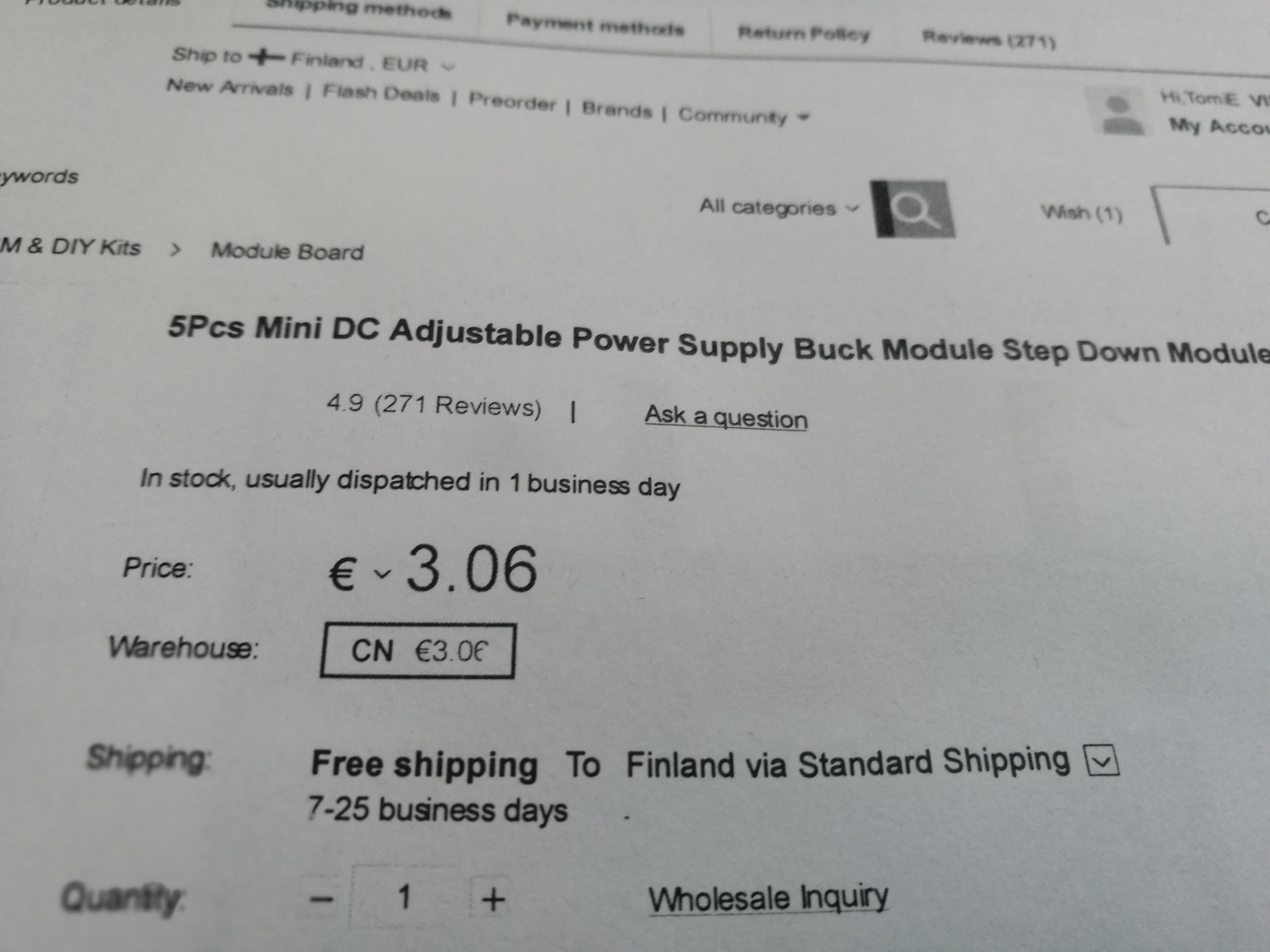
5Pcs Mini DC Adjustable Power Supply Buck Module Step Down Module
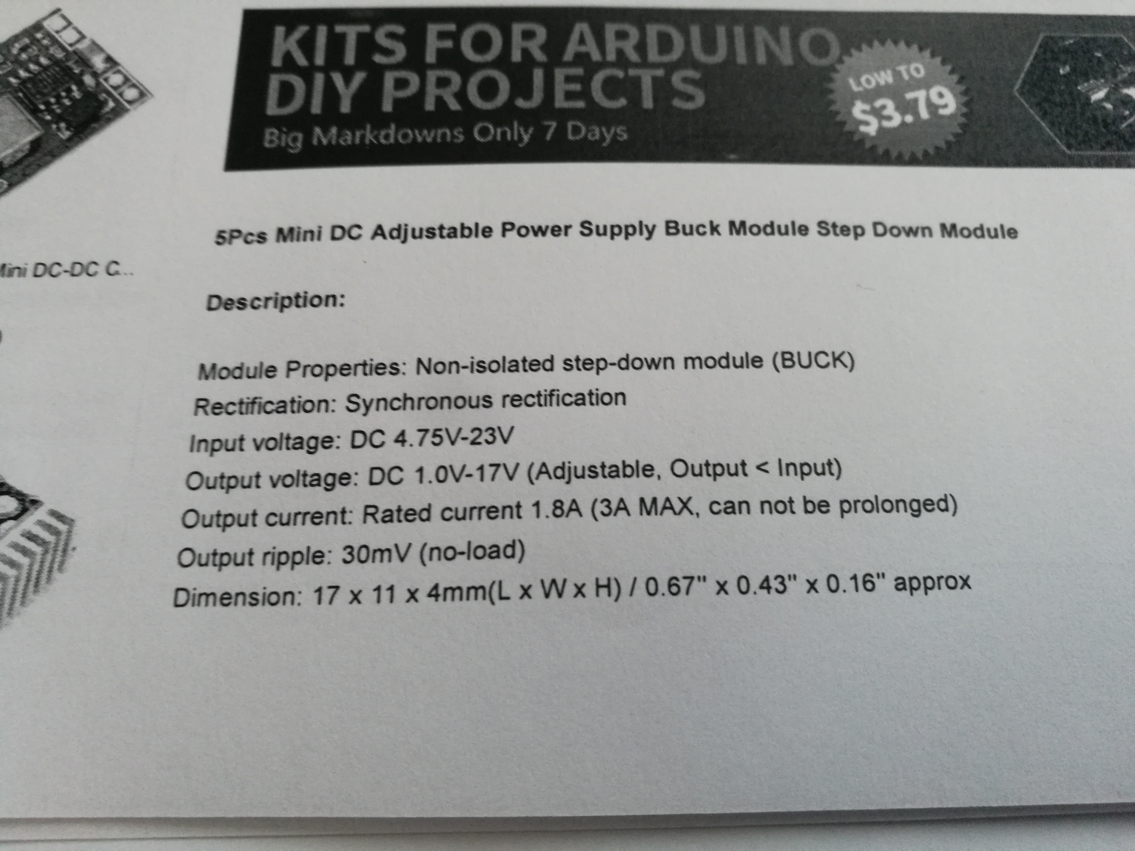
Description:
Module Properties: Non-isolated step-down module (BUCK)
Rectification: Synchronous rectification
Input voltage: DC 4.75V-23V
Output voltage: DC 1.0V-17V (Adjustable, Output < Input)
Output current: Rated current 1.8A (3A MAX, can not be prolonged)
Output ripple: 30mV (no-load)
Dimension: 17 x 11 x 4mm(L x W x H) / 0.67” x 0.43” x 0.16” approx
Weight: 1g (per.)
Price: USD 3.50 / EUR 3.07
Comments on product page seem promising:
- Very useful cheap and tiny DC step down modules!
- I like this little modules, they provide adjustable poweroutput and are so light !
-This is really small… 1cm x 2cm… easy to place in the quad with no issues.
- works really good pretty cheap and does the job perfectly
- I’ve been using these little voltage regulators for a while and never had a problem with a single one, they’re very useful. Just remember to use a plastic or ceramic screwdriver to adjust the trim pot or else it will interfere with the reading or even cause an unintentional short.
-Easy to attach and adjust, small and cheap enough to fix (semi)permanently using hot glue and shrink wrap to make power cables for random voltage devices. Convenient to have these in the toolbox so you’ll always have the voltage for any device from 12V supply or pretty much anything you might have available.
Even those Comments on product page did not seem to be too bad:
- The trimmer pot is s bit too close to the inductor (shown in the picture) which gets in the way when turning the trimmer pot.
- Works great but the variable resistor to control the output voltage is very sensitive. Best to use ceramic or plastic screwdriver.
- Works okay. I changed the potentiometer for two resistors so there is a stable 5v – and I’m using it in my quadrocopter to power the FC and FPV equipment.
This video gives overview: Land Boards – Mini360 DC Power Supply Review
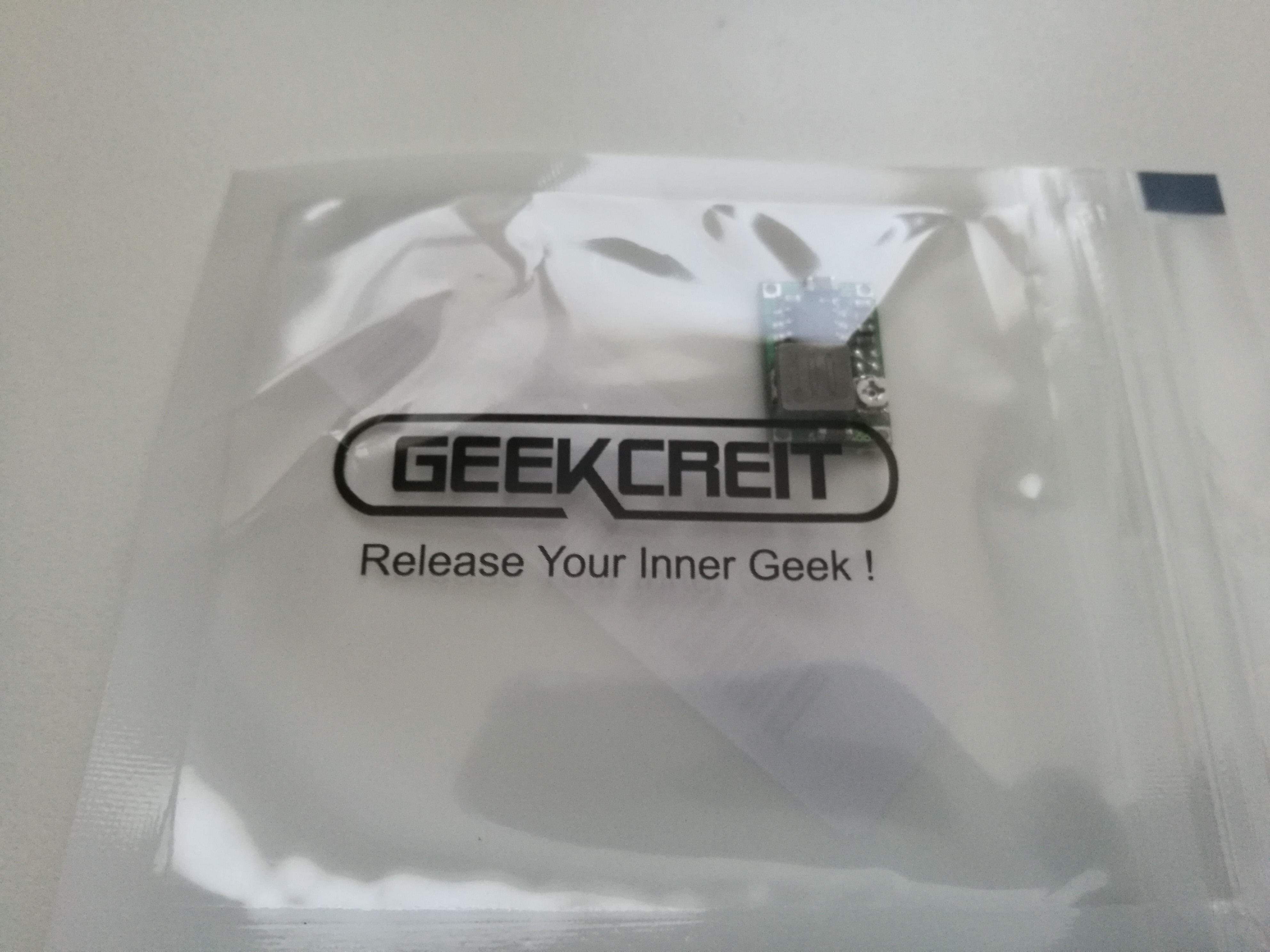
The PSU comes in small plastic bag:
Pro’s:
- cheap
- small (around size of TO220 IC package)
- adjustable
- much better efficiency than with linear regulator
Cons:
- very small voltage adjusting potentiometer
- there will be some amount of switcher noise on power output (depends on application of this matters or not)
Here are two videos that show why it is a good idea in many applications to use swithc mode power supply instead of traditional linear regulator:
#21 Voltage Conversion: Linear Voltage Regulator vs Buck Converter
Buck converter vs. linear voltage regulator – practical comparison
Back to details of my converter:
The circuit board is slightly bigger than TO220 case (around 10×20 mm)
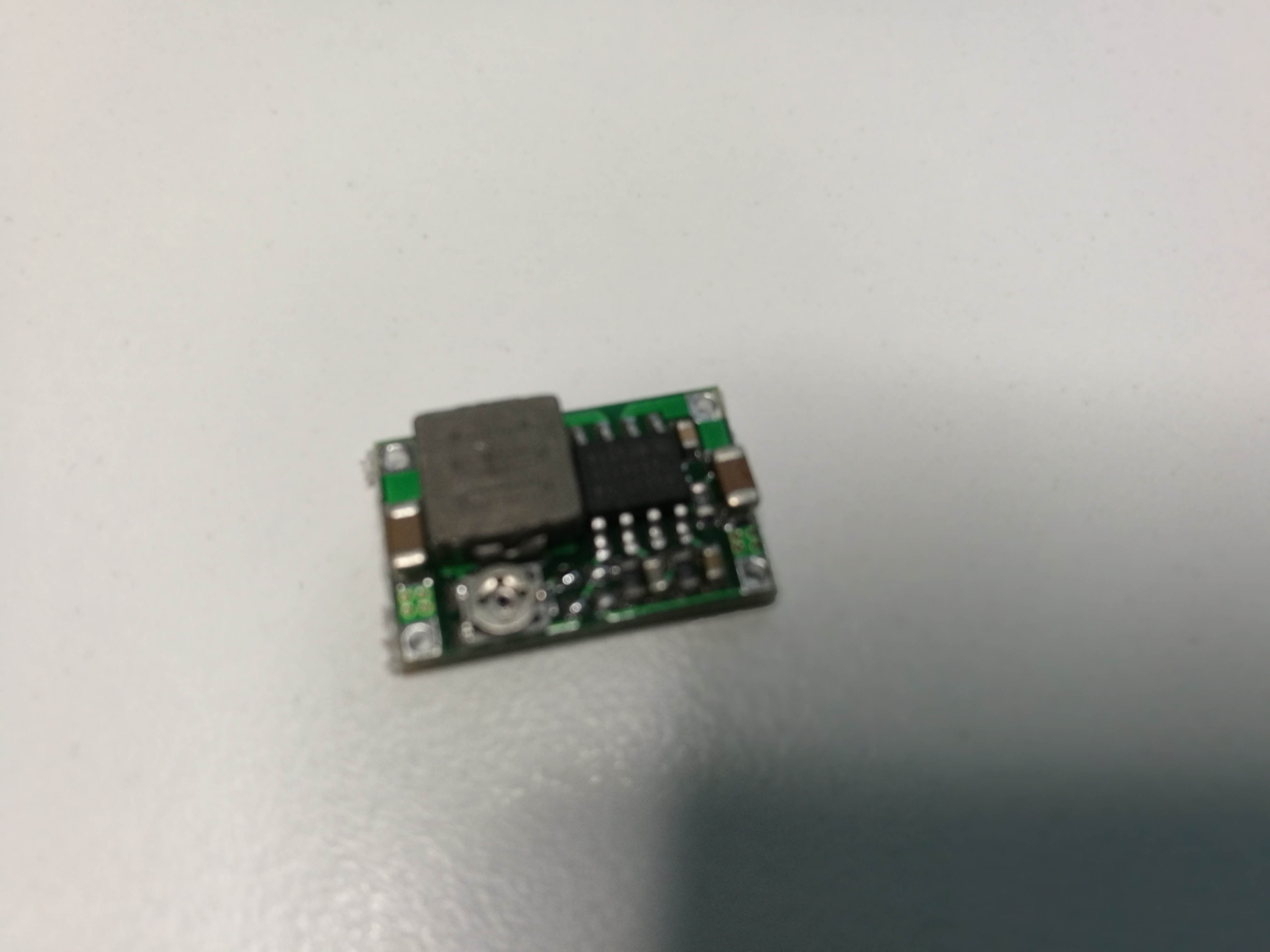
The converter is based onMPS MP2307 IC: The MP2307 is a monolithic synchronous buck regulator. The device integrates 100mΩ MOSFETS that provide 3A of continuous load current over a wide operating input voltage of 4.75V to 23V. For more details on control IC, take a look at MPS MP2307 product page and data sheet.
The implementation of the module seems to be pretty close to Evaluation board circuit and this example circuit rom EasyEDA web page:

Then next is circuit testing. My experiments with te modules I got were not promising. The first module I received seemed to generate promised prety clear output power, but tge the potentiometer could only adjust the output voltage from 1V to aroud 4.5V – it was promised on data that is should go higher.
Fortunately I had more units. The next unit coudl adjust the output voltage ant wide scale, but there was something strange on the output power: a lot of ripple in it. I measured around 500 mV RMS at 5V output with no load. The ripple was almost sinewave at around 100 KHz frequency (frequency changes somewhat depending on input voltage). Adding more input or output capacitance did not help much (I tried 100 uF low ESR electrolytic and smaller ceramic capacitors). Adding more load to outout did not considerably change the situation. It seems to be that there is something wrong…
The same happens also with several other modules, all giving 400 mV to 1V ripple on the outout. The modules also behave somewhat strange way when output voltage is set very near (or above) input voltage (output voltage drops and peaks). I also noticed that the output coil is getting hot even with no load – the modules take 50-70 mA current from 12V source even though there is no load on output.
This looks strange. I was suppoosed to have 340 kHz SMPSU, and not I get 100 kHz signal. According to datasheet, the regulator gors to 110 kHz output frequency on short circuit… but there was no short circuit at least on my connections.
I read some more comments on product page so I was that other people seem also to have similar issues:
- I’m NOT very satisfied because it gets very very hot and quickly. I use it in an application where I must supply 5V circuit (Arduino) from 13,8V (car) voltage. At cuurent consumption of ca. 60mA the gray chip gets hot as much as 60 deg Celsius (I have measured that) what means in closed enclosures can lead to fire.
- With 12V input and 3.3V output and no load, the idle current is 52mA. The inductor heats up quickly and hot to the touch. I tried other combination of input and output voltages and the results were the same. I ordered 5 of these and they are all the same. They are simply useless.
- I bought these to power my Eachine ProDVR but if I use them, the DVR recordings have way too much interference. I have tried moving it further away, putting a capacitor on the output and wrapping it in aluminium tape connected to ground (only helped a little). I’ve gone back to the LM7805 and the recordings are perfect.
There is also discussion on thebackshed forum on similar issues:
- I’m not impressed, and my own personal tests on these have resulted in me rejecting them as they seem to be either a bad design around the regulator chip, or just a bad regulator chip design in general.
- Datasheet says standby current should be 1.5mA max, but the no-load current of all the modules I tested(I have 10) are all about 75mA in standby with no load, and they get remarkably hot at that 75mA with no load, so I would be concerned about putting any REAL load on them.
- They are rated for 2A continuous, and 3A surge, but with 300mA on them, they are hot enough to roast a chicken. Not good. About 80′C so says the laser temp probe. Under about 500mA load, the temp goes up to about 95′C(holy cow!), and the output voltage dips from the set 7v down to about 6.2v which for a 3A rated regulator is pretty poor if it can’t maintain it’s output voltage under load – a load well within it’s specs if the datasheet is to be believed.
- If you look at a good datasheet for this sort of regulator you will see that the inductor has to be selected based on both the input voltage and the output current. It is impossible to design a circuit that will work efficiently over the ranges advertised.
The guys on this site have done a quick review/test on them as well DCDC-MINI360
Short Protection: This module can take some abuse too: when shorted, the input current went to 0.99A first and then slowly dropped to 0.3A as chip and inductor were heating up. After removing the short, the circuit worked as expected.
No-load Consumption: With input at 12V and output set to 5V, the module took 48mA without load. The 100uF/25V electrolytic capacitor lowered this to 21mA. With 47Ω output load, the input current was 82mA without 100uF, and 72mA with 100uF.
Other Notes: Built-in trim-pot is very sensitive and for fixed output applications we recommend to hold it’s position by drop of glue or cut it out and replace with fixed value resistor. See the MP2307 datasheet for the math. (MP2307 power mod video shows how the module can be modified to use fixed resistor instead of potentiometer. )
Conclusion: I would not recommend this module under 50mA load as linear regulator will do a better job in that range, but going over 50mA this regulator will work excellent. Also recommending additional electrolytic at least 100uF/25V at the input.
I can agree the comments above.
It seems that investing to5Pcs Mini DC Adjustable Power Supply Buck Module Step Down Module ws not the best idea. Maybe I need to get some better quality power modules next time.
Here are links to some similar small switch mode regulator modules (I don’t know of if they are better or worse):
8 Comments
Kiki says:
great
https://www.wikipedia.org/
Tomi Engdahl says:
The same switch mode power supply IC was used also in this module (and it works well):
Power supply module tested
http://www.epanorama.net/newepa/2016/04/11/power-supply-module-tested/
Jens says:
I just binned a dozen of them with the same issues (output coil getting hot and high current consumption even under no load conditions). Plus some boards had manufacturing defects. Make sure you test these before putting them into use!
Cris says:
Hi, I had the same problem. Much heat, hi current in idle state… But when I receive another lot, I have the surprise to find that all was ok, current in idle is 7-9 mA, not heat at all. Sorry I can not put some photo. The inductor in the new lot are different, they are clear marked “100″ (10uH). The old, which are heating, are unmarked. I think that when the inductors are bad, all will go wrong. I will change the inductors at the wrong ones.
Cris says:
… I changed the coil, and nothing is changed… With the osciloscope, I saw the line at the exit… was not the line. About 1V ripple, at 5V Vout. I put one 10uF ceramic smd above the one at the pcb, at exit, and….. the idle current dropped from 50 mA to 11 mA, the out line is next to flat, the heat is minimum. In the datasheet, it is required 2X22uF at Vout. And the board is fine.
Dale Schultz says:
I have also been finding terrible quality control on the MP2307 modules from China. Some drawing 34mA or even 43Ma with no load and getting very hot. Best result is one that draws 15mA by itself!
I was using them for lighting inside model train passenger cars, so the small size was very attractive.
Stephen says:
thanks, God Abbah YHWH bless you
Tomi Engdahl says:
With Just $0.50 Components I turned Garbage Products into GOLD!
https://www.youtube.com/watch?v=6bicunweBAQ
0:00 The Problem of my AliExpress Products
1:16 Intro
2:04 Why is Noise/Ripple Bad?
3:39 How to Measure Noise Correctly
4:32 5V UPS Noise Problem
5:46 Solution 1: Post Regulation
7:51 Solution 2: Component Improvement
8:39 Capacitor Replacement
9:55 Other Component Problems
10:49 Mini Boost Converter Fix