They are heavy (because of their iron core) and can be very large. The power transformers are design to operate best with an almost constant load which is equal to their rating. The maximum efficiency being designed to be at full load.
Actually, all the transformers are the same that is same design formulae apply for small signal transformers to the power transformers. In case of power transformers, the designer needs to consider: voltage, current, operation frequency (50 Hz or 60 Hz normally), resistances on the coil wires and to remember that heat will need to be dissipated without any part over-heating.
Transformer inrush current describes a spike in current that occurs when you initially turn on your transformer. This spike can be normally up to 10 times higher than normal current. Inrush current in a transformer can cause several problems. Not only does it interfere with the operation of circuits, but it could result in detrimental effects to the transformer. The distortion of the volt or current waveform, known as harmonics, is another side effect of inrush current. If not properly managed, inrush current could lead to failure of circuit components, shorten the operating life of the transformer, or even cause damage.
Understanding Transformers Part 1: Inrush, Saturation and Fusing
https://www.youtube.com/watch?v=x24545H5HdU
We test a transformer using a Rigol 1054z scope and a 120 volt transformer to see what current inrush we get due to saturation, and explain transformer characteristics and fusing considerations
Understanding Transformers Part 2: Developing a Simulation Model
https://www.youtube.com/watch?v=kNQRCTioyy4
We show how to develop a simulation model of an iron core transformer by bench testing and measuring, as well as by analyzing physical characteristics. We develop a linear model in LTSpice and also a nonlinear model, including saturation effects, and compare simulation results with oscilloscope bench tests.
Understanding Transformers Part 3: Improving the Transformer Model with Bench Testing
https://www.youtube.com/watch?v=cA6QKXwiZl8
We do some actual bench testing on our 120VAC transformer by applying up to 230VAC (using our Morphon variable transformer) and measuring the current flow using our Rigol DS1054Z oscilloscope and two multimeters. We then put that model into our transient simulator software (you can use LTSpice or Matlab & Simulink) to verify our model matches reality.
Transformer Inrush in 5 minutes
https://www.youtube.com/watch?v=xQ7KO_vQR0o
A brief description of transformer inrush.
What Is Inrush Current And Why Do I Care?
https://www.youtube.com/watch?v=2xIsmRkpQLA
Fluke Clamp Meters: What Is Inrush Current And Why Do I Care?
Featuring Fluke 370 Series and Fluke 381
Transformer Inrush Current: Limiting a 40VA Transformer
https://www.ametherm.com/blog/inrush-current/transformer-inrush-current-40va-transformer
48 Comments
Tomi Engdahl says:
01821 Workbench 101 #2 How does a Dim Bulb Current Limiter Work
https://www.youtube.com/watch?v=8lCRMJA7jTk
In the first part of the video I go over how a dim bulb current limiter works and why you do not want to make one out of resistors. In the second part I do some practical demos of how a dim bulb works, the amperage differing wattage of bulbs let in, the difference between dim bulbs in parallel vs series and how it acts as a limited surge suppressor.
Tomi Engdahl says:
01021 Workbench Safety 101 #1 Variac and Isolation Transformer Hookup
https://www.youtube.com/watch?v=XUxFGyNiyhI
Tomi Engdahl says:
Let’s Experiment with an Electromagnetic Chain!
https://www.youtube.com/watch?v=JbRLoWzHVEA
Have you ever seen an electromagnetic chain? Its a series of electric and magnetic toroid cores linked in the form of a chain transferring power from electricity to magnetism and back again as it works it way along the device. Its a great hands-on illustration of Maxwell’s equations as well as an illustration of transformer action taken to extremes.
Tomi Engdahl says:
https://www.facebook.com/groups/VintageElectronicTestEquipment/permalink/5626034367513709/
That’s a step down transformer.
Yes you can do it but need to exercise some precaution: The LV winding that was intended by design to be the secondary winding, will serves as the primary & the value of the magnetizing inrush current actually will be greater than expected. When a transformer is reverse fed, the taps move to the output side and so their operation is reversed. Taps will control the output voltage so chances of over excitation will be there. This is not serious concern till the input voltage variation is within limit. OC voltage of the winding which is supposed to be the secondary will be higher than the nominal voltage. This is to allow for the drop in the winding so that the nominal voltage will be present when the transformer is loaded fully. The degree of change in the secondary voltage is expressed as the transformer’s regulation; the lower the figure the better. Using the transformer in reverse you need to increase the applied voltage to the secondary which will act as primary when reverse fed.
Tomi Engdahl says:
Custom Coils has a good explanation of different core materials and their characteristics:
https://www.customcoils.com/blog/types-of-magnetic-core-materials-for-transformers/
Tomi Engdahl says:
https://www.custommag.com/r-core-transformers
http://jamestransformer.com/en/transformer/R_core_transformer.html
Tomi Engdahl says:
Advantages of toroidal vs EI and R-core transformers
Updated: Nov 8, 2021
Toroidal transformers – best choice for your audio application
https://www.mpaudio.net/post/advantages-toroidal-transformers#amp_tf=L%C3%A4hde%3A%20%251%24s&aoh=16809475341697&referrer=https%3A%2F%2Fwww.google.com&share=https%3A%2F%2Fwww.mpaudio.net%2Fpost%2Fadvantages-toroidal-transformers
Tomi Engdahl says:
https://www.carroll-meynell.com/transformer-parameters/
Tomi Engdahl says:
https://amgistoroids.com/resources/toroidal-technology/physical-size-vs-power-rating-table-amgis/
Tomi Engdahl says:
How do you reduce leakage inductance?
To minimize leakage inductance, the primary winding should be wound on a long bobbin, or tube, with the secondary wound as close as possible, using a minimum of insulation. Magnetic cores can have identical rating, but one core will provide a lower leakage inductance than the other.
Tomi Engdahl says:
What is the typical leakage inductance of a transformer?
Leakage Inductance
We can now see that LP and LS are in series between the primary voltage and any secondary load. A typical AC transformer might have 3% total leakage inductance compared to magnetization inductance, so if the total primary inductance is 1 henry, the leakage inductance will be around 30 mH.
https://resources.altium.com/p/transformer-theory-made-simple
Tomi Engdahl says:
Pulse transformer leakage inductance is amazingly low?
Posted by opampsmoker on 01 Oct, 2020 09:22
https://www.eevblog.com/forum/renewable-energy/pulse-transformer-leakage-inductance-is-amazingly-low/
Tomi Engdahl says:
https://www.customcoils.com/blog/how-to-build-a-good-toroidal-transformer/
https://onlinelibrary.wiley.com/doi/abs/10.1002/ecjb.4420680502
Tomi Engdahl says:
https://en.m.wikipedia.org/wiki/Toroidal_inductors_and_transformers
https://www.magtop.com/a-method-to-reduce-leakage-inductance-problem-of-toroidal-transformer.html
Tomi Engdahl says:
https://www.kritester.com/new/test-leakage-current-of-transformer.html
Tomi Engdahl says:
https://www.diyaudio.com/community/threads/how-much-clearance-around-a-toroidal-transformer.293094/
General rule: there is NO general rule! Noise can come from magnetic and electric coupling too.
Toroidal transformers have theoretically no outside leakage flux, if the winding is distributed perfectly evenly, and if during the winding process of each coil the core rotates 0 in sum. The latter condition is often not fulfilled, hence the toroid transformer can behave like a 1…5 turn air core coil. Depending on the winding details a toroid can be almost perfect or as bad as an EI. This “rotation coil” flux can be cancelled by an inversely rotating wire, if you can measure the induced voltage.
If the wire is not evenly distributed, it is also a source of outside flux. For this I don’t know simple remedy.
These fluxes decreases with distance, but since a tipical toroid main diameter is not very small, decreasing is not very fast, so avoiding interference by keeping clearance is not practical.
I suggest you to design a good layout instead, without ground loops, with symmetrical internal signal paths, signal and its reference wire as close to each other as possible. A good layout is not sensitive for magnetic disturbance.
Or you can simply measure the disturbance level around the transformer (under load!) with a probe coil and an amplifier.
Swapping the mains input phasing could have many subtle influences. So too can swapping the heater phasing (but not the mains side phasing). It would depend on what hum paths and asymmetries are significant. Sometimes a humdinger pot has no effect, and sometimes an asymmetrical setting is an improvement. For example, a mains side active wire is near enough to input circuitry to have an influence, and so changing that wire to a neutral wire causes a drop in hum.
Tomi Engdahl says:
https://en.wikipedia.org/wiki/Toroidal_inductors_and_transformers
Tomi Engdahl says:
https://www.physicsforums.com/threads/how-to-calculate-toroidal-core-maximum-va-capacity.876425/page-2
Tomi Engdahl says:
https://talema.com/introduction-to-toroidal-transformers/
https://www.noratel.com/products/toroidal-transformers/
Tomi Engdahl says:
https://www.quora.com/How-does-the-shape-of-a-transformer-change-its-properties-How-is-a-toroidal-transformer-different-from-a-regular-transformer
There is very little difference in practice. The toroidal transformer does carry a load of hype however.
If you wind a coil toroidally, in theory, there is no magnetic B flux outside the coil. This is desirable, especially when low EMI is required. The result depends on perfect radial symmetry (the environment looks the same no matter which radial line you look along) of the winding and the environment.
However, in practice, these coils are never wound toroidally. Instead, the winding starts with one turn at one point and then proceeds progressively adding the next turn to the side of the previous turn. The effect is that the transformer has many turns around the toroid core, but it also has one large turn around the circumference that readily couples to external circuits.
Also, any magnetic material that is not placed with radial symmetry will spoil the symmetry.
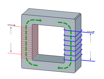
The basic idea of a transformer is transfer the maximum magnetic flux from Primary to Secondary, with as few losses as possible. Traditionally low frequency (mains or audio) transformers used sheets of steel as the former around which the coils are wound. They are cheap and quite efficient BUT bulky, heavy and not very smart.
There are many ways which the windings can be arranged and this will guide the shape of the product. In recent times it has become important to reduce size and weight so the toroidal or donut transformer became popular.[1]
The key thing is that the magnetic flux is concentrated in the ferrite ring with very little escaping into the air. This saves losses, reduces heat and allows very compact transformers to be designed. The downside is that special machines were needed to perform the winding operations.
So toroidal transformers or inductors are very efficient and compact. They beat the traditional heavy metal designs in many ways. The price has probably dropped since Chinese factories have been manufacturing these products. Everybody wants compact equipment and power efficiency is a big driver.
How does the shape of a transformer change its properties? How is a toroidal transformer different from a regular transformer?
The toroidal shape helps confine the magnetic field much better than the rectangular type. In fact original inductors and transformers were toroidal as the maths is cleaner. Unfortunately toroidal transformers need to be hand built or at least on a machine like a sewing machine. As the wire must be threaded around each time . The EI rectangular shape transformer can be built automatically and at high speed.
Tomi Engdahl says:
https://onlinelibrary.wiley.com/doi/abs/10.1002/ecjb.4420680502
Abstract
The effect of winding configuration on leakage inductance of a toroidal core transformer for electronic pulse-drive circuits is investigated. Theoretical expressions for the effect of wire diameter, conductor spacing of primary and secondary windings, winding pitch, number of turns and core dimensions are derived. It is found that: (1) winding capacitance can be reduced without increasing the leakage inductance by applying an insulation coating to the core; (2) the leakage inductance is simply proportional to the number of turns; (3) a core of square cross-section can reduce the ratio of leakage inductance to excitation inductance; (4) leakage inductance decreases with decreasing conductor spacing of the pair wire and with increasing diameter; (5) and the leakage inductance decreases with decreasing winding pitch and, in the case of a dense winding, it is less than that of a sparsely wound coil by as much as a value proportional to log (4/3). The experiments in which the above results were obtained were in good agreement with calculated values.
Tomi Engdahl says:
A method to reduce leakage inductance problem of toroidal transformer
https://www.magtop.com/a-method-to-reduce-leakage-inductance-problem-of-toroidal-transformer.html
The leakage inductance of the toroidal transformer = magnetic leakage. The greater the magnetic leakage, the worse the efficiency of the transformer. For example, the larger the magnetic leakage of the audio transformer, the sound quality will be affected. So the leakage inductance problem is also our concern. So how to reduce the leakage inductance problem of the transformer? The main reason for the magnetic leakage is that the magnetic flux of the iron core does not fully participate in the coupling between the primary and the secondary, and a small part forms a loop outside the iron core, so a large part of the magnetic leakage is The reason is because of the iron core. Therefore, in order to reduce the magnetic flux leakage problem, we must first start from the iron core.
We can know that the better the iron core material and the better the craftsmanship, the smaller the magnetic flux leakage and the higher the efficiency. Therefore, choosing high-quality iron core materials can reduce the magnetic flux leakage. Such as silicon steel sheet iron core material: silicon steel sheet is divided into b1 super material, b1 material, B1 material, B4 material, B4 material, A material, H material, the thinner the thickness of the silicon steel sheet, the better the core quality.
When the iron core is fixed, other parameters are also fixed. The size and cross-sectional area of the iron core are no problem, and its magnetic permeability will not be too high. At this time, it is necessary to increase the number of turns of the primary coil to meet the requirements of the transformer for the inductance, but the number of turns of the coil is proportional to the leakage inductance, and the leakage inductance of the coil will increase accordingly. So we need to reduce the frequency to reduce the leakage inductance, which can be reduced to 35~40Hz.
The relative position and interval between the primary and the secondary will also produce magnetic flux leakage, so to reduce the magnetic flux leakage, the primary and secondary coils should be wound evenly and evenly on the core.
Tomi Engdahl says:
https://www.mdpi.com/1996-1073/15/17/6176
Conclusions
In this paper, a single-phase toroidal transformer was discussed in the 2D ANSYS Maxwell platform. The aim was to study the effect of different design configurations on leakage inductance. For this purpose, different toroidal transformers were designed and various parameters, such as magnetic flux density, magnetic field strength and leakage inductance were discussed. The leakage inductance is a small fraction of the magnetizing inductance, but it can be significant in transformers with a high number of turns operating at high frequency. It was observed that minimizing the distance between the core and the winding caused leakage inductance to decrease. Another factor that affected the leakage inductance was the overlapping of windings. Leakage inductance obtained through simulation was similar to the analytical results, which validated the precision and reliability of the analysis. Since transformers are usually symmetrical, the results of 2D modeling in FEA were accurate and the time consumption was considerably less than multiple prototyping, manufacturing and measurement. More accuracy in analytical and simulated values can be achieved by decreasing the size of segments and increasing the number of meshes at the cost of increased computational time. High-frequency toroid used in DAB was further validated with the help of experimental prototypes.
Tomi Engdahl says:
https://www.traftor.com/blog/ressource/toroidal-inductors-and-transformers-advantage-leakage-flux/
Tomi Engdahl says:
https://hackaday.com/2023/10/09/learning-about-ferroresonant-transformers-while-fixing-a-1970s-power-supply/
Tomi Engdahl says:
https://www.electrician-1.com/2021/02/transformer-definition-and-working.html#google_vignette
Tomi Engdahl says:
neon xformers are typically called xx-xx. The first two X’s means the secondary voltage. The last two indicate the output current. Sign type units come in currents of 30, 60, and occasionally 120mA. Voltages are 4(800), 6(000), 75(00), 9(000), 12(000) and 15(000). Ergo a 9-30 would be 9kV at 30ma. Furnace ignition transformers can be spotted by the output current of 20mA. Usually 10kV.
Tomi Engdahl says:
https://hackaday.com/2024/02/15/electrical-steel-the-material-at-heart-of-the-grid/
Tomi Engdahl says:
https://hackaday.com/2024/02/14/parts-we-miss-the-mains-transformer/
Tomi Engdahl says:
Why ferrite core is not used in low-frequency?
Short answer: Ferrite core can be used in high frequency as it has a low area of hysteresis and it also has very high resistance so laminating the core is not required. But these are not preferred in low frequency operation because they are easily saturated as they are known as ‘hard magnetic material’
Tomi Engdahl says:
https://www.quora.com/Is-use-of-a-ferrite-core-more-efficient-than-an-iron-core-in-a-transformer-when-the-core-is-not-saturated-Given-that-you-can-set-the-frequency
What is difference between ferrite core transformer and simple transformer?
Short answer: Ferrite core can be used in high frequency as it has a low area of hysteresis and it also has very high resistance so laminating the core is not required. But these are not preferred in low frequency operation because they are easily saturated as they are known as ‘hard magnetic material’.
Detailed answer: This question must be answered from the point of view of BH curve or hysteresis. For one cycle of operation, the area of BH curve signifies the hysteresis loss in the concerned magnetic material for that cycle. Now for very high frequency operation there is more number of cycles in a second. Now the hysteresis loss becomes very high.
Hence, the core which is used in power transformers of 50Hz, if used for 100kHz of operation the hysteresis loss becomes 2000 times more. To address this issue ferrite core is used which has very small area of hysteresis. In the below image the black one is the ferrite core and the blue is the silicon-steel.
Hence you can easily understand that ferrite will have very low loss compared to silicon still in high frequency.
Moreover, they have a very high resistance so they can inherently reduce eddy current losses without resorting to lamination. In addition, being a very brittle material, lamination of ferrite is very impractical. It will break if it drops from your hand. (I have broken a few accidentally!)
In spite of all the advantages, Ferrite cannot be used in low frequency because, Ferrite is a ‘hard magnetic material’ while silicon steel is a ‘soft magnetic material’. What do I mean by hard magnetic material can be understood in simple terms like ‘the ability to go in saturation’. If you see the image, the blue curve can go deep in saturation than the black. Now all low frequency machines are designed for a bit of saturation. If in these machines, a hard material is used it will draw crazy amount of current every time the machine goes to a little saturation which is inevitable by its design. Moreover, the size issue, cost and brittleness are other hindering problems.
Tomi Engdahl says:
https://en.m.wikipedia.org/wiki/Ferrite_core
Tomi Engdahl says:
https://www.kgs-ind.com/products/emc/ferrite-core/low-frequency/
Tomi Engdahl says:
https://electronics.stackexchange.com/questions/117281/what-is-the-low-frequency-limit-for-ferrite-cores-in-audio-applications
What is the low frequency limit for ferrite cores in audio applications?
I’ve searched high and low through the ferrite magnetics catalogs and this list for an answer and can’t find data on ferrite core permeability below 10kHz. My application is for audio use and I need to know how the permeability of the core drops off with falling frequency.
Ideally the permeability will drop rapidly at 300Hz, with some flexibility in the frequency. I imagine core losses will be small in this region since a lower permeability results in lower hysteresis losses. Also I suspect the core air gap will not play much of a role.
4
μi
should not change much from DC to 10kHz, that’s why the graphs will typically only show frequencies above 10kHz, for MnZn ferrites, for example.
Materials such as permalloy have noticeably lower permeability at 100Hz than at DC.
There is no low frequency limit – I’m running 6.0 Hz through a ferrite transformer in order to provide signal isolation to a circuit. I can run it all the way up to 50 kHz too and, there is no change in amplitude.
What I have to be aware of is the low magnetization inductance that a hundred turns on an RM12 pot core produces. This, of course affects the lower frequencies much more hence, the overall low permeability of ferrites means that I can’t reliably use them as 50/60 Hz AC mains transformers.
So, running them at 6.0 Hz means I cannot transfer watts of power so easily.
You have to be aware of core saturation. The RM12 (3C90 material) pot core that I wound had 100 turns but only had a primary inductance of 56mH. So, at (say) 50Hz, this is an impedance of about 18 ohms. With 3C90 material, looking at the BH curve for the material, it “starts” to saturate at a magnetization (H) of about ~50 ampere turns per metre: -
What does that mean you might ask! The “/m” part is the effective length of the ferrite core i.e. the distance the magnetism “travels” around the core and for an RM12 this is about 57mm so, the number of ampere turns you can apply is 50 * 0.057 = 2.85 ampere turns. As I have 100 turns, this means the pot core will start to saturate at a current of 28.5 mA peak.
The RMS will be about 20mA – given the impedance at 50 Hz is only 18 ohms means a terminal voltage limit of about 0.36V RMS. At 1kHz, the impedance will be 20 times higher and therefore you can apply 7.2V RMS to the transformer before saturation starts to be seen.
So, ferrites have no low frequency limit providing you avoid saturation.
Tomi Engdahl says:
Quiz : explain why pulse transformer can be 1/10 ( or smaller ( size from conventional 50 Hz transformer ?
50hz transformers need a lot of inductance and that needs a lot of iron and copper. Pulse transformers, quite high frequency and low power need low inductance, only requiring smaller windings generally on a small ferrite core.
Magnetic core materials and coil inductances required at 50Hz and 50kHz are very different
You can use , for example, ferrite for the core and far fewer turns at 50kHz
frequency affects the size even for sinewave transformers. A transformer with same core material that is designed to work at 400 Hz is much smaller that another one that works from 50 Hz to 400 Hz.
Higher frequency = smaller. Lower power = smaller.
I guess the best way to describe is the closer you get to DC the more the inductor (coil) looks like a piece of wire . Low resistance. As frequency increases the coil starts to look like an open circuit .
I wish I had my books with me I would give you the equations . I believe XL= 1/ 2pi f . Basically as frequency goes up , inductance goes down .
Franjo Trninić 80-120 kilo
.and does the freq..affect the size ?
Shimon David in most power supply topologies the transformer core needs to be able to store at least the energy of one pulse of electrical power that is fed to the transformer primary. The energy depends on time (set by frequency) and current. Current depends on primary inductance and frequency. At higher frequency less inductance and energy storage is needed – so smaller core and less copper turns, so smaller transformer.
Tomi Engdahl says:
Depends on size. Basically related to wattage. A 50 Hz pulse transform will be the same size as 50Hz conventional sinewave transformer for the same wattage load. If a “pulse” transformer is smaller then it is either or both a different wattage or a different magnetic material.
Tomi Engdahl says:
How 3 Phase Transformers Work – why we need them
https://www.youtube.com/watch?v=u0SsejDCVkU
Tomi Engdahl says:
What is a Transformer? Transformers Explained – Working Principle (Transformer Tutorial)
https://www.youtube.com/watch?v=yaQ2aWv86uY
Tomi Engdahl says:
https://zilogbob.com/blue2_ringer/blue2_ringer.htm
This new ring tester can test pretty-much all common inductors
including low-frequency mains and tube audio transformers
for shorted turns. At last it is available from EVB in Portugal.
Tomi Engdahl says:
From my personal experience (>25years of repairs) – embedded fuses are the best thing to prevent fire!!! I newer saw this fuse blown without real reason or in normal use. Yes, this is annoying, but if you do not want to have burning house replace them with new ones.
You’re wright, the should be forbidden…
The problem is when a divice gets warm during normal use, and you switch off and on, they blow up…
Tomi Engdahl says:
Erwin van Amelsfoort that’s a design problem in equipment design. Typically slightly undersized transformer and/or poor thermal design of the device.
Those built-in fuses in transformer are good safety protection against fire danger. Separate fuse gets often changed to wrong bigger current size by user if they fail.
Tomi Engdahl says:
Open-Circuit and Short-Circuit Tests in Transformers
A transformer could be tested under no-load and full-load conditions to determine its turns ratio, regulation, and efficiency. However, without fully loading the transformer, it is possible to perform two tests (open-circuit and short-circuit) from which all the important data can be derived. In this article, learn how to analyze the results of open-circuit and short-circuit transformer tests to determine the component values of the transformer equivalent circuit.
https://eepower.com/technical-articles/open-circuit-and-short-circuit-tests-in-transformers/
Tomi Engdahl says:
https://www.canwindg.com/a-news-demystifying-the-various-transformer-core-shapes
Tomi Engdahl says:
https://www.eevblog.com/forum/projects/what-core-alloys-are-most-typical-in-audio-and-power-(5060hz)-transformers/
Tomi Engdahl says:
https://shinenergy.net/guide-to-transformer-core-types-materials-and-applications/
Tomi Engdahl says:
https://electronics.stackexchange.com/questions/301032/characteristics-of-ferrite-cores
Tomi Engdahl says:
What are distribution transformers?
Distribution transformers are electrical devices that step down medium voltage (like 11kV) to low voltage levels (like 400/230V) for safe and efficient use in homes, businesses, and industries. They’re the final stage in the power distribution network, playing a crucial role in supplying electricity to end-users. These transformers typically have a primary winding in a delta configuration and a secondary winding in a star configuration, allowing for both 3-phase and 1-phase power supply.
Tomi Engdahl says:
toroidal transformers tend take higher startup current on primary side when powered on than EI transformers. There are two things that cause the surge:
1. initial core magnetizing current
2. Small transformer losses (resistance, leakage inductance)
The 1 can burn primary fuse but does not affect the bridge rectifier.
The 2 causes high current flowing through rectifier on device starting, and cause rectifier failure if power supply was not properly engineered in the beginning (or the original transformer has been changed to different type).