I found a cheap mixed signal oscilloscope product: HT-USBee AxPro. This HT-USBee AxPro is a said to be 8 Channel Logic Analyzer Oscilloscope Compatible USBee AX Pro I2C IIC SPI CAN Debugger. It features Oscilloscope Input (single channel, 16Msps, 3MHz bandwidth) and 8-CH Logic Analyzer. With suitable software it can be used as Data Recorder, Voltmeter, Mixed Signal Oscilloscope and Logic Analyzer, Frequency Meter, Remote Controller, PWM Controller, Frequency Generator, I2C Controller and Pulse / Edge Counter.
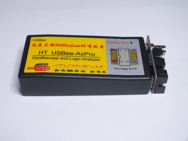
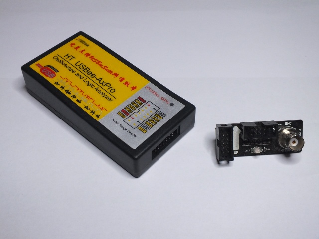
HT-USBee AxPro seems to be well built. The product is supplied with an adapter that allows connecting oscilloscope probe easily. The oscilloscope input is designed for +-10V signals and logic probe channels are suitable for normal TTL(5V)/LVTTL(3.3V) signal levels. The adapter pinout for digital seems to be same as used on other similar product: digital signals wired straight through and other signals left out.
The product does not come with any software or documentation. The comment on HT-USBee AxPro page tells that to get it working you need to go to usbee.com download page and get there USBee AX (Standard, Plus and Pro) software+drivers before connecting the device to computer. I already had drivers installed in my PC from an earlier test. In addition to drivers I had also had USB suite installed.
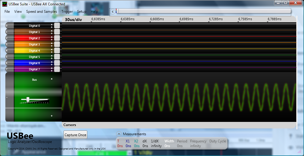
I found that USBEE Suite and USBEE AX software package worked well. For individual testing of different functions the USBEE AX programs worked well. For mixed signal work where you capture the data and look it afterwards, USBEE Suite is the best choice. It allows to view oscilloscope and logic signals on the same time scale, which is excellent for debugging embedded systems where there is both digital and analog signals.
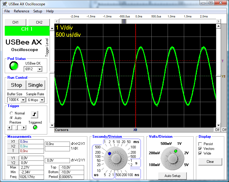
For real time oscilloscope view the USBee AX Oscilloscope is the best choice. It provides traditional real time oscilloscope view to signals.
There was also signal generation tools, and they all worked well…
One thing I noticed when doing analogue measurement (oscilloscope, voltage meter), that there was 10% measurement error on the measurements I had: the computer showed around 10% higher values than the real voltage. That but it could be fixed by doing pretty simple calibration procedure as told at http://dreamland227.blogspot.fi/2011_10_01_archive.html.
A product review would not be complete without seeing what what is inside. Here is a view on the circuit board inside the device:
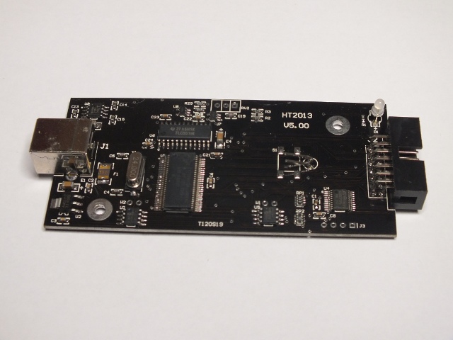
The main component are Cypress CY7CS8013A controller and TLC5510 (8-Bit, 20 MSPS ADC Single Ch., Internal S&H, Low Power). Logic probe pins seem to be directly wired to controller pins without any protection or other components there (different approach than in another USBEE AX clone).
This product is pretty clearly a clone product. Have in mind that buying USBee Test Pod clones is not something CWAV condones. If you have doubts in using this product with software from CWAV (the maker of USBee products), there is an alternative free open source software available at http://sigrok.org/. Although there is free software support for logic analyzer part of it in sigrok developers aren’t really excited with USBee AX Pro clones so support for analog channels is missing.
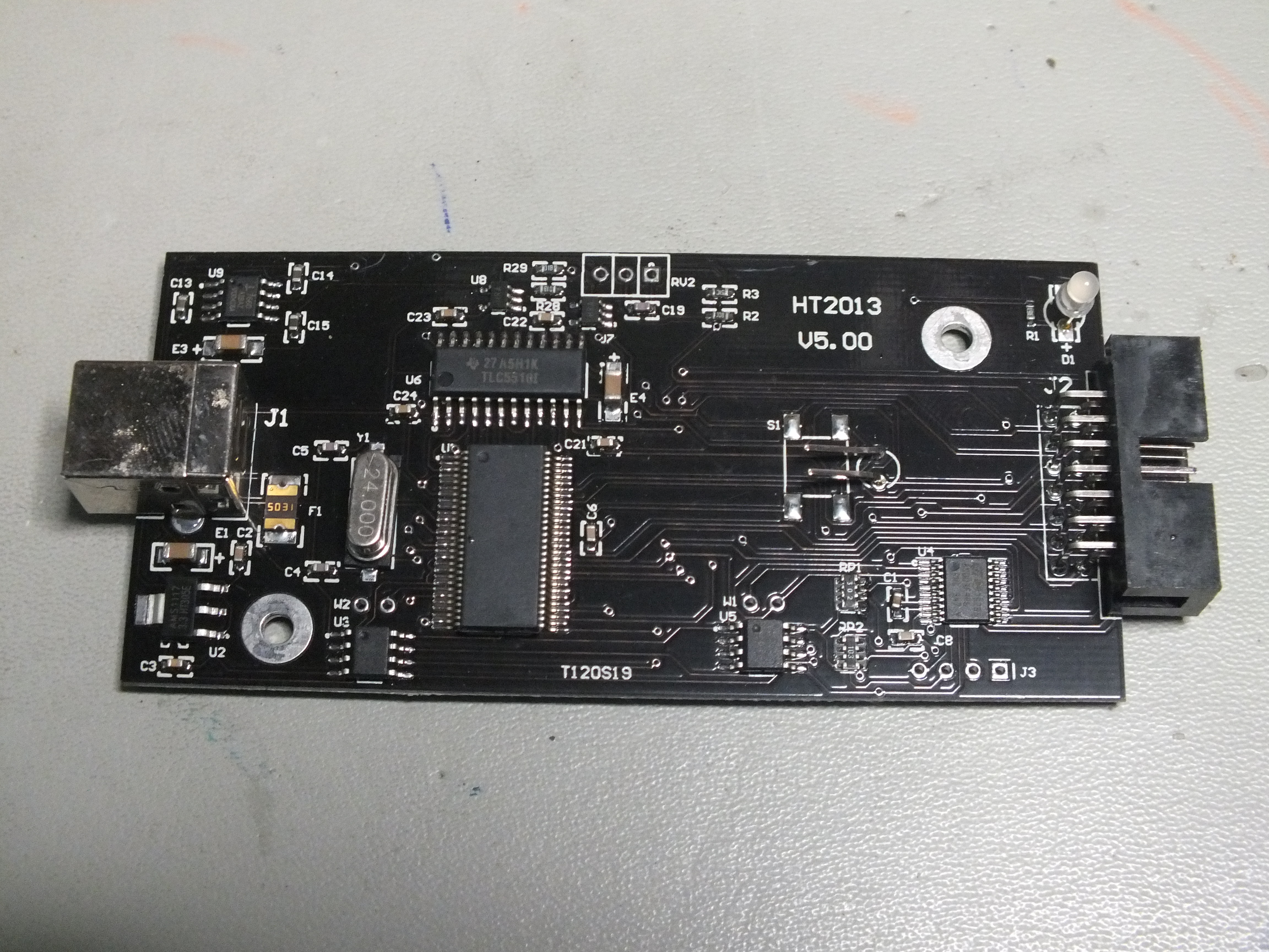
Late addition: More detailed higher resolution circuit board view (click to enlarge):
22 Comments
Tomi Engdahl says:
MSOs probe analog and digital
http://edn.com/design/test-and-measurement/4429600/MSOs-probe-analog-and-digital
Many microcontroller-based systems have both analog and digital signals. Even those that appear to be entirely digital aren’t because of analog effects such as ringing and crosstalk. Thus, you often need both analog and digital views of your system’s signals. That’s where an MSO (mixed-signal oscilloscope can help.
MSOs incorporate the functionality of both an oscilloscope and a subset of capabilities found in logic analyzer. The most common MSO configuration has four analog channels and 16 digital channels. MSOs find their greatest applicability in troubleshooting embedded microprocessor boards.
Carlos says:
Hello
G
As stated by almost all reviewers, because it is a clone, the original software designers took advantage of one of it’s design flaw (EEPROM not write protected), leading to an erased memory => “Device not recognized” (see forums below). Thus I recommend that, before you even connect it for the first time to your PC, to cut the EEPROM’s 7th pin and connect to it’s 8th one, enabling it’s hadware read-only operation, bypassing any erors with even the latest software version.
Carlos says:
Hi I read this on a different clone, this also has this problem
Tomi Engdahl says:
Sounds like an interesting modification idea…
MysticDarkLord says:
Hello G,
Does cutting the 7th pin and connecting it to the 8th pin work if you have unwittingly connected it to your computer already. Obviously the drivers are not installed, and USBee website is charging $20 fore the USBee Suite and drivers for the AxPro. Is there a way around this other than using the third party software, which I read from Tomi is not very good?
Cheers
Juan M. says:
Entiendo el que hay que proteger la EPROM, pero alguien me puede decir cual de las dos que lleva es? la U3 o la U5,
Gracias anticipadas.
Tomi Engdahl says:
It seems that due USBEE AX clones he original manufacturer seems to have changed things so that you have to pay for USBEE AX drivers to get then from the manufacturer. Check http://www.usbee.com/usbeeqxarinc429module-1-1.aspx
Maybe this is the answer to the clones… When there is a lot of cheap hardware clones, try to sell the software for this instead of your own expensive hardware…
Tomi Engdahl says:
AX pro driver
http://www.drivermax.com/driver-download/0/USB+Universal+Serial+Bus/CWAV/USBee+AX-Pro
jfmateos says:
Does the signal generator work with this clone?
Tomi Engdahl says:
Yes!
The signal generator application works well this AX Pro clone.
Serge says:
Tomi, can you provide better images of the circuit board especially of U4 chip and the area around it? I bought a same device, but this chip is not populated on the circuit board. I’m guessing the purpose of this chip.
Tomi Engdahl says:
I will try to find more detailed picture or take a new close-up on the circuit board….
Tomi Engdahl says:
Now I added a new higher resolution picture to to end of the posting (click to enlarge).
Tomi Engdahl says:
That chip U4 in my circuit board is STMicroelectronics 8s003f3p6 8-bit Microcontroller
Serge says:
Thank you, Tomi. Unfortunately, my device does not operate properly :(. Analog readings are completely off (9,92V by measuring all above 4,5 V), the analog waveform is the same as digital one.
Sun21 says:
2Serge: I have the same device as you: also no U4 and U5 chips.
Voltage is 3 times higher and input resistance=33k on analog input !!!
I added 68k resistor in series and I can calibrate the device and have right measurement on analog channel.
I tested all applications that come with driver, seems work well. But when I tryed to use Generator (output) and Oscilloscope (input) apps at the same time I got BSOD.
Sun21 says:
2Serge: in addition to prev. comment: on the board I removed R2 that have _wrong_ value 67ohm (smd label: 80X) and soldered normal (not smd) 68k (smd label would be 80C) into the middle and right holes of RV2.
Now calibration and measurement on the analog channel looks OK. Input R=100k
Ted says:
Analog readings completely off. ..
Analog input in ADC (TLC5510I) is pin 19. Range for ADC chip is fixed from 0v (pin 23 REFB) volts to 3.3v(pin 17 REFT). Se datasheet.
3.3v are from output of converter ds1117.
Two op.amps. AD8065 (marked HRA) are for buffering and level conversion with the help of R2,R3 and R28,R29.This op.amsp are connected to +5 and -5v. The -5volts are from 7660 DC converter.
If Va is Analog input from probe. We have:
Vo1 (out of op.amp.U7) = Va x R3 / (R2+R3)
Vo (out of op.amp. U8) = (Vo1 + 3.3)/2 (as the two R28 and R29 are both 1k). This output is connected to pin 19 of ADC.
I see R28=R29=102 = 1k. R3 is 51C = 33.2k, and R2 is 67ohms. And as Sun21 says it is wrong value!
With the wrong value of R2 (67 ohms) we have a -3.3 to 3.3v range…
Changing R2 to 67k we have the expected range from -10 to 10v, for a 0 to 255 counts (8 bit resolution)
and also 100k input impedance !
BSOD: Apps cannot run at the same time on this cypress chip…
Spa Elixir says:
Hi mates, how is all, and what you would like to say
about this article, in my view its truly amazing for me.
Vicky says:
It’s really a great and helpful piece of info. I am satisfied that you simply shared this useful info with us.
Please stay us up to date like this. Thank you for sharing.
Enrgtech says:
The article is much informative which i was searching for .Nice intro good explanation thanks for sharing.
Tomi Engdahl says:
https://sigrok.org/wiki/HT_USBee-AxPro