I got interested interested in ESP8266 WiFi module after reading New Chip Alert: The ESP8266 WiFi Module (It’s $5) article. Why is it cool? It’s a WiFi module with an SOC, making it somewhat similar to TI’s CC300. ESP8266 is an UART to WiFi module that you can pick for less than $5 USD.
ESP8266 is a really cheap and easy way to connect any small microcontroller platform (for example Arduino) wirelessly to Internet. The microcontroller on the module takes care of all the WiFi, TCP/IP stack, and the overhead found in an 802.11 network. It’s addressable over SPI and UART, making this an exceptionally easy choice for anyone wanting to build an Internet of Things thing. You can use AT commands to connecyt to WiFi networks and open TCP connections without need to have TCP/IP stack running in your own microcontroller: You can simply connect any microcontroller to this module and start pushing data up to the Internet. This might be why it seems that ESP8266 has pretty soon become every hacker’s favorite WiFi chip.
The ESP826 module I bought from Electrodragon is simple having only the ESP8266 IC and one other IC in it. The WiFi antenna is integrated to circuit board. The whole module is just size of post stamp.
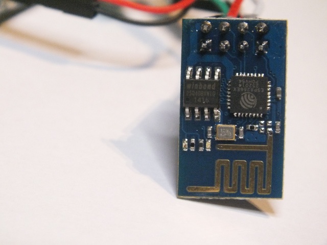
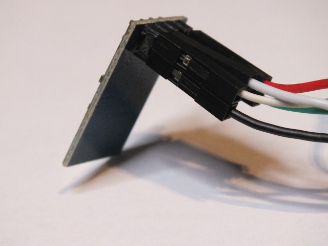
The other side of the he module des not have any components, just 8 pins I have attached wires to in this picture.
There’s a catch, right, there’s always a catch on the cheap products. One thing is that ESP8266 pretty much doesn’t exist outside China. Ordering from China is not a problem nowdays, but when all the documentation is in Chinese, that can be a problem. But fortunately there has been projects to get ESP8266 translated data sheet.
I had enough information, so I need to get one module to test. I ended up ordering ESP8266 module from Electrodragon (check module data). ESP8266 from Banggood.com would have been cheaper bit taken longer time to get because ESP8266 module was listed to out of stock at the time.
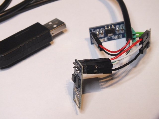
The module and IO pins run at 3.3V. For testing I used USB To RS232/TTL PL2303HX Cable Adapter and 5V to 3.3V regulator module to do the connection. I used separate 3,.3V regulator module because I wanted to guarantee that the module can get enough current (over 200 mA on peaks) (some other USB-serial adapter ICs have 3.3V regulators built in them but can’t give enough current out). Wi07c ESP8266 module data and different project examples got me started pretty well.
Test commands at 115200-N-8-1 serial port settings:
AT+RST
AT+CWMODE=1
AT+CWJAP=”SSID”,”PASS”
AT+CWJAP=”AndroidAP”,”XXXX”
AT+CIPSTART=”TCP”,”www.epanorama.net”,80
AT+CIPSEND=0,n: Where n is the length of the request string.
AT+CIPCLOSE
The results with those were promising. Wiring ESP8266 to your favorite microcontroller platform has pretty much everything you would need to do with an Internet of Things thing. That’s good enough, but things are even better.
It has turned out that it is possible to do run your own coode on the module itself: An SDK for the ESP8266 WiFi Chip turns the ESP8266 into something much better than a UART to WiFi module; now you can create a Internet of Things thing with just $5 in hardware. You can write the software using C programming language and GCC compiler to processor in the module (80MHz Tensilica). Included in the SDK are sources for an SSL, JSON, and lwIP library, making this a solution for pretty much everything you would need to do with an Internet of Things thing. Looks interesting, I just have to find time to test that out…
Review articles on ESP8266
First impression on the ESP8266 serial-to-WiFi module
The Current State of ESP8266 Development
Review on the new and cheap esp8266 WiFi module – video
The Current State of ESP8266 Development
Sites on ESP8266 information:
translation of the datasheet and AT command set
Project pages:
Using the ESP8266 module
A Development Board for the ESP8266
ESP8266 and PL2303HX-gpio adventures
Update Firmware ESP8266Cloud Update - also video
A Proof of Concept Project for the ESP8266
The ESP8266 Becomes a Terrible Browser
ESP8266 Retro Browser – Accessing a web site with an ESP8266 serial WiFi module and an Arduino Mega
Keep an Eye on Your Fermenting Beer with BrewMonitor
An ESP8266 Based Smartmeter
Checking Email With The ESP8266 – reads the subject and sender lines from the latest email and displays it on an LCD
ESP8266 Wifi Temperature Logger – using the ESP8266 and Arduino to update a remote Thingspeak server
Adding wifi to a desk lamp with the Wi07C (ESP8266)
Places to order:
ESP8266 module from Electrodragon
SDK:
An SDK for the ESP8266 WiFi Chip
The ESP8266 SDK is finally here – along with a VirtualBox image with Ubuntu that includes GCC for the LX106 core
Source code examples:
331 Comments
Tomi Engdahl says:
IOT based Voice Controlled Home Automation using ESP8266 and Android App
https://circuitdigest.com/microcontroller-projects/iot-based-voice-controlled-home-automation-using-esp8266
Welcome to another exciting Project in which we will build a Voice Controlled Home Automation System using ESP8266 Wi-Fi module, where you can control your Home AC appliances using your Voice though an Android App from anywhere in the world. Yes, your dream of making your loads (Light/Fans) to turn ON or OFF by simply using a voice command is going to come true at the end of this project.
Just like in the previous project we are going to program our ESP8266 module with the help of the Arduino IDE. There is a slight modification made in the program. This modification is made so that your ESP8266 connects to a constant IP address every time it establishes a connection with the Router.
Port Forwarding your ESP8266 IP:
The first step is to enable Port forwarding in your router (modem) so that you can access your ESP from anywhere in the world, just by entering your public IP. Whenever our ESP8266 connects to our home/office router it will be given a Unique IP address and this IP Address is used to access the ESP8266 through web browser. This IP address is restricted within your Home/Office Network, meaning you can’t access it globally; it can only be accessed by devices that are connected to your router. Port forwarding is the Technique through which we can make this webpage load globally. After port forwarding you can use your public IP to access this webpage from anywhere in the world. Sounds cool right!! Let see how we can get this done. To do this you know the following beforehand.
1. The manufacturer name and IP address of your Router. This can be easily found by looking at the router. The IP address will also be mentioned on a sticker. If not Google to know your Routers IP.
2. The username and password of your routers login page. Most routers will have user name as “admin” and password as “admin”.
3. The IP address allocated to your ESP8266 module. This is the address that you use to access the webpage of the ESP module.
4. The IP address of your Internet service provider (public IP address). This can be found by simply Goggling “what is my IP”.
Creating Applets using IFTTT service:
We are one step away from completing this project. The last step is to create the Applets in the IFTTT website. This is where we instruct our Moni for different voice commands to control different Home appliances at home.
uniquetees.us says:
The art has been designed. I have a relationship with the printer, who has printed quite a few other runs
of shirts for me.
Tomi Engdahl says:
Garage Door Opener Logs to Google Drive
https://hackaday.com/2017/01/15/garage-door-opener-logs-to-google-drive/
A garage door opener is a pretty classic hack around these parts. IR, Bluetooth, WiFi, smartphone controlled, web interfaces — we’ve seen it all. But if you want to keep track of people going in and out, you need some way of logging what’s happening. You could go ahead and roll up your own SQL based solution, tied into a custom web page. But there’s an easier way; you can build a garage door opener that logs events to Google Drive.
[WhiskeyTangoHotel] was looking for an ESP8266 project, and a garage door opener seemed just the ticket. It’s simple enough to code up, and control over WiFi comes in handy. Interfacing with the garage door was simple enough — the existing opener uses a simple push button, which is easily controlled by wiring up a relay to do the job. Logging is as simple as having the ESP8266 send requests to IFTTT which is set up to make posts to a Google Sheet with status updates.
The project is fairly basic, but there’s room for expansion. By using separate Maker Channel triggers on IFTTT, different users of the garage door could be tracked.
ESP8266 WiFi Garage Door Opener from any Web Browser
http://www.whiskeytangohotel.com/2017/01/esp8266-wifi-garage-door-opener-from.html
Tomi Engdahl says:
BBSing with the ESP8266
http://hackaday.com/2017/06/17/bbsing-with-the-esp8266/
Modems have been around for longer than the web, and before we had Facebook we had the BBS scene. Somewhat surprisingly, people are still hosting BBSes, but have fun finding a landline these days. [Blake Patterson] is one of the leading aficionados of retocomputers, and recently he took it upon himself to review an interesting new device. It’s the WiFi232 Internet Modem, a device that turns a WiFi connection into something a computer with a 25-pin RS-232 connector can understand.
The WiFi232 is made by [Paul Rickards], and given the last few years of WiFi-enabled retrocomputing projects, it’s exactly what you would expect. Onboard the WiFi232 is an ESP8266 module emulating the Hayes AT command set. Baud rates from 300 to 115200 are supported, with power provided through a USB mini jack or solder terminals.
The Wonderful WiFi232: BBSing Has (Literally) Never Been Easier
http://www.bytecellar.com/2017/05/30/the-wonderful-wifi232-bbsing-has-literally-never-been-easier/
Over the past year or so, I’ve been loading up SyncTerm and logging in to various telnet-accessible BBSs here and there — nothing too consistent
Paul’s WiFi232 Internet Modem is an inexpensive device that lets you BBS the way it was meant to be done, on hardware from the golden age of the Bulletin Board System.
In a nutshell, it works like this: The WiFi232, as far as your vintage computer is concerned, is a Hayes telephone modem. It accepts standard AT commands as well as AT commands that go rather beyond the standard Hayes commandset. The purpose of the device is to act as a bridge between your serial port and your local WiFi router. It has a 25-pin RS-232 data interface and a Mini-USB connector for power — it should work with any computer sporting a standard serial port.
Tomi Engdahl says:
Practical IoT Cryptography on the Espressif ESP8266
http://hackaday.com/2017/06/20/practical-iot-cryptography-on-the-espressif-esp8266/
The Espressif ESP8266 chipset makes three-dollar ‘Internet of Things’ development boards an economic reality. According to the popular automatic firmware-building site nodeMCU-builds, in the last 60 days there have been 13,341 custom firmware builds for that platform. Of those, only 19% have SSL support, and 10% include the cryptography module.
We’re often critical of the lack of security in the IoT sector, and frequently cover botnets and other attacks, but will we hold our projects to the same standards we demand? Will we stop at identifying the problem, or can we be part of the solution?
This article will focus on applying AES encryption and hash authorization functions to the MQTT protocol using the popular ESP8266 chip running NodeMCU firmware. Our purpose is not to provide a copy/paste panacea, but to go through the process step by step, identifying challenges and solutions along the way.
MQTT is a lightweight messaging protocol that runs on top of TCP/IP and is frequently used for IoT projects. Client devices subscribe or publish to topics (e.g. sensors/temperature/kitchen), and these messages are relayed by an MQTT broker.
The MQTT protocol doesn’t have any built-in security features beyond username/password authentication, so it’s common to encrypt and authenticate across a network with SSL. However, SSL can be rather demanding for the ESP8266 and when enabled, you’re left with much less memory for your application. As a lightweight alternative, you can encrypt only the data payload being sent, and use a session ID and hash function for authentication.
A straightforward way to do this is using Lua and the NodeMCU Crypto module, which includes support for the AES algorithm in CBC mode as well as the HMAC hash function. Using AES encryption correctly requires three things to produce ciphertext: a message, a key, and an initialization vector (IV). Messages and keys are straightforward concepts, but the initialization vector is worth some discussion.
IVs make pattern analysis more difficult. An IV is a piece of data sent along with the key that modifies the end ciphertext result. As the name suggests, it initializes the state of the encryption algorithm before the data enters. The IV needs to be different for each message sent so that repeated data encrypts into different ciphertext
https://giachevrolet.com/ says:
I do trust all of the ideas you have presented on your post.
They are very convincing and will definitely work. Still, the posts are too quick for starters.
Could you please extend them a bit from next time?
Thank you for the post.
Tomi Engdahl says:
Nerd-Bait: ESP8266 + ILI9341 Screen
https://hackaday.com/2016/08/17/nerd-bait-esp8266-ili9341-screen/
And so it is with [Johan Kanflo]’s latest bit of work: a PCB that mounts an ESP8266 module onto the back of an ILI9341 color display, with user button, power supply, and an auxiliary MOSFET. Four bucks for the screen, four bucks for the ESP8266 module, and a few bucks here and there on parts and PCB, and you’ve got an Internet-enabled, full-color, 320×240 graphical display. That’s pretty awesome, and it’s entirely consistent with Elliot’s Law.
The Commadorable 64
https://johan.kanflo.com/the-commadorable-64/
Tomi Engdahl says:
Stalk Your Cats With A Browser-Controlled Robot
http://hackaday.com/2017/07/06/stalk-your-cats-with-a-browser-controlled-robot/
WiDC – Wi-Fi Controlled FPV Robot (with Arduino, ESP8266 and DC Motors)
http://www.instructables.com/id/WiDC-Wi-Fi-Controlled-FPV-Robot-with-Arduino-ESP82/
Tomi Engdahl says:
Talking To A Lamp
http://hackaday.com/2017/07/22/talking-to-a-lamp/
Barking commands at furniture seems a bit odd but with voice controlled home automation platforms becoming the norm, you may be spending more time talking to your light fixtures than your kids. In one such project, [Becky Stern] used an Alexa Dot and an ESP8266 respond to voice commands.
The design uses the Alexa Dot to interpret voice commands such as ‘Alexa turn the light ON’. The ESP8266 with a relay feather wing is used to switch the actual lamp ON and OFF. The glue between the two is the fauxmoESP library that allows the ESP8266 to receive commands from the Alexa API.
Smart Lamp With ESP8266 & Amazon Echo
http://www.instructables.com/id/Smart-Lamp-With-ESP8266-Amazon-Echo/
This Instructable guides you along with me in upgrading a vintage lamp with voice-control using an ESP8266 microntroller and Amazon Echo/Alexa. The Arduino code emulates a Belkin WeMo device using the fauxmoESP library, which makes setup a breeze.
https://bitbucket.org/xoseperez/fauxmoesp
Tomi Engdahl says:
Hackaday Prize Entry: Don’t Build This
http://hackaday.com/2017/07/24/hackaday-prize-entry-dont-build-this/
The ESP8266 is a remarkable piece of hardware. What we originally thought — and what was originally marketed as — a simple UART to WiFi bridge with Hayes modem commands has turned into one of the best embedded platforms around. It’s a powerful little microcontroller, it has WiFi, and it can send raw frames. That last bit is awesome, because it allows for some mischief or mirth making, depending on your point of view.
For his Hackaday Prize entry, [Tejas] is building a WiFi Jammer with an ESP8266. It’s a small device that is able to disconnect anyone from a WiFi AP. Should you build it? No. Can you? Sure, why not.
Wifi Hacking using ESP8266
Based on
NodeMCU ESP8266 Lua multi-mode WiFi hacking kit
https://hackaday.io/project/20072-wifi-hacking-using-esp8266
Tomi Engdahl says:
Programing ESPcopter – ESP8266 Drone with Visuino
Visually Programing ESPcopter – ESP8266 based programmable Drone with Visuino
https://hackaday.io/project/25687-programing-espcopter-esp8266-drone-with-visuino
ESPcopter is a really cool, ESP8266 based programmable Drone currently on Indiegogo:https://www.indiegogo.com/projects/espcopter#/ The drone is expandable, and has GPIO pins for connecting extra sensors and actuators.Visuino is an easy to use Graphical Software Development tool, and is perfect for easy programming of robots and drones.The goal of the project is to find the best way to program the ESPcopter drones with Visuino and to unlock the full ESPcopter potential, as a single drone, or even as a swarm of drones.
Tomi Engdahl says:
Quick Robin! The Bat Keychain!
http://hackaday.com/2017/08/09/quick-robin-the-bat-keychain/
We don’t know if Batman has a keychain for the keys to the Bat mobile, the Bat copter, and all his other vehicles. But we are guessing if he did, it didn’t look like the one [krishnan793] picked up cheap. It had a little button that lit up some LEDs and played a little tune. [Krishnan] thought he could do better with an ESP8266. After chopping up some headphones and adding a LiPo battery, he wound up with an improved key chain
Batman Keychain With ESP8266
http://www.instructables.com/id/Batman-Keychain-With-ESP8266/
Things needed.
ESP8266 01
3.7 V LiPo Battery
USB LiPo Charger
Old earphone speaker
LEDs
220 resistor
Tomi Engdahl says:
Want to Simplify the Connected World? Enter this IoT Development Contest and Show ‘em What you Got
https://www.eeweb.com/blog/nicole_digiose/want-to-simplify-the-connected-world-enter-this-iot-development-contest-and
If you’re a part of today’s connected world (which I’m assuming you are, since you’re reading this), you know that the Internet of Things (IoT) has been an explosive hot topic in recent years. Unfortunately, IoT development and prototyping cycles are long and expensive due to the time and complexity it takes to build even a simple IoT prototype. But fear not, because the creation of IoT projects doesn’t have to be difficult or time-consuming, and that’s what the world’s first ESP8266 IoT contest is all about.
Three innovative organizations — myDevices, SparkFun, and Espressif — have partnered to present the world’s first ESP8266 IoT contest. Espressif Systems produces the ESP8266 chip; SparkFun is a leader in open-source hardware, providing components, kits, and tutorials to speed up prototyping and make electronics more accessible; and myDevices created Cayenne, the world’s first drag-and-drop IoT project builder, which aims to simplify the connected world. With the help of these forward-thinkers, this contest will be a rewarding experience for all who participate.
So be prepared to show off how you use the ESP8266 to simplify the connected world. There’s no project too big or too small. You can create an automated garden, monitor the temperature in a room, or put your Raspberry Pi to use in a smart home project – it’s all up to you.
Entering this contest is easy and free. Just sign up for your free Cayenne account, create your IoT project using at least one ESP8266 board/module, and submit your project to the contest.
Jumpstart ESP8266 Projects with Cayenne
https://mydevices.com/cayenne/landing/jumpstart-esp8266-projects-cayenne/
Create web and mobile dashboards for ESP8266 projects
Drag and drop widgets to create a customized project dashboard
Add and remotely control sensors, motors, actuators, and more
Create widgets for any connected sensor or actuator
Create triggers and threshold alerts for devices, events, and actions
Schedule one-time or multi-device events for easy automation
Quick and easy setup – connect your projects in minutes
Tomi Engdahl says:
ESP8266 controlled stretch limousine
IoT solution to control the interior of a stretch limousine
https://hackaday.io/project/26879-esp8266-controlled-stretch-limousine
Our Solution fulfills the following requirements:
control via touch screens with modern GUI
2nd touch screen for the driver
communication of all components via WiFi
rugged design
simple to extend
We’ve used the ESP8266 – especially the Wemos D1 mini – for our solution.
Details
control via touch screens with modern GUI
2nd touch screen for the driver
communication of all components via WiFi
rugged design
simple to extend
Tomi Engdahl says:
LAMEBOY – another ESP12 handheld
fully portable ESP12 project with battery charging and power muxing
https://hackaday.io/project/26823-lameboy-another-esp12-handheld
View Gallery
3
20
16
Team (1)
davedarko
Join this project’s team
hardware
ongoing project
attiny ESP12 ESP8266 Grove i2c PCF8574 TSP2113 MCP73831 CH340G game boy gameboy wemos
This project was created on 08/15/2017 and last updated 3 hours ago.
Description
Ever since https://hackaday.io/project/18648-nokia-3310-5110-display-board I’ve wanted to slap on an ESP module and some buttons to make a nice little portable handheld. Now with some googling and checking out other projects how they get their stuff done and a bit time on hand while on vacation I’m using every spare minute to work on this PCB. There are some minor things I’m not sure about that need testing, but the general concept is clear.
Tomi Engdahl says:
ESP8266 Based Internet Radio Receiver is Packed with Features
http://hackaday.com/2017/08/22/esp8266-based-internet-radio-receiver-is-packed-with-features/
Have a beautiful antique radio that’s beyond repair? This ESP8266 based Internet radio by [Edzelf] would be an excellent starting point to get it running again, as an alternative to a Raspberry-Pi based design. The basic premise is straightforward: an ESP8266 handles the connection to an Internet radio station of your choice, and a VS1053 codec module decodes the stream to produce an audio signal (which will require some form of amplification afterwards).
Internet radio based on Esp8266 and VS1053.
https://github.com/Edzelf/Esp-radio
Tomi Engdahl says:
Keeping old equipment alive
http://www.edn.com/electronics-blogs/test-voices/4458758/Keeping-old-equipment-alive
De-soldering the 100 µF filter cap and checking it with an ohmmeter told the whole story; it wasn’t a capacitor anymore. Then I thought, “Oh heck, I don’t have any parts, I recycled them in New York.” I could have looked online and ordered a replacement but I wanted to get this repair finished that day if possible.
Fifty cents bought me a replacement capacitor; but, I spent an hour in the store, more reminiscing than shopping. Then I was on my way marveling at how things go in circles.
https://hackaday.io/project/26823-lameboy-another-esp12-handheld
With the capacitor replaced, the power supply worked like a charm and I had my oscillator back. I also had a new place to shop with my grandson for science project components.
Tomi Engdahl says:
Elderly Autonomous Fall Detection
https://hackaday.io/project/26983-elderly-autonomous-fall-detection
For only $10, sense if a senior citizen falls and be alerted, or they could just press a button to send an alert as well.
The 2017 Hackaday Prize
View Gallery
0
2
0
Team (1)
having11
Join this project’s team
Thingiverse
completed project
hardware
2017HackadayPrize mpu6050 ESP8266 iot Cayenne alert elderly senior fall detect Life
This project is submitted for
The 2017 Hackaday Prize
Assistive Technology
This project was created on 08/26/2017 and last updated an hour ago.
Description
This device can sense a fall and send a text or email to anyone you wish- a caregiver, loved one, or friend. There is also the option of pressing a button to alert whomever you want. In the case that someone is knocked unconscious from a fall and can’t press a button, they would still be able to receive help. This device uses an ESP8266, MPU6050, and MyDevice’s Cayenne IoT service to bring increased security and quality of life to senior citizens.
Tomi Engdahl says:
New Part Day: Pluggable ESP Modules
https://hackaday.com/2017/09/01/new-part-day-pluggable-esp-modules/
Almost exactly four years ago, we came across a really neat module for sale on SeeedStudios. It was a $5 WiFi chip, able to connect your microcontroller project to the Internet with just a handful of wires and a few AT commands. This was the ESP8266, and it has since spawned an entire ecosystem of connected devices.
Now, there’s a new version of the ESP8266 that simply showed up on the Seeed website. Officially, it’s called the, ‘ESP8285 01M Wi-Fi SoC Module’, but you might as well start calling it ‘the Pluggable ESP module’. It’s the smallest ESP8266 module yet at 18mm square, and this one is designed to be plugged into a card-edge connector. It’s eighteen pins of wonder and 1MB of Flash, all ready to be stuffed into the next Internet of Things Thing.
https://www.seeedstudio.com/ESP8285-01M-Wi-Fi-SoC-Module-p-2931.html
ESP-01M can be widely used in various occasions for networking, home automation, industrial wireless control, baby monitors, wearable electronics, infinite position sensing device, wireless positioning system, signal and other networking applications, networking applications is the ideal solution.
ESP-01M uses the DIP plug-in package, the unique design, so that it can be flexible docking to existing products, especially suitable for automation, large-scale, modern production of low cost, convenient application in various networking hardware terminal applications.
Tomi Engdahl says:
Hackaday Prize Entry: Elderly Autonomous Fall Detection
https://hackaday.com/2017/09/04/hackaday-prize-entry-elderly-autonomous-fall-detection/
The device uses an ESP8266, a MPU6050 MEMS gyro-accelerometer combo, and MyDevices Cayenne IoT service. The Cayenne IoT service is free for Makers and non-commercial use at the moment. The only other components needed are a few discretes and a small LiPo battery, keeping the cost of the device under $10. The whole assembly is housed in a 3D printed enclosure.
https://hackaday.io/project/26983-elderly-autonomous-fall-detection
Tomi Engdahl says:
Hackaday Prize Entry: Inexpensive Emergency Button
https://hackaday.com/2017/09/24/hackaday-prize-entry-inexpensive-emergency-button/
I’ve fallen and I can’t get up. We all remember it, and we all know what product we’re talking about. Now, with cheap microcontrollers, ubiquitous WiFi, and wearable electronics, there must be a simpler solution. [Jean Paradedel]’s emergency button project is designed to replace those wearable emergency buttons, which usually include an expensive call center plan.
[Jean]’s button is based off an ESP8266 module, which sends an email to a care provider if a button is pressed. The whole thing is powered by a CR2032 watch battery and the device’s case was 3D printed. The interface is simple — it’s just a wearable button, after all — and the form factor is small enough to be completely unobtrusive.
Emergency button : Reliable, Inexpensive & Design
Emergency Button for 7$ based on ESP8266 Wifi board
https://hackaday.io/project/27017-emergency-button-reliable-inexpensive-design
One of the main problems for old age people is keeping their balance while walking. It is getting more and more difficult to move, and if they fall down it’s very complicated to get back up. My family is calling my grandmother every evening to check for this kind of problem. There are some emergency buttons that can help, but you often have an expensive monthly payment for the call center. In addition, most old people don’t like to wear some gray plastic technologies around their neck.
Tomi Engdahl says:
Datalogger uses ESP32 and ESP8266 Low Power Modes
https://hackaday.com/2017/09/24/datalogger-uses-esp32-and-esp8266-low-power-modes/
[G6EJD] wanted to design a low power datalogger and decided to look at the power consumption of an ESP32 versus an ESP8266. You can see the video results below.
Of course, anytime someone does a power test, you have to wonder if there were any tricks or changes that would have made a big difference. However, the relative data is interesting (even though you could posit situations where even those results would be misleading). You should watch the videos, but the bottom line was a 3000 mAh battery provided 315 days of run time for the ESP8266 and 213 days with the ESP32.
Tomi Engdahl says:
Channel-Attack-ESP8266
Channel-Attack with ESP8266
https://hackaday.io/project/27432-channel-attack-esp8266
Channel-Attack # deauthentication Attack.
While hackers do good most of the time, we occasionally do evil and pl
Channel-Attack with ESP8266
Channel Attack-not-deauthentication Attack.
http://github.com/vuong244/Channel-Attack-ESP8266
While hackers do good most of the time, we occasionally do evil and play a prank. The ESP8266, unlike JSON, allows me to do evil. Thus, I programmed the microcontroller for an evil purpose: slow down the WiFi.
Packet from a station is always addressed toward the access point, even if its destination is another station. The access point then relays the packet either via a wired interface, or wirelessly toward the recipient station. The two transmissions (from station to access point, and from access point to recipient station) can choose speeds independently.
Tomi Engdahl says:
Trouble Flashing Your ESP8266? Meet DIO and QIO
https://hackaday.com/2017/10/01/trouble-flashing-your-esp8266-meet-dio-and-qio/
It turns out that there are different types of flash used with the ESP8266, and the correct programming mode must be selected for a given hardware setup. These modes are known as DIO and QIO, meaning “dual IO” and “quad IO” respectively. This refers to the number of IO line used to talk to the flash memory. There are also further modes, known as DOUT and QOUT. It’s important to identify the modes supported by the flash chip on board, by looking at the datasheet. Obviously this can be difficult on some pre-built modules, so experimentation is the key here.
Tomi Engdahl says:
iDONT (Internet Doorbell ON/off Trigger)
iDon’t as in I don’t want my doorbell to ring.
https://hackaday.io/project/20545-idont-internet-doorbell-onoff-trigger
Using an ESP8266, two relays, five ICs, and some R and Cs, the iDONT is placed between the doorbell transformer and existing wiring to the doorbell and chimes. The iDONT not only silences the doorbell on command from a smart phone, but sends a message when the doorbell is pressed even when the chimes are off!
Tomi Engdahl says:
Eavesdropping With An ESP8266
https://hackaday.com/2017/11/02/eavesdropping-with-an-esp8266/
In the old days, spies eavesdropped on each other using analog radio bugs. These days, everything’s in the cloud. [Sebastian] from [Hacking Beaver] wondered if he could make a WiFi bug that was small and cheap besides. Enter the ESP8266 and some programming wizardry.
[Sebastian] is using a NodeMCU but suggests that it could be pared down to any ESP8266 board — with similar cuts made to the rest of the electronics — but has this working as a proof of concept. A PIC 18 MCU samples the audio data from a microphone at 10 kHz with an 8-bit resolution, dumping it into a 512-byte buffer. Once that fills, a GPIO pin is pulled down and the ESP8266 sends the data to a waiting TCP server over the WiFi which either records or plays the audio in real-time.
Voice over WI-FI with ESP8266
http://hackingbeaver.com/?p=957
Tomi Engdahl says:
Alexa, Hack My TV
https://hackaday.com/2017/11/12/alexa-hack-my-tv/
If you have an Alexa, one of the best things you can buy to go with it is a Harmony Hub remote. Sure, you get a universal remote to control all your home theater equipment, but you’ll hardly use it because the Alexa can virtually push the Harmony buttons for you. The negative word in this paragraph, though, is “buy.” The Harmony Hub isn’t inexpensive. Fortunately [Michael Higginis] has you covered. He has an ESP8266 universal remote that you can control with Alexa
On the one hand, the idea is fairly simple. An ESP8266 has plenty of horsepower to read and recreate IR codes. However, we were very impressed with the web portal used to configure the device and integrating it with Alexa is a neat trick.
Unlike a real Harmony Hub, however, the remote only controls IR devices. However, since the Alexa to device connection is WiFi, you probably won’t miss having an RF remote, even if you need to tuck the remote away in an enclosure somewhere.
ESP8266 Compatible IR Blaster that accepts HTTP commands for use with services like Amazon Echo
https://github.com/mdhiggins/ESP8266-HTTP-IR-Blaster/
Tomi Engdahl says:
Weather Station Needs Almost No Batteries
https://hackaday.com/2017/11/13/weather-station-needs-almost-no-batteries/
While the ESP8266 has made its way into virtually every situation where a low-cost WiFi solution is needed, it’s not known as being a low-power solution due to the amount of energy it takes to run WiFi. [Alex] took this design constraint as more of a challenge though, and with the help of an ATtiny microcontroller was able to develop a weather station using an ESP8266 that only needs new batteries every 2-4 years.
ESP8266 on batteries for years – part 1
https://www.cron.dk/esp8266-on-batteries-for-years-part-1/
For some time I have been fascinated by the possibilities of the ESP8266, but I never really considered it good for a life on batteries. I got an idea of making an outdoor weather station that would send measured light level, temperature and humidity to my home automation server.
The ESP is a hungry beast when it’s doing WiFi. According to different sources on the internet it uses about 70 mA on average when WiFi is on! This would mean that I have to change batteries on my sensor quite some times every year.
I instead came up with the idea of a design using an AtTiny85 for doing frequent measurements and then once in a while to wake up the ESP beast to transmit it’s recorded data to the server.
Tomi Engdahl says:
ESP-12 SOCKET ADAPTER SOLDERLESS FLASHER
https://hackaday.io/project/28439-esp-12-socket-adapter-solderless-flasher
I believe that just like me, many of you have already had to flash a firmware to the ESP-12 before soldering it on a pcb. So I made a video showing how I solved this problem.
https://www.youtube.com/watch?v=vXDHyCQ3suw
Tomi Engdahl says:
Minimizing ESP8266 Battery Drain
https://hackaday.com/2017/12/03/minimizing-esp8266-battery-drain/
[Alex Jensen] wanted to build a battery-powered weather station, using an ESP8266 breakout board to connect to WiFi. However, [Alex]’s research revealed that the ESP chip uses around 70mA per hour when the radio is on — meaning that he’d have to change batteries a lot more than he wanted to. He really wanted a low power rig such that he’d only have to change batteries every 2 years on a pair of AAs.
The two considerations would be, how often does the ESP get powered up for data transmissions — and how often the weather station’s ATtiny85 takes sensor readings. Waking up the ESP from sleep mode takes about 16mA — plus, once awake it takes about 3 seconds to reconnect, precious time at 70mA. However, by using a static IP address he was able to pare that down to half a second, with one more second to do the actual data transmission. In addition to the hourly WiFi connection, the Tiny85 must be powered, though its relatively modest 1.5mA per hour doesn’t amount to much, even with the chip awake for 36 hours during the year. All told, the various components came to around 500 mAh per year, so using a pair of AA batteries should keep the rig going for years.
ESP8266 on batteries for years – part 1
https://www.cron.dk/esp8266-on-batteries-for-years-part-1/