I had earlier built Original Hiland DIY M12864 Graphics Version LCR ESR PWM Transistor Tester Kit and used it successfully. The kit worked well, but on longer term use I felt that the lack of proper case for it was sometimes annoying. I had some time though if making my own case, but it felt a quite of work to make a case with right kind of hole for ZIF (zero insertion force) test connector.
Then one day I saw Original Hiland Supporting Shell For DIY M12864 Graphics Version Transistor Tester Module Case on sale and decided to buy it. After few weeks of waiting I received the package with the following parts in it.
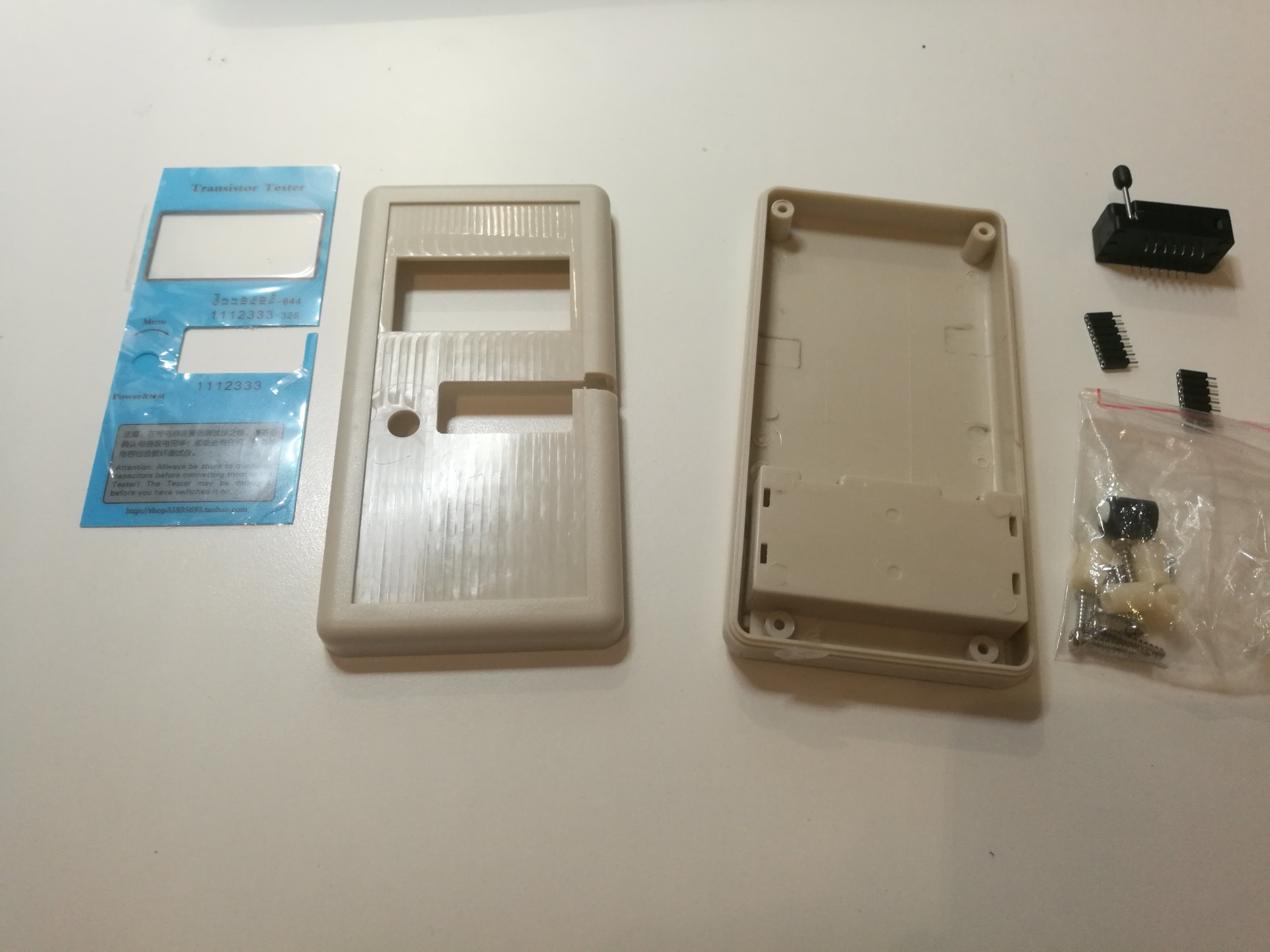
It was everything I needed to put this circuit into the case.
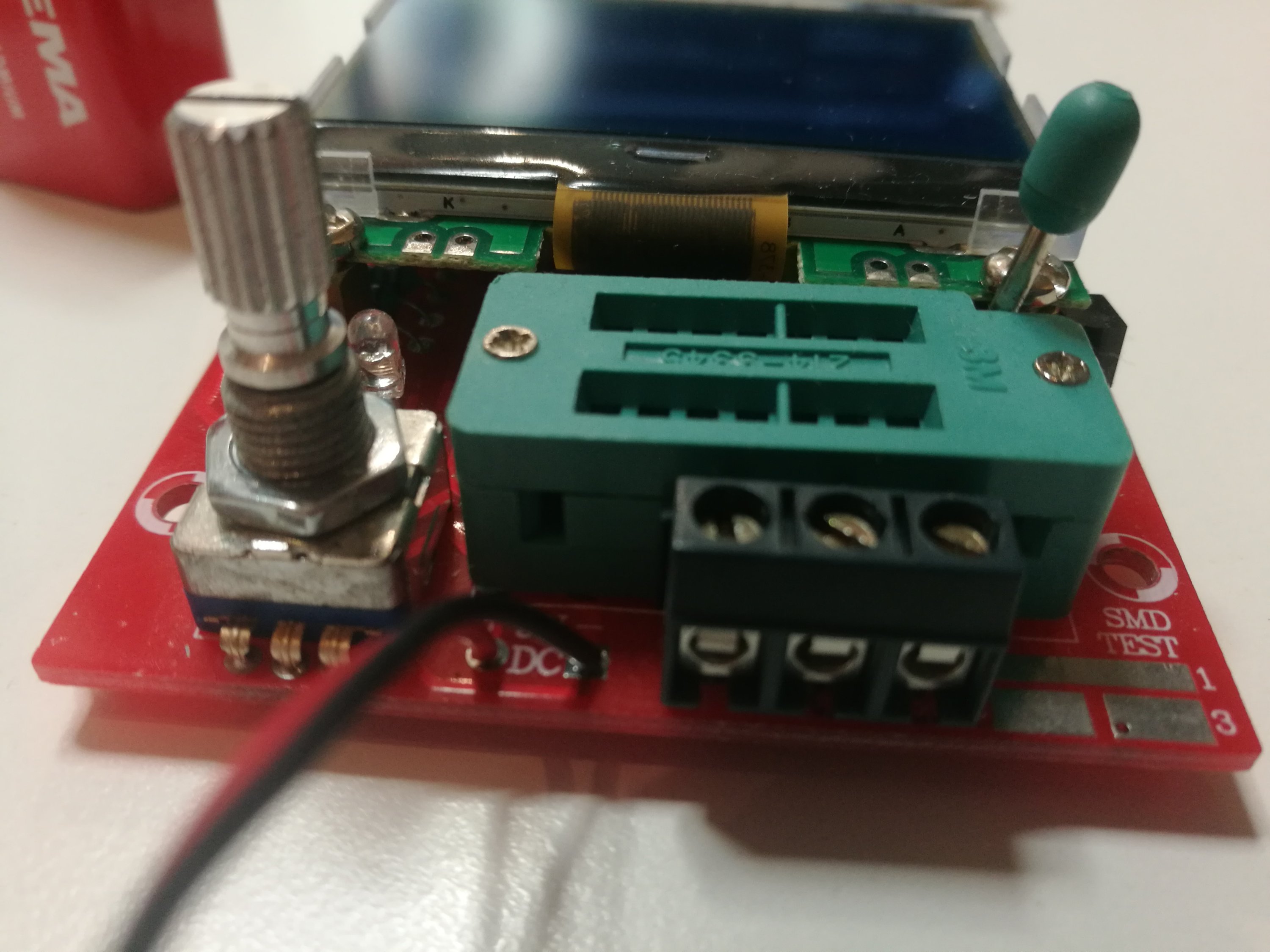
The task of placing the circuit inside the case takes more than just dropping the circuit board inside the case. The issue here was that the original ZIF connector was soldered directly to the board, while the case was designed so that the ZIF should be raised from the board. So I needed to remove the old connector from the circuit board – de-soldering it was reasonable effort with my de-soldering iron that had built-in solder sucking pump.
The case kit came with a new ZIF connector and needed socket adapters to raise it up from board as needed. The soldering was an easy task.
After that the it was just matter of placing the board in side the case and tightening the screws. There was one set of screws to hold the circuit board on the front panel and other to close the case itself.
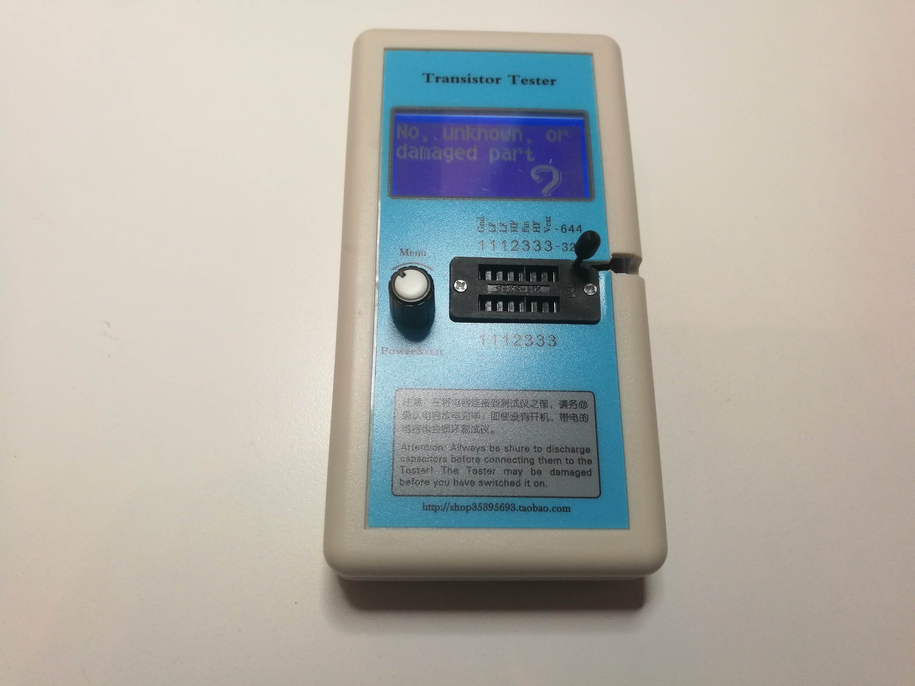
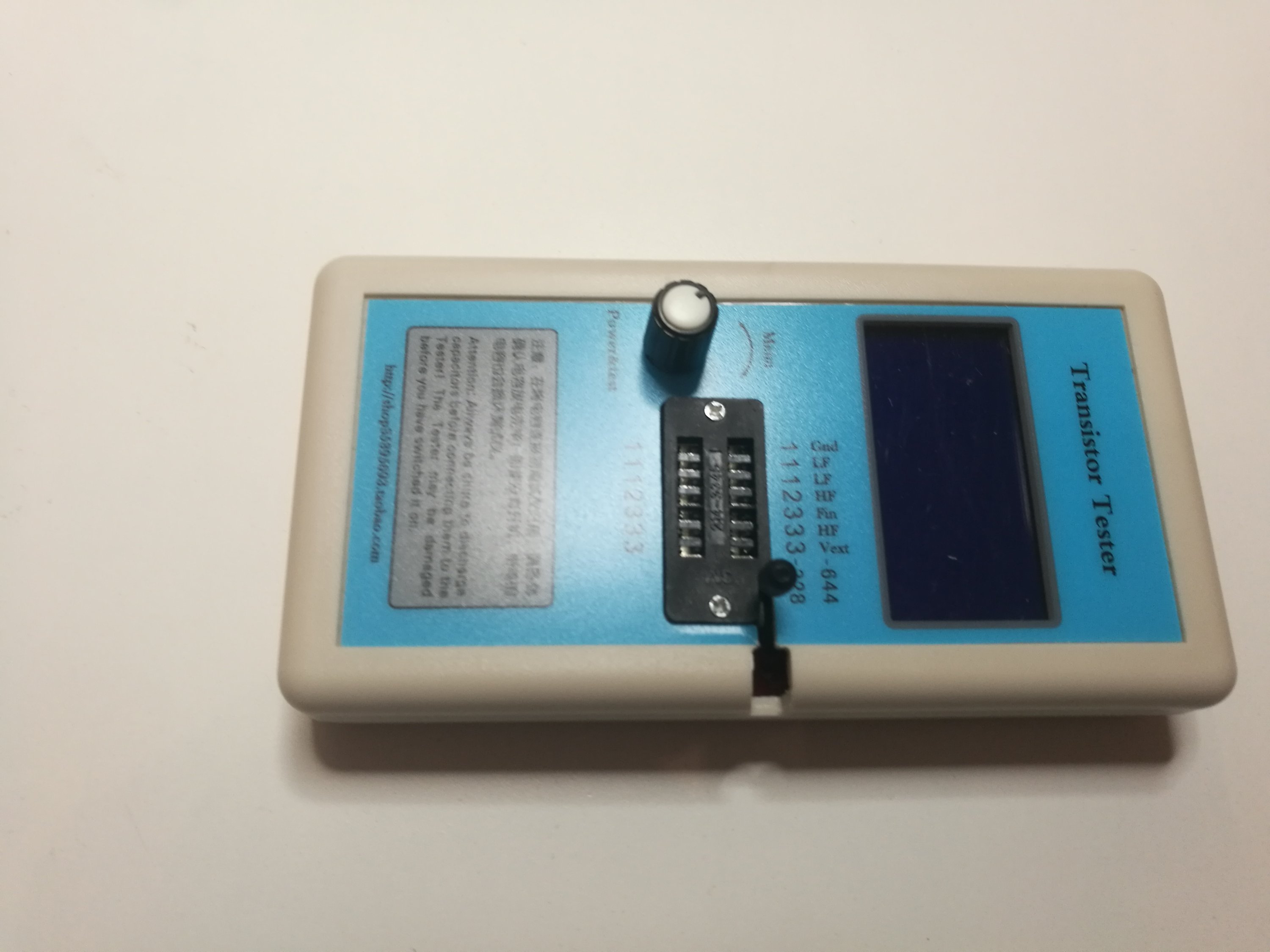
The end result was a decently looking test instrument ready to use. This is much better than just board without protection. I think this case was worth of the price (around 7 USD/EUR).
4 Comments
Tomi Engdahl says:
Review: Continuing the search for the ultimate LCR meter
https://www.edn.com/review-continuing-the-search-for-the-ultimate-lcr-meter/
Tomi Engdahl says:
https://www.edn.com/review-continuing-the-search-for-the-ultimate-lcr-meter/
Tomi Engdahl says:
A Low-Cost Operational Amplifier Tester to Find Faulty ICs
Circuit not working? This IC tester can help you idenify if your op amp is the problem.
https://www.hackster.io/news/a-low-cost-operational-amplifier-tester-to-find-faulty-ics-6dc61a6fe5a6
when it comes to an IC, it becomes very difficult to test the working of an integrated circuit. This project by lonesoulsurfer demonstrates the way of checking commonly used ICs like the LM358, LM386 and LM741 with his custom PCB.
As we all know, any operational amplifier IC has an inverting and non-inverting input, and this tester circuit uses the voltage comparator that is already present inside this IC. When there is a 50% duty cycle the output is always a square wave that results in flashing of the LED.
https://www.instructables.com/OP-Amp-IC-Tester/
Tomi Engdahl says:
https://www.mikrocontroller.net/articles/AVR_Transistortester#Introduction_(English)