An ideal power inverter will produce same kind of power that is available from mains outlet, which typically means sine waveform 60 Hz 11-120V AC or 50 Hz 220-240V AC. That kind of power source can power all mains powered devices as long as enough power is available. Where power inverter devices substitute for standard line power, a sine wave output is desirable because many electrical products are engineered to work best with a sine wave AC power source. The standard electric utility provides a sine wave, typically with minor imperfections but sometimes with significant distortion.
Producing sine-wave power is complicated and more expensive than square wave or modified sinewave power. A pure sine wave inverter is safe for use with a widest range of devices, but the hugh cost associated with pure sine wave inverters isn’t always worth it but sometimes this type of inverter is absolutely necessary.
Sine wave inverter is a power inverter device which produces a multiple step sinusoidal AC waveform is referred to as a sine wave inverter. Almost all consumer grade inverters that are sold as a “pure sine wave inverter” do not produce a smooth sine wave output at all, just a less choppy output than the square wave (two step) and modified sine wave (three step) inverters. However, this is not critical for most electronics as they deal with the output quite well.
Audio amplifier used to generate sine wave power
Making a pure sinewave inverter is (in theory) not especially difficult. All you need is a sinewave oscillator of the right frequency, a power amplifier to provide the current you need, and a transformer to increase the voltage to 230V or 120V RMS. Unfortunately, this is very inefficient and makes poor use of the battery’s capacity. Expect to get very high conversion losses so that almost half of the input power is lost in conversion process. Expecting better than 70% overall efficiency is generally unrealistic unless the sinewave is clipped to the extent that it resembles a squarewave.
One idea for laboratory use: function generator generates 50 or 60 Hz sinewave, that wired to hifi or PA amplifier that drives mains transformer low voltage winding. You can get some low power (up to tens of watts) at very pure sinewave at amplitude and frequency you want. The downside is expensive, low power and poor efficiency. A wien bridge oscillator can be used to generate sine wave. If you feed that sinewave signal to a powerful amplifier connected to a transformer, you can make an inverter. I have used sinewave fron function generator wired to audio amplifier wired to transformer to make AC at various frequencies.
For laboratory use you can make a low power sinewave inverter by taking a 50 Hz or 60 Hz signal source (function generator or other oscillator circuit that can give out sine waveform), suitable audio power amplifier and power transformer for stepping up the output voltage. If you amplify the signal with the amplifier to for example to 12V, and feed that to the transformer 12V coil, you can get low power sine wave mains power out from transformer primary. When using this method you need to keep in mind that the output power is limited by the power available from amplifier and that the load needs to be within amplifier safe operating range (typically expect to have 4 or 8 ohms speakers in them). Also in some audio applications 100V line voltage is used (either directly from amp or using step-up transformer). With this method you can’t get very high powers and efficiency is bad.
Most of the conversion power loss in this method happens at the audio power amplifier. With typical AB type HIFI audio amplifier, the amplifier is only 50% efficient. With different kind of amplifier you can get the system more efficient. It’s possible to get a properly designed Class-D amplifier to have an efficiency of between 80% and 90%, but there will also be transformer losses that must be considered. Modern switching audio amplifiers need no or small heatsinks even for 100s of Watts.
Sine wave with filtering
Can you convert a square wave to a sine wave in an inverter output? It is theoretically possible to filter square signal to sine wave, but that’s not generally practical approach, because the needed power components for the filter would become big and expensive.
Let’s pick one circuit example from this category. Quora mentions that L-C resonant filter have been earlier used on some square wave to sine wave conversion applications. Web page https://www.quora.com/How-do-I-convert-a-square-wave-to-a-sine-wave-in-an-inverter-output that you can use a set of harmonic traps like this:
Each series L-C set is tuned to be resonant at its specific harmonic. This means that the set appears as a near-short circuit to that harmonic frequency. Capacitor C1 is a “tank” capacitor chosen to be resonant with the overall equivalent inductance of the upstream components at the fundamental frequency..
This filter is quite large and heavy, and can only bring the total harmonic distortion in the output voltage waveform down to 10% at best. Thus quasi-square wave inverters have largely been replaced by other high-frequency modulation methods.
Sine wave with Pulse Width Modulation (PWM)
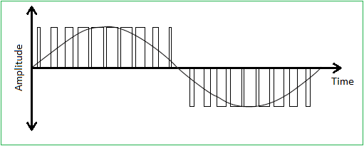
PWM is the technology of choice for maximum efficiency and a clean sinewave output. Many inverters use a PWM to create a waveform that can be low pass filtered to re-create the sine wave. The modulation frequency should be high enough to ensure no-one can hear it, which typically means at least 25kHz. Lower frequencies can be used, but the noise from the transformer or filter inductor may be intolerable and the filter components will be larger and more expensive.

The signal can also be generated with a special IC or a microprocessor. If microprocessor is used to generate the switching timing, the harmonic content and efficiency can be closely controlled.
When the control signal is generated, that can be used to drive power FETs that handle switching. Because the FETs are driven always either full on or full off a good efficiency is possible. For generating the mains voltage there are two main techniques: low voltage side switching and high voltage side switching. At low voltage side switching the FETs switch the typically 12V power to the step-up transformer low voltage side and the mains voltage is available on the transformer output. For any high power inverter, the transformer becomes a major part of the unit, in size, weight and cost.
The other method is to use a switch-mode step-up power supply to convert the voltage up, and then use high voltage FETs to generate the mains output from it. The output stage then works with the full peak voltage, either 325V or 170V DC, to suit 230V and 120V mains respectively. You can view the electronics inside one such inverter at my tear-down article at https://www.epanorama.net/blog/2017/05/20/sinewave-dc-to-ac-inverter-teardown/.
Elliott Sound Products article Inverter AC Power Supplies shows the theory and circuits related to AC power inverters from square wave to sine wave output designs.
Simple Sinewave Inverter Circuits page at https://makingcircuits.com/blog/simple-sinewave-inverter-circuit/ has many circuit examples.
Texas Instruments has published a 800VA Pure Sine Wave Inverter’s Reference Design at https://www.ti.com/lit/pdf/slaa602. This application note describes the design principles and the circuit operation of the 800VA pure Sine Wave Inverter.
Project examples
WARNING: Those circuits produce potentially lethal output voltages! Those circuits operate at quite high power, any mistakes on the circuits can lead to electrical shock and fire danger. I have not tested those circuits myself, so I can’t guarantee that they work at all. Use those only as generic reference to understand circuit operation, and do not try to build your own inverters based on them unless you understand all the dangers involved and can add the needed protection circuits that could be missing from the presented designs.
PWM Inverter Circuit diagram project page at https://theorycircuit.com/pwm-inverter-circuit/ describes a project that claims to be simple and powerful PWM inverter circuit. It promises to give up to 230V AC from 12V DC supply.
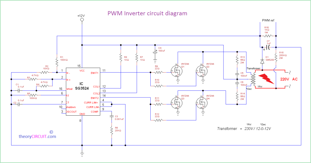
The circuit is diagram designed with IC SG3524 (Regulating Pulse Width Modulator) that drives power MOSFETs. The PWM switching pulse generator is the main part of this circuit, which is responsible to produce PWM pulse according to the sine wave reference. Output from Emit1 and Emit2 pins are directly fed into Switching device that is constructed by N channel MOSFET IRFZ44. The step up Output driver contains a transformer 230V primary to 12-0-12V secondary with 2 Amp current rating, which means power is limited only to around 24W only.
DIY Cheap 1000W Pure Sine Wave Inverter (12V to 110V/220V) project at https://www.instructables.com/DIY-Pure-Sine-Wave-Inverter/ is a detailed tutorial on building a HIGH POWER 12v to 220v pure sine wave inverter board from scratch. The project is based on the low cost EGS002 SPWM driver board module. The DIY inverter board is claimed it can handle up to more then 1kW, depending the transformer size that you are using.
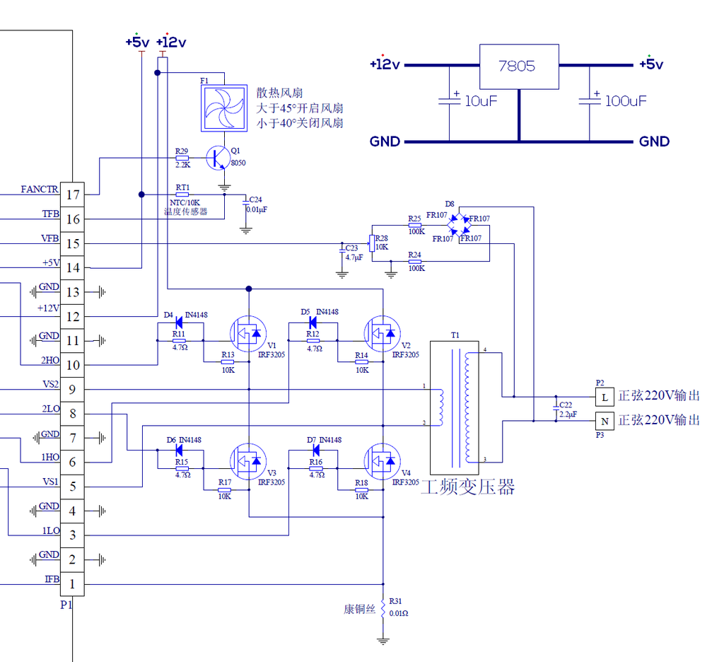
Here the EGS002 SPWM driver board module does all the magic generating the drive signals for the FETs that form a H-bridge driver that controls the power transformer primary. Here is a video of the project: DIY Cheap 1000W Sine Wave Inverter (12V-220V – EGS002)
The project Facebook posting describes the project like this:
- The surplus UPS inverter transformer is suspected to be a 500W based from forum discussions of its unknown part number.
- If connected to a larger transformer, the board should be able to accomodate +1kW.
- Standby power consumption ranges from 12W-17W depending on transformer used. Can still be improved.
- Uses an EGS002, a driver board that contains most of the logic and driver circuits. You can design and build different types of closed loop inverter structures with different max power output around the module.
- Ouput voltage regulation is good.
- Effeciency can be increased by building a single coil inductor version for high speed switching. (smaller by build size too!)
Project using ready control board
Simple Sinewave Inverter Circuits web page is a collection of simple sinewave inverter circuits, which can be customized for different needs. Those ideas may help you to achieve your objectives
Does it suck? Chinese DIY Pure Sine Wave Inverter || Sinusoidal PWM (SPWM) Tutorial video tells the basics about SPWM and show you how we can use it to create a pure sine wave. It will have a look at the EGS002 which is a cheap SPWM driver board from China that can be used to create a DIY pure sine wave inverter.
Control board links:
12V 300W 50Hz Inverter Driver Board Low Frequency Transformer Converter Module Flat Wave Power
https://www.banggood.com/12V-300W-50Hz-Inverter-Driver-Board-Low-Frequency-Transformer-Converter-Module-Flat-Wave-Power-p-1572209.html?rmmds=detail-left-hotproducts__4&cur_warehouse=CN
DC-AC 5V Pure Sine Wave Inverter SPWM Driver Board EGS002 EG8010 + IR2110 Driver Module 12Mhz Crystal Oscillator CMOS RS232 Over-Voltage Under-Voltage Over-Current Over-Heating Protection
https://www.banggood.com/DC-AC-5V-Pure-Sine-Wave-Inverter-SPWM-Driver-Board-EGS002-EG8010-IR2110-Driver-Module-CMOS-RS232-p-1197219.html?rmmds=detail-left-hotproducts__5&cur_warehouse=CN
Microprocessor based sine wave inverters
Sine Wave Inverter Using Arduino and This Sine Wave Inverter Using Arduino 50Hz and Sine Wave Inverter Using Arduino Update
videos describes a Sine Wave Inverter with variable frequency controlled Using Arduino.
28 Comments
Tomi Engdahl says:
Amplifiers designed for 100V line applications can be used to generate around 110V AC
https://www.electronics-tutorials.ws/transformer/audio-transformer.html
Tomi Engdahl says:
Convert Audio Amplifier into Pure Sinewave Inverter
https://www.homemade-circuits.com/making-sine-wave-inverter-from-audio/
Tomi Engdahl says:
https://www.instructables.com/DIY-Pure-Sine-Wave-Inverter/
Tomi Engdahl says:
DIY Cheap 1000W Sine Wave Inverter (12V-220V – EGS002)
https://www.youtube.com/watch?app=desktop&feature=youtu.be&v=I8c5DLJgS3o
Tomi Engdahl says:
https://microcontrollerslab.com/single-phase-pure-sine-wave-inverter/
https://circuitdigest.com/microcontroller-projects/arduino-waveform-generator
https://duino4projects.com/sinewave-inverter-circuit-using-arduino/
Tomi Engdahl says:
What is the difference between modified, pure sine wave inverters?
https://theinverterstore.com/faq-items/what-is-the-difference-between-modified-pure-sine-wave-inverters/
There are 3 major types of inverters – pure sine wave (or “true” sine wave), modified sine wave (actually a modified square wave), and square wave.
Pure Sine Wave A pure sine wave is what you get from your local utility company and from some pure sine generators (most generators are not pure sine).
major advantage of a pure sine wave inverter is that all of the equipment which is sold on the market is designed for a pure sine wave. This guarantees that the equipment will work to its full specifications.
Some appliances, such as motors and microwave ovens will only produce full output with pure sine wave power.
A few appliances, such as bread makers, light dimmers, and some battery chargers require a pure sine wave to work at all.
audio equipment, satellite systems, and video equipment, will run properly using pure sine wave inverters.
these are the most expensive of the inverter designs and outperform all other types of inverters, regardless of use.
Analog Pure Sine Wave The sine wave produced by an analog pure sine wave inverter, is very similar to that of the digital pure sine wave inverter. The key difference is that the analog switching causes noise or static on the ac wave.
Modified Sine Wave (quasi-sine) A modified sine wave inverter actually has a waveform more like a square wave, but with an extra step. A modified sine wave inverter will work fine with most equipment, although the efficiency or power of the equipment will be reduced with some.
Motors, such as refrigerator motor, pumps, fans etc will use more power from the inverter due to lower efficiency. Most motors will use about 20% more power. This is because a fair percentage of a modified sine wave is higher frequencies – that is, not 60 Hz – so the motors cannot use it.
Some fluorescent lights will not operate quite as bright, and some may buzz or make annoying humming noises.
Square Wave Very few but the very cheapest inverters any more are square wave. A square wave inverter will run simple things like tools with universal motors with no problem – but not much else. These are seldom seen any more except in the very cheap or very old ones.
Tomi Engdahl says:
The problems with non sinewave inverters are that some chargers might not work with them (no output) and in some cases more noise can be coupled to charger output causing problems like bas touch screen operation when device plugged to charger connected to inverter.
Tomi Engdahl says:
DIY Cheap 1000W Sine Wave Inverter (12V-220V – EGS002)
https://www.youtube.com/watch?v=I8c5DLJgS3o
A detailed tutorial on building a HIGH POWER 12v to 220v pure sine wave inverter board from scratch. The project is based on the low cost EGS002 SPWM driver board module. The DIY inverter board can handle more then 1kW, depending the transformer size that you are using. (mine is 500VA, only yielded 400W at the moment)
Tomi Engdahl says:
Does it suck? Chinese DIY Pure Sine Wave Inverter || Sinusoidal PWM (SPWM) Tutorial
https://www.youtube.com/watch?v=Dn2PFebi2ww
Tomi Engdahl says:
Convert Square-Wave Inverter into Sine-Wave Inverter
https://www.youtube.com/watch?v=4OFrFbmi5g0
I just bought a square wave inverter from a second hand store, Today’s project, I will convert this square wave inverter into a sine wave inverter. Using module EGS002.
Tomi Engdahl says:
Tekoälyllä eroon tehohäviöistä
https://etn.fi/index.php/13-news/12035-tekoalylla-eroon-tehohavioista
https://www.pre-switch.com/technology
Tomi Engdahl says:
Sine Wave inverter using PIC16F76
https://labprojectsbd.com/2020/04/18/sine-wave-inverter-using-pic16f76/
Tomi Engdahl says:
TSP #191 – Teardown, Repair & Experiments with a GW-Instek APS-1102 Programmable AC/DC Power Source
https://www.youtube.com/watch?v=TYFt-vlXcew
In this episode Shahriar takes a look at a GW-Instek programmable AC/DC source with 1kVA, 200V capability. The instrument is ideal for power applications since it offers customized waveforms as well as AC+DC output. The unit shows COMMUNICATION ERROR 2 when powered which indicates an internal module-to-module fault. An X-Ray of the main processor board shows the various power supply planes and isolated sub-components communicating through optocouplers. The power supply design is reverse engineered and the fault is traced to a set of bad operational amplifiers. All broken components are replaced which restores the unit’s functionality. The instrument is then tested to show some of its capabilities.
Tomi Engdahl says:
DIY 1kW Sine Wave Inverter (12V-220V – EGS002)
https://www.youtube.com/watch?v=I8c5DLJgS3o
A detailed tutorial on building a HIGH POWER 12v to 220v pure sine wave inverter board from scratch. The project is based on the low cost EGS002 SPWM driver board module. The DIY inverter board can handle more then 1kW, depending the transformer size that you are using. (mine is 500VA, only yielded 400W at the moment)
https://www.instructables.com/DIY-Pure-Sine-Wave-Inverter/
Tomi Engdahl says:
Powerful 5000W 12V 48V Sine INVERTER
https://www.youtube.com/watch?v=59EDpoOdj0g
Hello, Today I will share with you a new project. It is 5KW inverter using 24 mosfet. It can work at 12V to 48V. Power at 12v is 1500W, Maximum power at 48V is 5000W, Of course that’s the capacity of the board, You will need a large enough transformer. Need a 20Kg transformer for 5000W / 48V. If using 12V, I recommend mosfet IRF1404, 48V is IRFB4110.
Tomi Engdahl says:
Amp Powers an Amp and Does Hot AC give more Watts? (Public)
https://www.youtube.com/watch?v=3AYJBUaT74Q
In this test I am using a Powersoft X4 power amp to create “wall voltage” and power up a Crest 4801 power amp.
Tomi Engdahl says:
Siniaalto: Kaikista paras vaihtoehto, tuottaa samanlaista sähköä kuin saadaan kotipistorasiasta. Modifioitu siniaalto: Lähes samanlaatuinen sähkö kuin kotona, lähes kaikki laitteet toimivat ongelmitta. Kanttiaalto: Halvin vaihtoehto. Välttämättä kaikki laitteet eivät toimi. Lisäksi lyhentää käämillisten laitteiden elinikää ravistamalla lakkaukset rikki.
Tomi Engdahl says:
Sellainen invertteri, joka ei tee “oikeaa” siniaaltoa on itse asiassa yleensä paras kaikkeen käyttöön.
Siinä on paras hyötysuhde ja pienin tyhjäkäyntivirta.
Ja mihin sitä “oikeaa” siniaaltoa sitten tarvitaan?
Aika harvaan laitteeseen, jos oikeasti mihinkään.
Lähes kaikki laitteet toimivat joko muuntajalla tai hakkuriteholähteellä.
No hakkuriteholähteessä se “siniaalto” tasasuunnataan ja ladataan konkkaan, josta laitteen oma hakkuri tekee sitten tarvitsemasnsa jännitteet.
Muuntaja taas toimii alipäästösuotimena, joka aika kivasti tasottaa “moidified sinus” inverttereiden kanttiaallot.
Sähkömoottorit jne taas toimii melko rumallakin kanttiaallolla ihan moitteetta.
Mikroaaltouuni ei tykkää epäpuhtaasta invertterin sähköstä, ehkä hajakenttämuuntajansa takia.
Lähes kaikki muut kuluttajalaitteet on tähän mennesä mun labrauksissa toimineet ihan tyydyttävästi niill’ä halisinuilla, jotka ei tee oikeaa siniaaltoa.
-M-
Tomi Engdahl says:
how to make simple inverter 4500W , sine wave , 8 mosfet , IRFz 44n ,jlcpcb
https://www.youtube.com/watch?v=QS-aeVLagxA
Tomi Engdahl says:
Audio amplifier generates AC
https://youtu.be/3AYJBUaT74Q
Tomi Engdahl says:
Pure sine wave inverter using PIC16F76
https://labprojectsbd.com/2020/04/18/sine-wave-inverter-using-pic16f76/
Tomi Engdahl says:
So Excited!!! Full SINE Inverter PCB at 230V and 50Hz
https://www.youtube.com/watch?v=xPGtNmJEmCs
Finally, I make a homemade Full sinusoidal Inverter suing the EGS002 driver. It could easily deliver 500W or more at 220V 230V and 50Hz. Get the PCB files and make your own and also learn how it works.
Tomi Engdahl says:
https://www.watelectronics.com/sine-pulse-width-modulation-spwm-working/
Rodolfo Bennett says:
Sine wave inverter technology is crucial for converting direct current (DC) into alternating current (AC) with a smooth sinusoidal waveform. It ensures compatibility and efficiency when powering sensitive electronics like laptops, refrigerators, and medical equipment. To learn more about the web developer’s salary trends, check out this insightful article: https://mobilunity.ch/blog/webentwickler-gehalt/. Stay informed and make informed decisions in the dynamic field of web development.
Tomi Engdahl says:
https://www.homemade-circuits.com/arduino-pure-sine-wave-inverter-circuit/
Tomi Engdahl says:
PAPER • OPEN ACCESS
Design of front-end push-pull sine wave inver
https://iopscience.iop.org/article/10.1088/1755-1315/295/3/032094/pdf
Tomi Engdahl says:
The design and implementation of a microcontroller-based single phase on- line uninterrupted power supply with power factor correction
https://www.researchgate.net/publication/224091449_The_design_and_implementation_of_a_microcontroller-based_single_phase_on-_line_uninterrupted_power_supply_with_power_factor_correction
Tomi Engdahl says:
Topic: Disadvantages of Using half-wave instead of full-wave in Pure Sinewave Inverter?
https://www.eevblog.com/forum/projects/disadvantages-of-using-push-pull-in-pure-sine-wave-inverter/
Every pure sinewave inverter, I knew or heard of (12Vdc or 24Vdc to 220Vac), that uses laminated iron transformer (input: 1 coil, output: 1 coil) drives its transformer with a 4-MOSFET bridge.
Lately, I am designing a pure sinewave inverter but by using 2-MOSFET push-pull driver (lower side only) with a half-wave transformer (input: 2 coils, output: 1 coi).
I used to believe that simplifying a board likely creates some disadvantages.
So, I hope some experienced engineers here could help me know in advance certain expected disadvantages in using the push-pull configuration, in this case, instead of a bridge.
Thank you.
Kerim
What do you mean by 2 mosfet push pull ?
If you mean 2 N MOSFETS in half wave drive, yes, that saves 2 MOSFETS but
* you now need 2 clamp circuits
* worse, is the current flows in half the transformer copper at a time.
It’s the same reason half wave rectifiers ‘waste’ transformer resource, and bridge rectifiers are preferred.
Good remark,
If I understood you well, the price is more copper at low-voltage side in order to get the same resistance of the 1 coil transformer (driven by a bridge).
But let us also recall that the resistance added by a bridge is 2*Ron instead of 1*Ron in case of half wave drive.
Quote from: coromonadalix on March 18, 2024, 01:59:34 am
using any mcu for generating a sinal will not be pure as you need, it will be called pseudo sinusoidal, you’ll need good filtering, if you want to acheive a somewhat good sinus wave out of it
You are right in case the code is not well written. For instance, I had to write my codes, since early 80′s, in assembly language only because I couldn’t get, for free or else, high language compilers as of C for example.
I managed to output the SPWM signals at pins OC1A and OC1B of ATmega8 (using fast PWM of timer 1). The rate is 15,625 Hz. The number of samples per cycle (50 Hz) is 312.
The amazing thing is that the small leakage inductance of the iron power transformer does the filtering with a relatively small high voltage capacitor (around 1 uF). I am not sure how good (speaking THD) the sinewave, I got, is. But it looks on the scope screen it looks a sine wave without ripple.
Naturally, to maintain 220V at the output, the MCU reads the output voltage in every cycle (50 Hz) to adjust the gain of the PWM for the next cycle. This voltage regulation allows a soft start at boot (from 0V to 220V, in 800ms). The MCU has other functions related to safety in case of faults.
Quote from: coromonadalix on March 18, 2024, 01:59:34 am
you could have some equipment compatibility problems
IE i have some laptop chargers who wont refuses to start even with pseudo signal inverters, with pure sinewave they start etc …. some tv’s dont work too (they use ac-dc adapters)
In the last 12 years, I produced and sold about 5 thousand ‘adaptive square wave’ inverters (regulated by varying the duty cycle). Lately, it became clear that every device (made for 50Hz sinewave) whose power supply uses a series capacitor to limit the internal supply current, is damaged, sooner or later, by a square wave inverter. Summer is at the door and electric fans will be used soon. Most of these fans are controlled by electronic boards supplied internally by a series capacitor (no more by a small transformer). So, I decided to also produce low-cost sinewave inverters, at least for these fans.
I admit that with the limited available components around me I can’t do miracles by making such inverters also with high efficiency. Losses in the iron transformer whose available laminated core is also of the lowest possible grade! (Bs=1.05 Tesla, Br=0.7 Tesla and Hc=100 A/m) is much higher than of ferrite’s.
Re: Disadvantages of Using half-wave instead of full-wave in Pure Sinewave Inverter?
« Reply #22 on: March 19, 2024, 03:43:02 am »
Quote from: Zero999 on March 18, 2024, 03:48:17 pm
Why not put the filter before the transformer?
Only half of the power in the PWM waveform is delivered to the load. Half of it is blocked by the filter. There’s no point in the transformer passing the unnecessary harmonics and generating the associated losses. It’s better to filter them out first.
For instance, Zero999 (reply #4) reminded us of the most efficient topology to build a pure sinewave:
“The ones I’ve seen use an isolated DC:DC converter to a get DC of the peak voltage of the mains, followed by a MOSFET H-bridge and filter.”
I guess you know that in this case the DC:DC converter and the output filter have to be made on ferrite cores which I can’t get in quantities.
Should I forget producing pure sine wave inverters just because the new world allows me to use the lowest grade of laminated iron only (besides many other limitations)? On the other side, almost all engineers around the world (I hope) can get, in one way or another, whatever they may need in their designs.
I even chose the half wave drive instead of the full wave one to reduce even more the cost and labor.
Now, returning to your suggestion, how the filter could be done without using a ferrite choke? I hope you get the idea.
Re: Disadvantages of Using half-wave instead of full-wave in Pure Sinewave Inverter?
« Reply #24 on: March 19, 2024, 04:36:20 am »
Quote from: Kim Christensen on March 18, 2024, 03:39:27 pm
Quote from: KerimF on March 18, 2024, 09:44:10 am
I am somehow surprised that most members here didn’t hear yet how pure sine wave inverters can also use a laminated iron power transformer. I heard of such inverters in many other EE forums, since more than a decade ago.
Because there are much better ways of doing it. (I know you can’t do it the standard way due to lack of parts). You’re going to have large eddy current losses in the transformer which will cause it to heat up. This will reduce efficiency and require extra cooling of the transformer and/or require it’s power output to be derated. After Googling about others who have done the same as you’re proposing, they run into exactly this problem. The transformer overheats and requires extra cooling.
I agree with all you said.
About the extra dissipation of the transformer, this may be a problem if the inverter is loaded at its maximum power for a long time. Actually, it is not the case for most local consumers, if not all, who have to preserve their battery charge as long as possible.
Soon after year 2011, we lost the mains network completely. With time, mains electricity has been restored gradually. And now (after 12 years), we get the mains voltage (220V, 50Hz) 6 hours per day at best.