A resistor is a resistor, a coil is a plain ol’ inductance, and a capacitor is a capacitor – or so you thought. Alas, life isn’t quite so trivial…
There are non-ideal properties of real components. Capacitors have non-idealities that you should know about when designing electronics circuits. If you are building high frequency circuits or hifi audio circuits, you need to be very careful what capacitor type to use and what not to use. Here is an overview of discussion on capacitors distortion in audio applications.
Capacitor Distortion Mechanisms
http://stephan.win31.de/capdist.htm
article says:
Real resistors, capacitors and inductances can be non-ideal in various ways.
First there are the linear non-idealities that can be described by linear “parasitic elements”, the number of which varies with the degree of detail required. Usually the higher the frequencies involved, the more complex the model becomes.
Capacitors: Linear considerations
When choosing capacitors for a given application, one normally looks at their linear properties first – it would, for example, be of little value to use an ordinary electrolytic cap to get rid of supply voltage ripple in the MHz range, since due to its high series inductance the poor thing would not only not work very well, but may also heat up and dry out prematurely. If nonetheless high capacitance requirements and high frequencies come together, a proven trick has been using multiple capacitors in parallel, for example two or even three different ones with descending capacities (typically factors of a little more than 1:100, depending on the combined impedance characteristics – one does not want resonance peaks), where generally the smaller caps are closer to the device that might be sapping power with such a high frequency (up to final supply bypass caps being only millimeters away from supply pins in things like DACs). Other important parameters include things like temperature stability and losses (ESR, dissipation factor etc.).
Nonlinear effects in capacitors
In some applications, however, nonlinear effects may become disturbing. Effects and underlying mechanisms that may appear are:
Polarity. Of course a polar capacitor (any kind of electrolytic) is inherently nonlinear. These are typically modelled as a nonpolar capacitor with an imperfect diode in parallel. Therefore these make for a pretty decent short when significantly reverse biased – if this happens, the results may be phunni indeed, up to outright explosion (tantalums are pretty nasty in that regard, it’s the magnesium in their electrodes that tends to ignite).
Change of relative permittivity (relative dielectric constant, εr or K) with electric field strength – εr = εr(E). This reflects linearly in capacitance, so effectively C = C(U). It is obvious that given the same external voltage, thinner dielectric layers found in capacitors with lower voltage ratings will worsen the effect (same voltage drop in less distance means higher fieldstrength).
Piezoelectric effect. If dielectric layers contract or expand with applied voltage (an effect used for piezo buzzers), this will directly affect capacitance – again, C = C(U). This is mainly found in high-K ceramic capacitors, as these contain barium titanate which is very piezoelectric – for the very high capacitance types, you may find that they’ve lost 80% of their capacitance at rated voltage (ouch). This effect is actually used to build ceramic resonators which are employed as IF filters and discriminators.
Dielectric absorption (DA) or “capacitor soakage”. Take a charged capacitor, then quickly dischange it, then wait for a while – and the voltage measured at its terminals will not be zero. That’s DA in a nutshell. This kind of hysteresis or “memory” may generate funny distortion as well as keep analog computing circuitry from working correctly. As you may remember, hysteresis is typical for ferromagnetic materials and may therefore be an issue when working with things like output transformers. DA can be described with an infinite number of parallel R-C networks, which one might consider a linear model, but I guess the infinite number is the problem.
Leakage current varying with applied voltage – mainly an issue of electrolytics. Significant leakage current in itself seems to be problematic in some applications, e.g. coupling capacitors. If it happens to flow through the volume pot in an audio amplifier, you may get a lot of scratching when adjusting the volume even if the pot itself is fine.
Degradation of leakage current and other parameters if left without bias voltage (or with a very low one, compared to their maximum rating) for a long time – an effect unique to Al electrolytics.
Degradation of ESR and capacity due to the capacitor physically drying out – another effect unique to Al electrolytics.
The worst offenders are easily named – it’s high-K ceramics, tantalum and electrolytic capacitors, all of them types using dielectrics with high relative permittivity. The best performers include caps using polystyrene, PTFE (a.k.a. Teflon®), air/vacuum (of course) and also NP0 ceramics, where εr is much lower. (That’s relatively speaking – the dielectric in NP0 ceramics in fact has a permittivity higher than that in electrolytics, but compared to other ceramics this still is very low.)
The change in capacitance with applied voltage is known as the capacitor’s voltage coefficient, and it can be the dominant source of distortion in the low-frequency spectrum where capacitor impedance is relatively high. Furthermore, as the signal amplitude increases, greater distortion occurs.
Signal distortion from high-K ceramic capacitors
https://www.edn.com/signal-distortion-from-high-k-ceramic-capacitors
article says:
Multilayer ceramic capacitors (MLCCs) are used extensively in modern electronics because they offer high volumetric efficiencies and low equivalent series resistances at attractive prices. These advantages make MLCCs nearly ideal for a wide range of applications, including output capacitors for power supplies and local decoupling capacitors for integrated circuits. The various types of MLCCs are delineated primarily by their temperature coefficient
high-K MLCCs exhibit a substantial voltage coefficient, meaning their capacitance varies depending on the applied voltage. In AC applications this phenomenon manifests itself as waveform distortion and can compromise the overall system performance. When printed circuit board (PCB) area and cost are major design constraints, board and system level designers may be tempted to use high-K MLCCs in circuits where they can introduce significant distortion into the signal path.
Active filter circuits, anti-aliasing filters for data converters, and feedback capacitors in amplifiers are examples of circuits where the use of a high-K MLCC may introduce distortion.
Capacitor Characteristics
https://sound-au.com/articles/capacitors.htm
article says:
The findings are useful for determining the usefulness of various caps in filter circuits (especially passive crossover networks) though, and he quickly disposes of a number of persistent myths, including (but not limited to) the following:
All ceramic capacitors introduce distortion
Dielectric absorption compresses dynamic range and ‘smears’ audio
Polyester dielectrics are lossy and inefficient
Capacitors look inductive at audio frequencies
A capacitor’s ESR is a fixed quantity
1.4.1 – Ceramic Capacitor Acoustic Noise
There’s quite a bit of information available on this topic, but fortunately (at least for audio applications) it isn’t usually a problem. High-k ceramic caps will almost always have a piezoelectric effect, meaning that they will vibrate when subjected to an alternating current and will generate a voltage if vibrated. Of particular concern are high-value ceramic caps (10µF or more), as they are physically larger. The capacitor itself will normally be silent, but the PCB may act as a ‘sounding board’, amplifying the noise to the point where it can become audible [ 14 ]. As noted in the reference, there are solutions.
No purely analogue solution (using opamps or discrete components) will have a problem, especially if built using through-hole parts. I never specify high capacitance multilayer caps in any design published, with the largest normally suggested being 100nF. Since these are used in parallel with opamp supply pins, they have an electrically quiet environment to start with, and as they are through-hole the opportunity for noise is negligible.
Where this issue becomes problematical is with SMD caps, subjected to a noisy supply, and especially in small ‘personal’ devices where size and cost preclude the use of ‘acoustically silent’ capacitors. Many of these may also utilise thinner PCBs than more traditional circuits, allowing the PCB to flex more easily. In general, this isn’t something you’ll need to worry about with any of the ESP projects, but it is something you need to be aware of.
The series resonance of an electrolytic (or any other capacitor) has to be considered in conjunction with the circuit impedance. In real life devices, it is actually quite a broad null, often extending over several decades of frequency. This is readily apparent from looking at manufacturers’ data, or by measurement. Measurement is actually quite difficult, since a significant current must be applied to be able to see the results.

Capacitor Distortion
https://www.angelfire.com/ab3/mjramp/capdist.html
article says:
Applying a sine wave voltage and measuring the distortion in the current through a capacitor can provide figures for harmonic distortion. At zero dc bias non-polarised types with symmetrical construction should have mostly third harmonic, expected from their symmetry, and higher order harmonics are generally found to be much smaller. Adding a dc bias increases the 2nd harmonic, as expected for any device with a primarily cubic non-linearity. Some capacitor types, e.g. high-k ceramics, are found to have unusually high levels of distortion and should be avoided in some audio applications. Most other types have very low distortion levels compared to other parts of the audio chain. Even electrolytics can have low distortion provided we take care to avoid reverse bias and keep the signal voltage across the capacitor small, which can be ensured by using a sufficiently large value, and keeping the current low, which is easy in some applications, but not in the case of a speaker coupling capacitor. D.Self found that a ‘standard’ 6800uF driving 40watts into 8ohms added no more than 0.0025% distortion down to 20Hz.
Why some ceramic Cs sometimes should NOT be used. p
https://www.pa0nhc.nl/CeramicCs/The_(BAD)_properties_of_ceramic_Cs.htm
article says:
FILM capacitors are far more stable than most ceramic capacitors.
Only NP0 (N P zero) or C0G (C zero G) type ceramic capacitors can be used in any application. They are stable.
The material types X7R, Z5U and Y5V of ceramic capacitors allow for much larger capacitance values in much smaller packages.
But they have big disadvantages.With voltages applied :
With varying DC voltages, the capacitance of a Z5U type capacitor can change up to -50% (!)
With varying AC voltages, the capacitance of a Z5U type capacitor can change up to +20% (!)On X7R and Z5U type ceramic capacitors, keep applied voltages below 10Vdc and 500mVrms.
X7R, Z5U and Y5V types are mainly suitable as decoupling capacitors in uncritical situations (with NO ACvoltages applied).
Practical Test & Measurement – Stop Worrying About Coupling Capacitors!
https://audioxpress.com/article/practical-test-measurement-stop-worrying-about-coupling-capacitors
Ethan Winer says he often sees arguments in hi-fi forums and Facebook audio groups about the importance of high-quality capacitors in the signal path. It’s true that capacitor quality varies wildly among the various types, and the main problem with poor quality capacitors is they can add distortion to audio passing through them. But for inter-stage coupling capacitors, this may not be as big a problem as many people think.
The main contributor to capacitor distortion is its voltage coefficient. This is a measure of how much the capacitance changes as the applied voltage varies. Ideally, a capacitor should have the same amount of capacitance no matter how much voltage is present across its terminals.
Another contributor to capacitor distortion is its dielectric absorption, which is a “memory” effect. After discharging a capacitor fully, some DC voltage reappears soon after because part of the charge was stored within the capacitor’s dielectric — the technical term for the insulating material between the metal plates.
Capacitor distortion greatly varies from very low with Mylar, polystyrene, and mica types to unacceptably high with some electrolytics, and even higher for ceramic types.
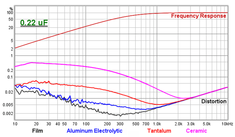
Coupled with a high-quality sound card (e.g., the Focusrite Scarlett 8i6), REW can be used to measure the distortion of passive components (e.g., capacitors and transformers) and even active devices such as equalizers and preamps.
Figure 3: Distortion with a 0.22 μF capacitor.
Links to more information:
https://www.google.com/url?sa=t&source=web&rct=j&opi=89978449&url=https://www.ti.com/lit/pdf/slyt796&ved=2ahUKEwipgpGsic-FAxWpBxAIHf0ACfkQFnoECA4QAw&usg=AOvVaw3XmiJwcAxbczzAaxCJ2afI
https://sound-au.com/articles/capacitors.htm
https://www.audiosciencereview.com/forum/index.php?threads/capacitor-distortion.40917/
https://www.edn.com/signal-distortion-from-high-k-ceramic-capacitors/
https://www.pa0nhc.nl/CeramicCs/The_(BAD)_properties_of_ceramic_Cs.htm
https://www.vintage-radio.net/forum/showthread.php?p=991100
https://www.edn.com/ceramic-capacitors-how-far-can-you-trust-them/
https://www.kemet.com/en/us/technical-resources/heres-what-makes-mlcc-dielectrics-different.html
https://audioxpress.com/article/practical-test-measurement-stop-worrying-about-coupling-capacitors
14 Comments
dino game says:
I wanna know more about this because this is really informative!
Tomi Engdahl says:
Tap on it. The socket itself is a mic now. Ceramic caps are a really bad choice for audio path. Apart from being microphonic they also change capacitance with applied voltage which means added distortion with large signals and applied DC bias can change the cutoff frequency of the filter it forms with the resistance of whatever it’s plugged into. NPO caps are generally stable but don’t usually come in value large enough for audio use
Tomi Engdahl says:
Mr Carlson’s Lab on YouTube has a video on how the outer casing of most nonpolar capacitors had an optimum installation arrangement to shield EMI. He also shares a circuit you can build to test for that.
https://youtu.be/BnR_DLd1PDI
Tomi Engdahl says:
Let’s see a photo of the more compact brand. The bigger one’s are non-polar poly——. The smaller ones are probably electrolytic, which explains the smaller physical size. Distortion is likely higher with the electrolytic, especially if it’s not biased.
Tomi Engdahl says:
Let’s see a photo of the more compact brand. The bigger one’s are non-polar poly——. The smaller ones are probably electrolytic, which explains the smaller physical size. Distortion is likely higher with the electrolytic, especially if it’s not biased.
nowadays there are also some small size ceramic capacitors that are not very suitable for audio applications
Tomi Engdahl says:
Capacitors electrical properties are more complex than most of the people think, specially in the low frequency (audio) analogue domain
Tomi Engdahl says:
Capacitors come in various types, including low ESR (Equivalent Series Resistance), high ESR, polar, and non-polar, because they serve different applications and electrical requirements. Let’s break this down:
1. ESR (Equivalent Series Resistance):
ESR represents the resistive component within a capacitor, affecting its efficiency and behavior in circuits.
Low ESR Capacitors:
• Purpose:
• Designed for high-frequency and high-current applications.
• Minimize power losses and heat generation.
• Suitable for switching power supplies, voltage regulators, and high-frequency filtering.
• Common Types: Aluminum electrolytic, tantalum, and ceramic capacitors.
• Advantages:
• Low heat dissipation during high-current flow.
• Better performance in fast signal filtering and transient response.
• Higher efficiency in energy storage/discharge cycles.
High ESR Capacitors:
• Purpose:
• Typically used in less critical applications where power dissipation and high-frequency performance are not a concern.
• Found in applications with low-frequency filtering or simple bypassing.
• Advantages:
• Lower cost.
• Stable behavior for low-speed, low-current circuits.
• Example: Older or cheaper electrolytic capacitors in non-demanding circuits.
2. Polar vs. Non-Polar Capacitors:
Polar Capacitors:
• Characteristics:
• Have a positive and negative terminal (polarity-sensitive).
• Can only be connected one way in the circuit.
• Includes electrolytic and tantalum capacitors.
• Purpose:
• Provide high capacitance values for energy storage or filtering in DC circuits.
• Used in power supplies, decoupling, and coupling applications.
• Limitation:
• Cannot be used in AC circuits directly because reversing polarity damages them.
Non-Polar Capacitors:
• Characteristics:
• No polarity; can be connected either way.
• Includes ceramic, film, and mica capacitors.
• Purpose:
• Suitable for AC and DC applications.
• Used in coupling, decoupling, oscillators, and timing circuits.
• Advantages:
• High stability and reliability in AC circuits.
• Less prone to failure from polarity issues.
Why Do These Types Exist?
1. Application-Specific Requirements: Different circuits and devices demand specific characteristics like low resistance, high capacitance, or compatibility with AC/DC.
2. Cost vs. Performance Trade-Off: Low ESR capacitors are typically more expensive but necessary for high-performance circuits. High ESR capacitors are cost-effective for simpler applications.
3. Design Constraints: Some designs require compact capacitors (tantalum), while others need stability and long lifespan (ceramic/film).
4. Frequency and Voltage Considerations: Low ESR capacitors handle high-frequency better, while high ESR capacitors suffice for low-frequency applications.
Practical Uses:
• Low ESR Polar: Used in high-performance DC power supplies, GPU/CPU VRMs, and switching regulators.
• High ESR Polar: Found in simple rectifiers or low-cost DC filtering.
• Non-Polar: Used in AC coupling, audio filters, and oscillators where polarity reversals occur.
Each type balances electrical properties with cost and intended use, ensuring optimal performance across different technologies.
Tomi Engdahl says:
https://hackaday.com/2025/01/27/film-capacitors-can-go-in-the-wrong-way-round-who-knew/
Tomi Engdahl says:
No it’s not polarised. The dots indicate the end of the capacitor that is connected to the foil that is on the outside of the capacitor. These capacitors are made by taking a foil of aluminium with a seperater between the foils. The whole thing is then rolled up to form the capacitor. Back in the day most low value capacitors had a dot or line painted one end. That mark indicated the outside foil. In some applications it was good practice to have the outside foil at the earth or 0V end of the circuit.
Tomi Engdahl says:
It has been known for a long time to not use certain ceramics in signal paths where low distortion in audio is critical. High dielectric types have a strong bias voltage dependance. https://www.eevblog.com/forum/projects/ceramic-capacitor-behavior/
Tomi Engdahl says:
https://www.eevblog.com/forum/projects/ceramic-capacitor-behavior/
Tomi Engdahl says:
Polystyrene > Polypropylene > Polyester > Electrolytic and Ceramic. This is a general rule. There someone who tested the linearity many years ago. The Poly (plastic) caps are all very close.
Tomi Engdahl says:
Bipolar’s have lower ripple current and hugher ESR compared to polarized, so they are not optimal for power supplies. At signal path the bipolars are superior, BUT – if the amp is designed with particular electrolytic in mind, it could sound different if recapped with caps with totally different make/chemistry. If its a vintage amp, I’d find replacement caps with similar ESR and ripple as originals for both, supply and coupling.
Tomi Engdahl says:
https://electronics.stackexchange.com/questions/3879/frequency-dependence-of-electrolytic-capacitors