This is a story of a a video digitizing circuit I built early 1990′s. It kind of worked, but was not practical then and much less useful nowadays. It is an interesting how simple circuit could be used for converting analogue composite video signal to digital for computer processing.
This is the story of Dirt cheap frame grabber (DCFG). The purpose of the DCFG is to simply provide a very simple method to grab video pictures and display them on a computer monitor. This device design is free and was released to the public domain. The DCFG required at least a 80286 or better and a VGA display to run.
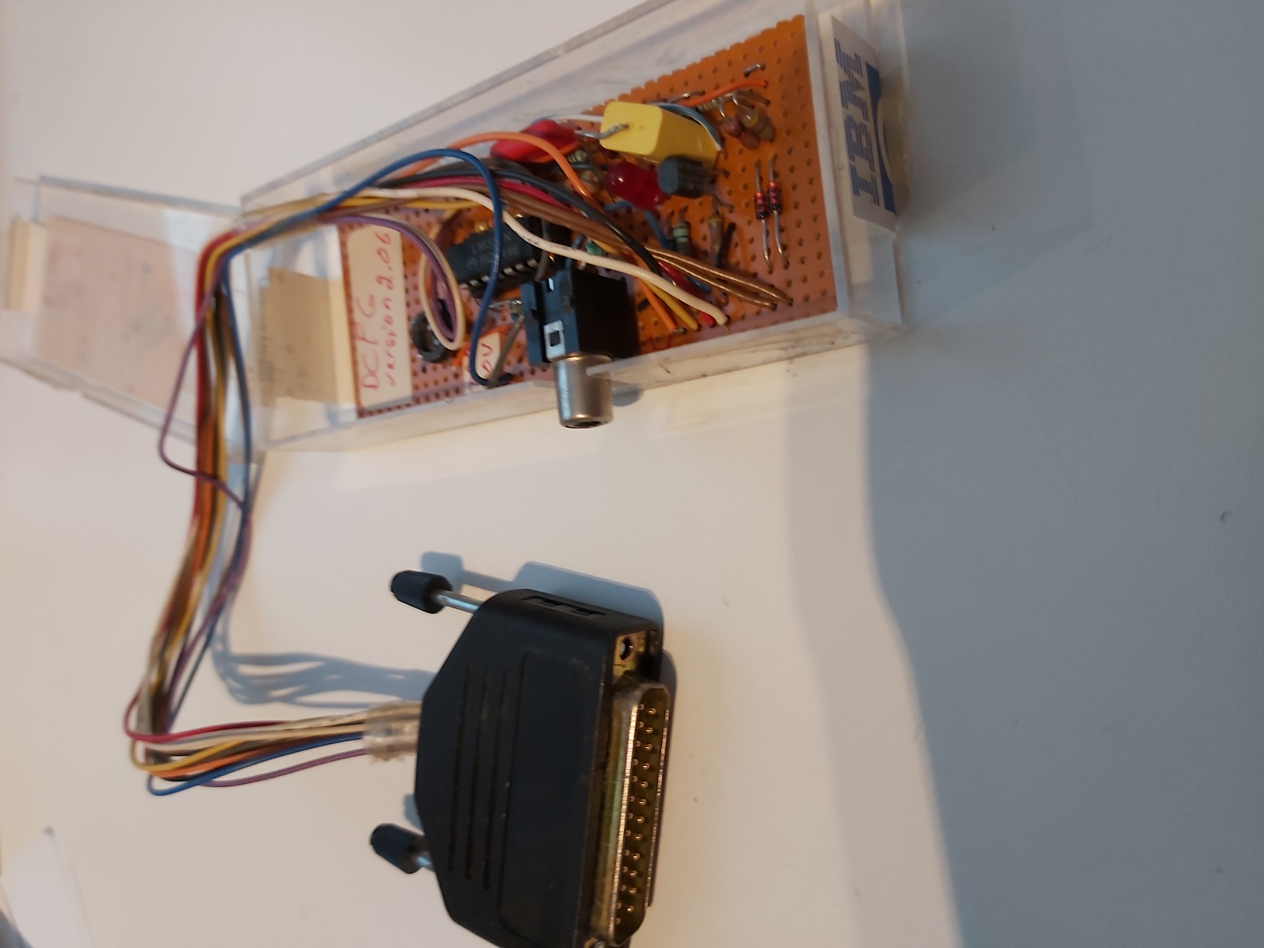
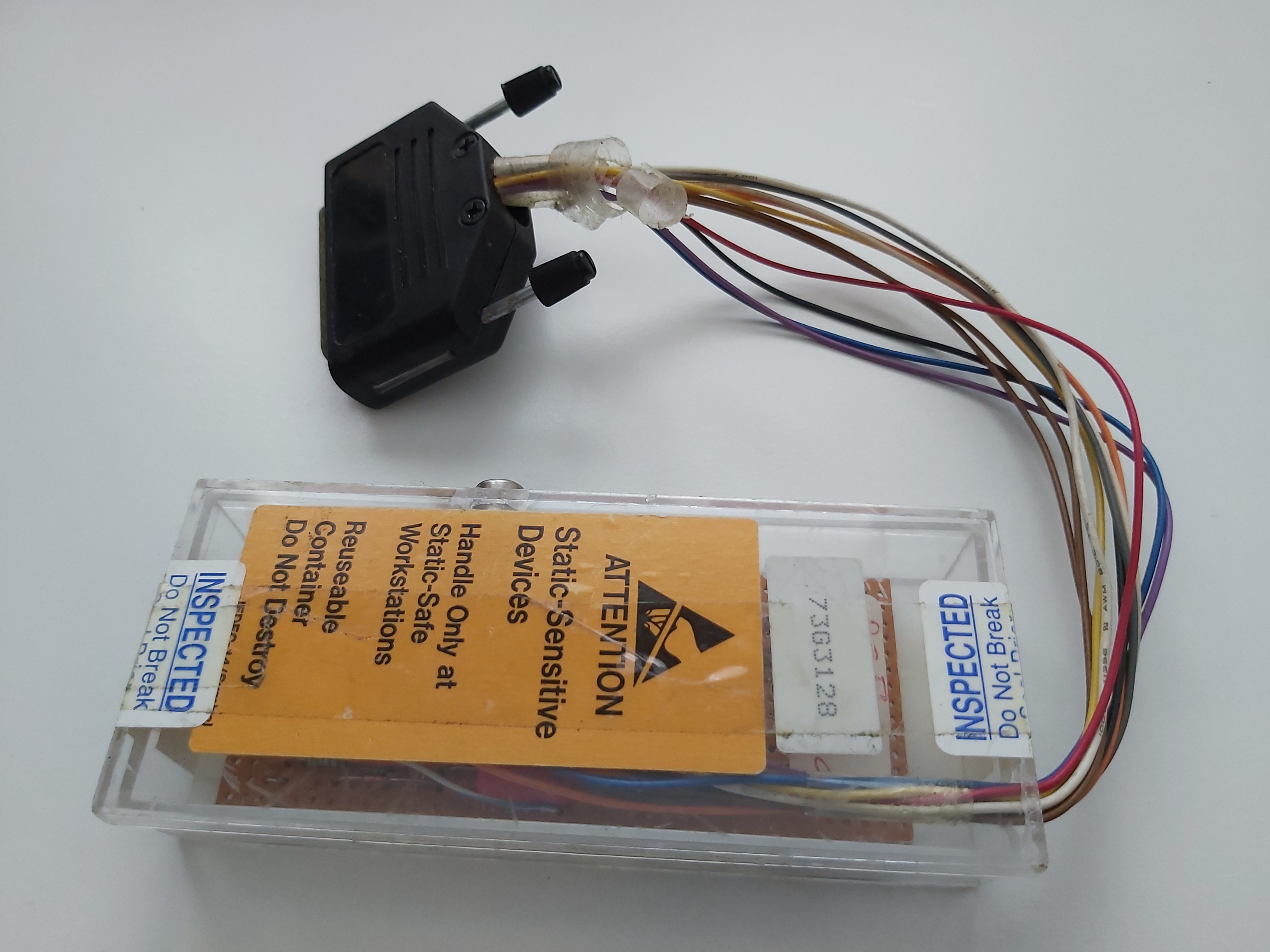
Here is the built circuit in a small plastic box and wire that goes to PC parallel port interface.
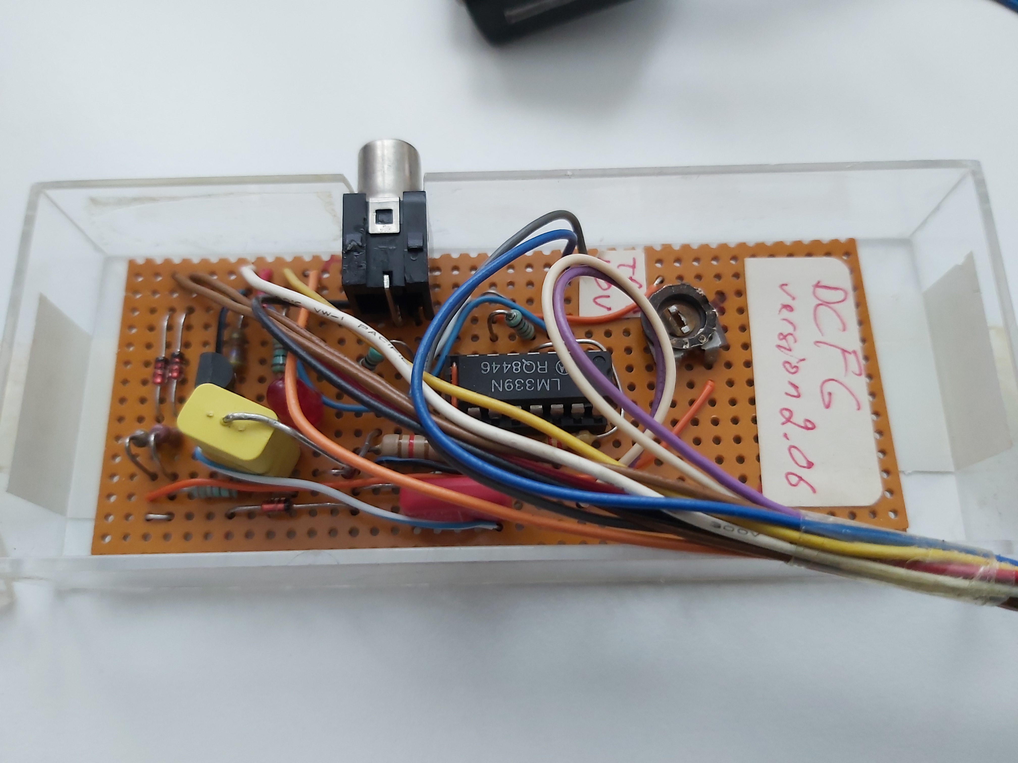
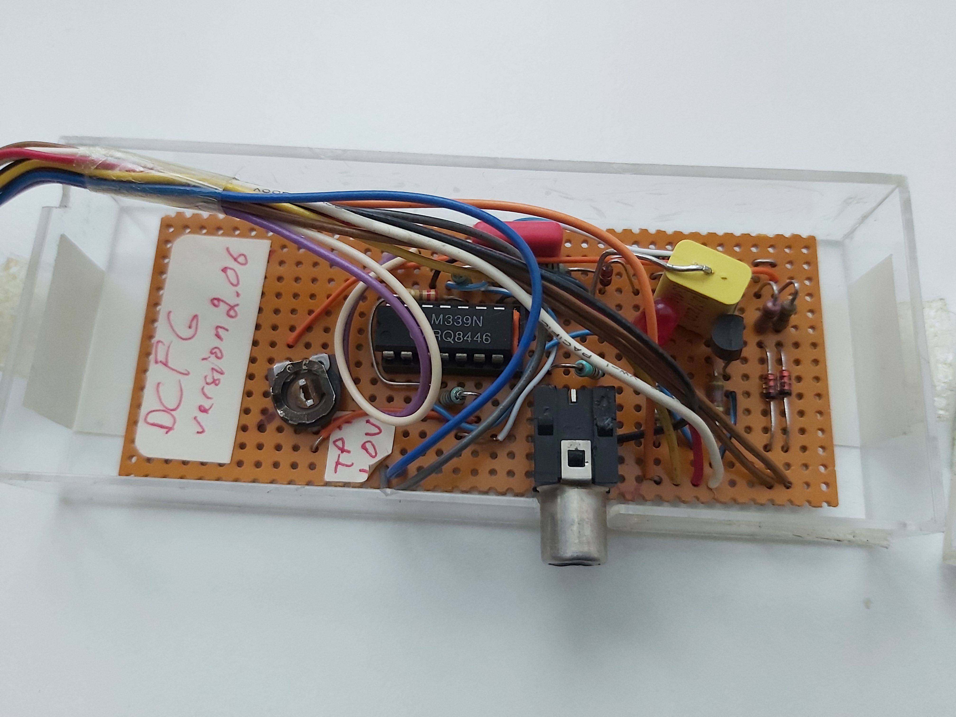
Here is what is inside the box:
And here is the circuit diagram:
                    Dirt Cheap Frame Grabber
    (DB25P)
    DO0 ---330ohm-------------*--->|--*-->|---*    IC1 = LM339
    pin 2                  Vr |  red    1N914 |          quad
                       (2.4v) |  led          |        comparator
    DO1 ---330ohm-------------*               |
    pin 3                     |               |    * = connection
                             330ohm           |
          1N914               |               |    ) = no connect
    DO6 ---|<---*---1Kohm-----* Vc (2.21v)    |       (jump over)
    pin 8                     |               |
          1N914               |               | Vr = ref voltage
    DO7 ---|<---*---510ohm----*------*        |      2.4 volts
    pin 9                     |      |        |
                   (trimmer) 5Kohm<--*        | Vc = 00 = 1.65v
                              |               |      01 = 1.80v
    DO2 ----------*-----------)------| |------*      10 = 1.95v
    pin 4         |           |     .1uf      |      11 = 2.21v
                 3|           |               |
    DC3           |/ |6       |               | Vz = 00 = 0.74v
    (slct)     1 /  -|--------* Vz (1.0v)     |      01 = 0.81v
    DS6 --------|IC1a|        |               |      10 = 0.88v
    (ack)        \  +|----*   |               |      11 = 1.00v
    pins 10,17     \ |7   |  360ohm           |
                          |   |               | Vy = 00 = 0.45v
    DC2            / |4   |   |               |      01 = 0.54v
    (init)     2 /  -|----)---* Vy (0.66v)    |      10 = 0.59v
    DS5 --------|IC1b|    |   |               |      11 = 0.66v
    (pe)         \  +|----*   |               |
    pins 12,16     \ |5   |  220ohm           | Vx = 00 = 0.34v
                          |   |               |      01 = 0.37v
    DC1            / |10  |   |               |      10 = 0.40v
    (afd)     13 /  -|----)---* Vx (0.45v)    |      11 = 0.45v
    DS4 --------|IC1c|    |   |               |
    (slct)       \  +|----*   |               | Vs = 00 = 0.086v
    pins 13,14     \ |11  |  360ohm           |      01 = 0.093v
                          |   |               |      10 = 0.101v
    DC0            / |8   |   |               |      11 = 0.115v
    (stb)     14 /  -|----)---* Vs (0.12v)    |  Assumes Vz set
    DS7 --------|IC1d|    |   |               |  for 1.0v using
    (busy)       \  +|----*   |               |  5Kohm trimmer
    pins 11,1   12|\ |9   |  120ohm           |  with DO6, DO7
                  |       |   |               |  set high.
    Gnd ----------*-------)---*---------------*------*--------*
    pins                  |   |               |      |        |
    18,19,20,21,          |  100Kohm          |     75ohm     |
    22,23,24,25           |   |      .1uf     |      |        |
                          *---*-------| |-----)------*------o )
                   2N2222 |                   |             RCA
            *---------C   E                   |            phono
            |           B                     |            jack
    pin 5   |           |      1N914          |
    DO3 ----*--4.7Kohm--*-------->|-----------*
This circuit consists of four fast comparators. They compare the video signal voltage levels to the the given reference voltage levels. The reference voltage levels are set so, that the circuit can detect four video signal gray scale levels and video sync signal. Those signals are fed to the PC parallel port digital input pins. The circuit takes power from the parallel power data lines (that are set to logic high to provide needed power).
The Dirt Cheap Frame Grabber needs to be connected the computer with a short cable. We are dealing with high speed signals here (up to 4MHz). It requires as short a connection to the computer as you can give it. Here I had around 20 cm long wires.
The DCFG hardware only provides 4 levels of gray scale. From DCFG version 2.01 the software can provide up 12 gray scales by reading the port four times for each display pixel and interpolating the results.
Because video signal is very fast changing signal, it needs to be digitized at fast rate. The heart of the program relies on a very fast IO port to memory instruction. It can operate as fast as the computer can shove data from the port to the memory. This is as fast as DMAing the data could do. The downside is that this method is sensitive to computer speed, and you might need to adjust the horizontal sample size to get viewable picture.
Because of the simple technology and not very accurate sampling, you will probably notice some sparkles (pixels shifting left and right one pixel position). This is caused by sample jitter. The jitter is caused by the fact that the sampler is not perfectly synchronized to the incoming video signal.
To use the Dirt Cheap Frame Grabber, plug it into a PC printer port, and attach the other end to the video output from a VCR or TV Monitor and run the program. Use the left or right arrow keys to adjust the horizontal sample size to obtain a stable picture. Years ago I got this working. I got some small low quality video signal on the computer screen.
This circuit is pretty useless nowadays, when you can buy good quality commercial video digitizing hardware that plugs to USB port for very little money (less than $10 for composite video and HDMI capture for some more money). Other things are that the legacy parallel port are pretty died hardware family, and things like USB-parallel port adapters and different virtualization software approaches will not cut in for this applications.
If you want to explore nowadays to get this hardware to work with some modern PCs for any reason, the best cheap idea could be to connect this hardware to a logic analyzer that can stream the data quickly in real time to PC. For example sigrok software supports lots of hardware, including cheap Chinese clones of some USB logic analyzer hardware. This kind of logic analyzers can record up to 8 channels at up to 24MHz sample rate through USB port to PC. sigrok software can show those signals, and supports you to write your own signal decoder modules that can convert the recorded bit stream to whatever format needed (or example to images). Theoretically I could plug in this DCFG circuit to logic analyzer and then decode video from recorded data. Maybe not worth of the trouble, but should be doable I think.
Here is the original Dirt Cheap Frame Grabber documentation
—
Dirt Cheap Frame Grabber V2.02
by Michael Day
as of 5 January 1992
Public Domain
This device is free and released to the public domain.
If you actually find a use for it, all the more power to ya!
The purpose of the DCFG is to simply provide a very simple method
to grab video pictures and display them on a computer monitor.
Version 1.01 of the DCFG only provided 4 levels of gray scale.
Version 2.01 makes a modification which allows for 12 gray scales
by reading the port four times and interpolating the results.
Version 2.02 fixes a schematic error (DO3 is pin 5, not pin 4).
The DCFG requires at least a 80286 or better and a VGA
display to run. While it is possible to change the program to
allow operation on a 8086 and/or a different display, I’m not
doing it. If you want to, you can. My intent was to just prove
that it was possible.
The frame grabber program at this point is very simple, and as a
result has some problems. The heart of the program relies on a
very fast IO port to memory instruction. It can operate as fast
as the computer can shove data from the port to the memory. This
is as fast as DMAing the data could do. This method is sensitive
to computer speed. As such, you may not get a stable picture at
first. If you don’t, use the left or right arrow keys to adjust
the horizontal sample size. The up/down arrows adjust the
vertical sample size, but this normally doesn’t need to be done.
You will probably notice some sparkles (pixels shifting left and
right one pixel position). This is caused by sample jitter and is
normal. All sampling systems have this problem. Some less than
others. Even your TV has the problem, but it is normally good
enough that you don’t see it.
The jitter is caused by the fact that the sampler is not
perfectly synchronized to the incoming video signal. Your TV has
a lot of circuitry in it to achieve the synchronization. Being
that this is a dirt cheap frame grabber, there is only limited
synchronization of the picture, and no synchronization of the
sampler. If you want to try to improve on it, please do.
To use the Dirt Cheap Frame Grabber, plug it into a PC printer
port, and attach the other end to the video output from a VCR or
TV Monitor and run the program. Use the left or right arrow keys
to adjust the horizontal sample size to obtain a stable picture.
Do not attach the Dirt Cheap Frame Grabber to the computer with a
long printer cable. We are dealing with high speed signals here
(up to 4MHz). It requires as short a connection to the computer
as you can give it. I built my circuit inside the back shell of
the connector that plugs into the printer port on the computer.
                    Dirt Cheap Frame Grabber
    (DB25P)
    DO0 ---330ohm-------------*--->|--*-->|---*    IC1 = LM339
    pin 2                  Vr |  red    1N914 |          quad
                       (2.4v) |  led          |        comparator
    DO1 ---330ohm-------------*               |
    pin 3                     |               |    * = connection
                             330ohm           |
          1N914               |               |    ) = no connect
    DO6 ---|<---*---1Kohm-----* Vc (2.21v)    |       (jump over)
    pin 8                     |               |
          1N914               |               | Vr = ref voltage
    DO7 ---|<---*---510ohm----*------*        |      2.4 volts
    pin 9                     |      |        |
                   (trimmer) 5Kohm<--*        | Vc = 00 = 1.65v
                              |               |      01 = 1.80v
    DO2 ----------*-----------)------| |------*      10 = 1.95v
    pin 4         |           |     .1uf      |      11 = 2.21v
                 3|           |               |
    DC3           |/ |6       |               | Vz = 00 = 0.74v
    (slct)     1 /  -|--------* Vz (1.0v)     |      01 = 0.81v
    DS6 --------|IC1a|        |               |      10 = 0.88v
    (ack)        \  +|----*   |               |      11 = 1.00v
    pins 10,17     \ |7   |  360ohm           |
                          |   |               | Vy = 00 = 0.45v
    DC2            / |4   |   |               |      01 = 0.54v
    (init)     2 /  -|----)---* Vy (0.66v)    |      10 = 0.59v
    DS5 --------|IC1b|    |   |               |      11 = 0.66v
    (pe)         \  +|----*   |               |
    pins 12,16     \ |5   |  220ohm           | Vx = 00 = 0.34v
                          |   |               |      01 = 0.37v
    DC1            / |10  |   |               |      10 = 0.40v
    (afd)     13 /  -|----)---* Vx (0.45v)    |      11 = 0.45v
    DS4 --------|IC1c|    |   |               |
    (slct)       \  +|----*   |               | Vs = 00 = 0.086v
    pins 13,14     \ |11  |  360ohm           |      01 = 0.093v
                          |   |               |      10 = 0.101v
    DC0            / |8   |   |               |      11 = 0.115v
    (stb)     14 /  -|----)---* Vs (0.12v)    |  Assumes Vz set
    DS7 --------|IC1d|    |   |               |  for 1.0v using
    (busy)       \  +|----*   |               |  5Kohm trimmer
    pins 11,1   12|\ |9   |  120ohm           |  with DO6, DO7
                  |       |   |               |  set high.
    Gnd ----------*-------)---*---------------*------*--------*
    pins                  |   |               |      |        |
    18,19,20,21,          |  100Kohm          |     75ohm     |
    22,23,24,25           |   |      .1uf     |      |        |
                          *---*-------| |-----)------*------o )
                   2N2222 |                   |             RCA
            *---------C   E                   |            phono
            |           B                     |            jack
    pin 5   |           |      1N914          |
    DO3 ----*--4.7Kohm--*-------->|-----------*
Parts List
1ea DB25P connector
1ea RCA phono jack
1ea 5K ohm trimmer pot
1ea 510 ohm resistor
1ea 1K ohm resistor
2ea 330 ohm resistor
2ea 220 ohm resistor
2ea 360 ohm resistor
1ea 120 ohm resistor
1ea 100K ohm resistor
1ea 75 ohm resistor
1ea 4.7K ohm resistor
2ea 0.1uF capacitor
1ea red LED
4ea 1N914 diode (or 1N4148)
1ea 2N2222 transistor (NPN)
1ea LM339 quad comparator
-----------------------------------------------------------------
Dirt Cheap Frame Grabber
Circuit Description
It is assumed that the video signal will be a NTSC type signal
complying to the RS170A video standard with negative going sync
and a signal level between 0.5Vpp to 2Vpp (1Vpp desired). This is
the typical signal that is available on the video output jack of
a VCR or TV monitor.
If you are using a VCR type video signal, you can get a quick
start by adjusting the bias trimmer (5Kohm pot) to obtain
1.0volt at location Vz while insuring that the data output lines
on the printer port are set to 0FFH. Once you get going you can
fine tune the reference voltage by adjusting the trimmer to
obtain the best picture.
The video input comes in on the RCA phono jack. The 75ohm
resistor provides the proper load for the connection. The .1mf
capacitor isolates the signal from the rest of the circuit and is
used as a part of the level shifter to clamp the video input to
ground reference on the computer. The 1N914 diode and 4.7K ohm
resistor provides a voltage reference 0.7V above ground for the
2N2222 clamp transistor. The transistor and diode get their
supply voltage from the DO3 output pin. Typically this is around
3.3volts and should have enough power for our needs assuming that
the output driver is a 74LS374 driver which is the standard part
for a PC printer port.
capacitor to clamp the sync tip to ground so as to insure the
video signal sync tip is referenced to ground. The 100K ohm
resistor provides a high resistance discharge path for the
capacitor. Enough to provide a discharge path for the capacitor,
but not enough to seriously affect the video signal level.
The clamped video signal is then applied to all four comparators
in the LM339. The LM339 gets its power from the DO2 output pin
Like the clamp transistor, normally there should be enough power
from the data output pin to supply the IC. A .1mf capacitor is
used to stabilize the power source. You can probably getaway
without using the capacitor, but I'm paranoid.
The four comparators receive their reference voltage from a
resistor ladder consisting of 360ohm, 220ohm, and 360ohm
resistors in series with the 120ohm resistor tied to the common
ground. The voltage level on the 120ohm resistor provides the
sync detector reference. The other three resistor positions
provide three increasing levels of amplitude detection.
The resistor ladder voltages can be shifted up or down by the
computer using the DO6 and DO7 data output lines on the printer
port. This allows 12 gray scale levels to be detected instead of
the basic 4 levels that would otherwise be available.
The resistor ladder requires a regulated source voltage with an
adjustment to allow compensation for various input signal levels
depending on the signal source. The 5Kohm trimmer pot provides
for the bias adjustment which allows the circuit to be adapted to
the absolute signal source level. The regulated source voltage is
derived from the red LED in series with a 1N914 diode. A red LED
will have a typical voltage drop of about 1.7 volts and the diode
has a typical voltage drop of 0.7 volts giving a total of 2.4
volts for the reference.
The absolute level is not important since the trimmer can
compensate for minor differences. The LED gets its power through
the two 330ohm resistors attached to the D0 and D1 outputs. Two
outputs are used here to insure that there is enough power to
drive the LED and the resistor ladder while maintaining a
regulated voltage source across the LED.
The LED has a 1N914 diode in series with it to get the reference
voltage in the range that we need it. This is the one area where
I go beyond spec for the system. The 74LS374 driver is specified
to have an output voltage of greater than 2.5volts at 2.5ma. I'm
actually relying on the true output voltage for the part which is
typically 3.3volts. Should your printer port use a different part
than the 74LS374, the circuit may or may not work properly. A
74HTC374 cmos type part will pull up to 5volts. This is not a
problem, since all we need is 3 volts or better source voltage to
supply the circuit. If the output device supplies less voltage,
the circuit will not work because the LED and diode will not be
able to maintain the required 2.4volt reference source.
The voltage reference is supplied through a 220ohm resistor to
the bias adjustment trimmer pot. The 220ohm resistor is a load
source for the 1Kohm and 510ohm gray level shift control
resistors attached to the DO6 and DO7 data output pins. The gray
level shift control lines change the reference voltage on the
resistor ladder to allow the computer to adjust the reference
voltage to four different levels. This allows us to multiply the
gray level detection by four by reading in four sequential video
frames at the four possible reference control levels and
selecting the highest determined video level from the four frames
that are collected. This gives us a total of 12 gray levels
instead of the four levels that would otherwise be available.
The down side to this is that we have to collect four separate
video frames to do this which means that motion will be blurred.
The comparators receive their pull-ups from the control lines DC0,
DC1, DC2, and DC3. In a standard printer port these lines are
open collector outputs with 4.7Kohm pull up resistors. It is
presumed that this is the case for this circuit. It saves us the
four pull up resistors. If you feel nervous about this, you can
attach 4.7Kohm pull up resistors to the comparator outputs and
attach two each to the remaining DO4 and DO5 output pins (pins 6
and 7). Note that you should not draw more than 2.5ma from any
data output pin or the output voltage may sag.
When wiring the circuit, remember that you are working with video
signals. That means you are working with signals in the RF range
(up to 4MHz). Keep all wiring as short as possible and the
components close together. All grounds should be tied to one
single point at the 25pin connector. The circuit must be built as
close as possible to the DB25P connector as possible. Do not
attach this device to the computer with a long cable. The DB25P
connector must plug directly into the computer to prevent signal
loss. Any attaching cable should be no more than six inches
long. If possible, I suggest building the circuit into the back
shell of the connector so that there is no cable involved.
Remember that we are dealing with high speed signals here.
Long cables don't work. Failure to keep the connection short will
cause the sync signal not to be detected and the picture to blur
or smear. The video cable attached to the RCA jack can be any
length (within reason) since it is not as sensitive to cable
length problems. Video cable lengths longer than 20 feet
may cause problems, I haven't tried them that long.
If you are good at this stuff, it is possible to wire the whole
circuit inside the connector shell (don't use a shielded shell,
it will short out the circuitry). It's a very tight fit, but if
you pick a large shell, and are very careful, it can be all
stuffed in there. The trimmer pot should be made available for
easy adjustment (I drilled a hole in the shell for access).
Also, the led should be visible (another hole to drill) to be
able to quickly determine if the circuit is working.
port on the PC, and run the frame grabber program. When running
the program, the LED should turn on. That indicates that the
circuit has enough power to operate. If the LED does not come on,
or it is very dim, there may not be enough power, and you can't
use that printer port with the circuit. Try another port or a
different computer. Note that you may see some minor flickering
on the led when changing the DO6 and DO7 data output lines. This
is normal and indicates that the circuit is working properly.
Changing the DO6 and DO7 data output lines causes the current
flow through the voltage reference ladder to change. This means
that more or less current will be available to the LED, causing
it to change in brightness. The LED should not go out completely
nor become very dim. That would indicate that there is not enough
power available to drive the voltage reference or a problem in
your program.
You can operate in the simple mode by outputting a 0FFH to the
data output port which sets all the output lines high. This
provides power to the comparators, voltage reference, and clamp
transistor. It also disables the gray scale control lines.
To shift the gray scale reference voltage level, send either a
03FH (gray ref 0), 07FH (gray ref 1), 0BFH (gray ref 2), or 0FFH
(gray ref 3) to the data output port.
The resulting detected output from the port is as follows:
76543210
1000xxxx sync
0000xxxx level 0 (black)
0001xxxx level 1 (dark gray)
0011xxxx level 2 (gray)
0111xxxx level 3 (white)
Note that bits 0-3 are unknown and should not be relied on as
being valid.
-----------------------------------------------------------------
Program Description
Thió prograí requireó á 28¶ oò betteò computer® Á printeò porô �
witè thå attacheä devicå describeä abovå witè á videï signaì �
drivinç it® Anä á MCGÁ oò VGÁ typå displaù system® Yoõ starô thå �
prograí uð bù enterinç itó namå aô thå DOÓ prompô followeä bù thå �
printeò porô numbeò yoõ wisè tï use®
Examplesº DCFG² 1 <- loadó prograí foò uså witè LPT1.
DCFG² 2 <- loadó prograí foò uså witè LPT2.
Iæ yoõ don'ô givå iô á number¬ thå prograí wilì defaulô tï LPT1®
Grabbing a Frame:
The program works by grabbing samples from the printer port in
frames. Once each time through the loop, it sucks in a video
frame from the video input.
Actually, more than a frame is grabbed. How much is grabbed
depends on the speed of access to the printer port on your
computer. On a typical computer this is 1.5us per byte. At the
1.5us access rate, 63.5us per scan line, and 265.5 scan lines per
video frame, that results in 11240 bytes per frame required to be
collected. The collection size is currently set to 20,000 bytes.
That provides enough space to handle buss speeds up to 12MHz which
should be adequate for most computers.
The down side is that we collect 210 extra scan lines on a normal
computer. In most situations this isn't a problem since three to
four frames will typically be lost while the collected video data
is being processed anyway. The extra partial frame has only a
slight effect on the over all collection time and results. The
effect is minimized on a fast machine since nearly the entire
array is filled anyway.
The maximum sample size allowed is 65520. More than that and we
run out of segment space in memory. Also during this period I
keep the system interrupts off so as to not have distortions of
the collected data caused by the system deciding to go off and do
something else.
In addition to the collection time, there is a pre-configure time
while the loop is waiting for the vertical sync pulse to come in.
I don't collect any data prior to the vertical sync pulse since
it would be ignored anyway.
The vertical sync is determined by watching the sync line. When
it goes on for longer than 10us, you are in the vertical sync
time. Less then 10us, and it is a horizontal sync pulse.
Once the video data is collected, I release the interrupts to
allow the computer to return to normal operation. Should no sync
come in during the vertical sync detection period, I terminate
the loop after a while to allow the computer to continue to
operate, and return an error condition so that the program will
know that no data was collected.
If you have an O'scope, you can verify the video collection time
by observing data output line DO7 (pin 9). This line should never
go high for longer than 50ms. Typically it should be around 20 to
40ms in length. This should be the same whether you have a signal
going into the video line or not. Though there may be a
difference between the timing when a signal is present verses
when it is not present.
Once I get the data, I convert it to in intermediate form to be
stored in the interpretation array. This array keeps the gray
level values collected on the previous frames. The display
routine will later interpret the values stored in the
interpretation array into an absolute gray scale level for each
display pixel.
The video data is converted by searching for the horizontal sync
pulse. Once found, we search for the end of the sync pulse.
Following the end of the sync pulse is the actual video data.
Each collected byte in the scan line is read and converted to the
intermediate gray scale level. There are only four levels
involved; 00, 01, 10, and 11. Note that since sync is not video
data, it is not included in the gray scale level. Even if it were
included, it would be a 00 value. Once converted, the byte is
then shifted into it's proper frame position in the interp array
byte and stored in the array.
This is repeated until either the full width of the
interpretation array is filled, or a new sync pulse is
encountered. Should a sync pulse be encountered, the rest of the
interpretation array values are filled with 00. Should the full
width of the interpretation array be encountered, then the rest
of the scan line is discarded until an new sync pulse is
encountered. This sequence is continued until the entire frame
has been converted.
Displaying the Data:
Once the frame has been converted, the interpretation array is
then displayed. Each byte is read from the interpretation array
and translated to an absolute gray level using the translation
array located in the first 256 bytes of the interpretation array.
There are 12 levels of gray available, plus black. The
translation array was copied into the interpretation array at the
time the interpretation array was created.
conversion chart:
gray level interpretation chart
frame data
gray F3 F2 F1 F0 F3 = frame 3, F2 = frame 2
level: 76 54 32 10 F1 = frame 1, F0 = frame 0
12: 11 xx xx xx each group of two bits
11: <11 11 xx xx represent the video level
10: <11 <11 11 xx for the frame indicated
9: <11 <11 <11 11
8: 10 <11 <11 <11 xx = any bit pattern
7: <10 10 <11 <11 <11 = less than 11; (10, 01, 00)
6: <10 <10 10 <11 <10 = less than 10; (01 or 00)
5: <10 <10 <10 10 11, 10, 01, or 00 = the indicated
4: 01 <10 <10 <10 absolute bit pattern
3: 00 01 <10 <10
2: 00 00 01 <10 the gray level for the specified
1: 00 00 00 01 bit pattern is shown at the left
0: 00 00 00 00
There are no sync bytes in the interpretation array since they
were stripped out during the process of converting the video data
to the interpretation data. Note that it takes four video frames
to completely update the interpretation array. However, the
actual displayed data will reflect the highest gray level
determined from the four previous reads. This means that if the
video level shifts towards the white level, the change on the
display will be immediate. If the video level moves towards the
black level, the change on the display will take up to four frame
grabs to reflect the lower video level for that pixel.
One big problem is that since the number of scan lines collected
is much greater than the resolution of pixels collected in each
scan line, the aspect ratio of the picture would be out of whack
if we were to display the data pixel for pixel as we received it.
In order to get the aspect ratio back to a reasonable value, we
must throw data away. We do this by discarding three scan lines
for every one that we show. If you have a very fast buss, you may
want to change this to discard two scan lines instead of three
in order to get a more reasonable aspect ratio.
The other thing I do is to pull a little trick to improve the
horizontal resolution. Normally there is a typical horizontal
resolution of about 40 pixels. This is not very much, and it
would be useful if there were a better resolution. There is a
halfway solution.
What I do is display the even pixels on a scan line from the scan
line that I'm currently processing. I then display the odd pixels
from the next scan line on the succeeding video frame. What this
does is to provide a random selection on the odd pixels between
the normal two sequential scanned pixels that effectively
improves the display resolution by about 50%.
hat it worsens the jitter/twinkle problem since
the odd pixel is developed from a pseudo-random sampling
mechanism which is not consistent.
One thing to keep in mind is that the frame grab routine normally
takes between one and three video frames to collect data, and
during this time the interrupts are disabled. What that means is
that if you are operating on a computer which has a clock
interrupt faster than the normal 55ms, you will lose time, and
may experience problems.
Also note that since the interrupts are disabled, anything that
uses high speed interrupts during the time the video data is
being collected (such as RS232), will not work. The interrupts
will be lost.
The main factor that affects speed on slower machines are the
conversion and display routines. The INS instruction used to
collect the video data is relatively cpu performance independent.
The main thing that affects its operation is the buss performance
of the computer. The faster the buss, the more video pixels that
can be collected per scan line.
One possible consideration on slower machines would be to discard
the extra scan lines in the Video to interpretation array
conversion rather than in the interpretation to display routine.
That way the extra scan lines would not even be processed, thus
increasing the speed of the overall process loop.
---
Future considerations for someone to do if they wish to improve
on the design would be to improve the synchronization to reduce
the jitter problem. At this point I don't have any ideas on how
to improve the problem.
Another improvement that is possible to do would be to analyze the
captured video frame to determine the proper values to use for
capturing the data such as scan line length in pixels, vertical
sync length, total scan lines, etc.
A mechanism to increase the size of the displayed picture, and
maintain the best resolution possible while doing so.
Save an image to disk or a series of images to make a movie.
Be able to print a captured image.
Integrate the image with sound.
And of course integrating this stuff into Windows would be nice.
That's all folks!
###########################################################################
2 Comments
Tomi Engdahl says:
How old school video digitizers worked
https://www.youtube.com/watch?v=4vpKsteIzJs
In this episode I take a look at how oldschool video digitizers like the “computer eyes” for the Commodore 64.
Tomi Engdahl says:
There was software that was running on the PC end. It sampled data from parallel port and then displayed it on screen. Capture approximately two frames time. Then process it by finding start sync pulse. Display frame. Clean receive buffer. Sample again and decode again.
The X resolution was quite low, due the limited rate PC could sample data from parallel port.
In Y direction the image was scaled so that several scan lines were summed together to form one output line. The summing allowed to increase effective number of pixel gray scale values it can get (so it look there is better Grey scale resolution than what the AD hardware can give).